
Summary of Contents for HMA 1200
- Page 1 Revision 2016-1-1 Copyright ©, 2016 by HMA Group. The information contained in this document is subject to change without prior notice.
-
Page 2: Table Of Contents
Field Installation Records Sheet ........................14 Standard Temperature vs Resistance Values ..................... 15 Definitions ................................. 16 HMA Group Conditions of Supply ....................... 17 Important Note Always ensure that the zero reading is taken at installation. For further information, see the data reduction and installation sections of this manual. -
Page 3: Introduction
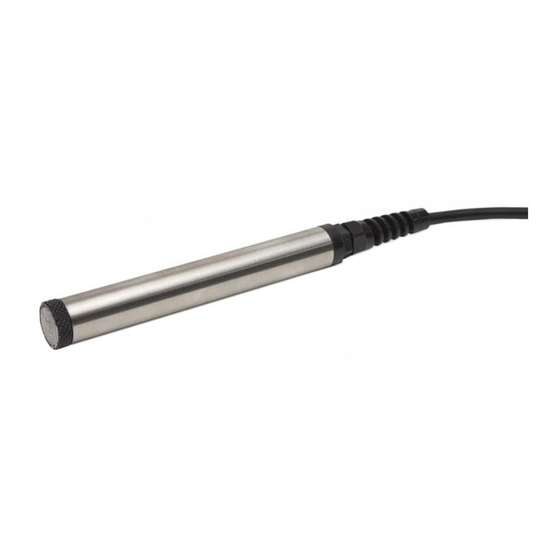
1. Introduction: The HMA Geotechnical Vibrating Wire Piezometer has been designed to easily measure remote fluid pressures in earthen masses. The Vibrating Wire Piezometer functions on the principle of tensile wire vibration. As the native reading taken is a frequency measurement, water penetration, temperature variations and contact resistance do not affect the output unlike several other types of electrical instrumentation. -
Page 4: Specifications
2. Specifications: Piezometer Pressure Ranges (kPa) 350, 700,1000 2000, 3000, 5000 Over Range 1.5 x Rated Pressure Resolution 0.025% full scale Accuracy < 0.5% full scale Operating Temperature -20 to 60⁰C Filters 0.5 and 20 micron Dimensions 19mm dia, 136mm long Weight 0.11kg Signal Output... -
Page 5: Vibrating Wire Piezometer Operation
3. Vibrating Wire Piezometer Operation The HMA Geotechnical Vibrating Wire Piezometer provides a reliable static pressure output to be utilised in a number of applications, such as: • Water level monitoring • Soil deposit pressure monitoring • Compacted fills for dams •... -
Page 6: Calibration And Interpreting Readings
Both testers are traceable to the national standards at the National Bureau of Standards (U.S.A). Each Vibrating Wire Piezometer ships with a calibration sheet provided by HMA Geotechnical. 4.1 Electrical Connection Figure 2. Typical HMA Geotechnical Vibrating Wire Piezometer cable... -
Page 7: Calibration Sheet Interpretation
4.2 Calibration Sheet Interpretation HMA Geotechnical supplied piezometers include basic information such as the client name, job number, serial number, and pressure rating at the top of the page. These are important records to keep, please ensure these sheets are filed away safely. -
Page 8: Data Reduction
4.3 Data Reduction To calculate the pore water pressure being applied to the piezometer the following formula should be used: P = (F – F + (T – T Where Pressure (Dependant on pressure coefficient, usually kPa) Zero reading prior to installation taken at site (Hz x 10 Current piezometer reading (Hz x 10... -
Page 9: Pressure Head/Water Level Calculation
The vent tube is terminated with a desiccant chamber to prevent moisture ingress. HMA Geotechnical can supply these piezometers when requested. Page 9 of 19... -
Page 10: Installation Procedure
5.2 Installation in Boreholes (traditional sand layer method) HMA Geotechnical piezometers can be installed in boreholes in either cased or uncased holes. Careful attention must be paid to borehole sealing techniques if pore pressures in a particular zone are to be monitored. -
Page 11: Installation In Boreholes (Direct Grout Method)
5.3 Installation in Boreholes (direct grout method) HMA Geotechnical piezometers can be installed in boreholes in either cased or uncased holes. Careful attention must be paid to borehole sealing techniques if pore pressures in a particular zone are to be monitored. -
Page 12: Installation In Fills And Embankments
5.4 Installation in Fills and Embankments HMA Geotechnical piezometers are normally supplied with direct burial cable suitable for placement in fills such as highway embankments and dams, both in the core and in the surrounding materials, each installation must be treated separately. -
Page 13: Instrument Troubleshooting
6. Instrument Troubleshooting To ensure that the vibrating wire piezometers are functioning properly it is advised that the instrument be checked periodically. As the transducers are sealed they cannot be opened for inspection, hence for inaccurate readings the flow chart below should be employed. Figure 4. -
Page 14: Field Installation Records Sheet
7. Field Installation Records Sheet To assist with installations in the field, HMA Geotechnical provide a standard installation record sheet that allows any field operator to quickly record key data to be used by monitoring engineers at a later date. -
Page 15: Standard Temperature Vs Resistance Values
8. Standard Temperature vs Resistance Values Temp Temp Temp Temp Ohms Ohms Ohms Ohms 53100 4105 13390 1475 49910 3922 12700 1418 46940 3748 12050 1363 44160 3583 11440 1310 41560 3426 10860 1260 39130 3277 10310 1212 36860 3135 9796 1167 34730... -
Page 16: Definitions
9. Definitions Factory Reading The reading taken at the factory during calibration and shown on the calibration sheet. Site Test Reading The reading taken on receipt of the equipment to prove its functionality after shipping. Zero Reading The reading taken during the installation and used for all subsequent calculations. This is the most important reading the installer must take during a field install. -
Page 17: Hma Group Conditions Of Supply
HMA Group Conditions of Supply Accurate as of 14 July 2015. Subject to change. An up to date copy can be viewed at hmagrp.com. Page 17 of 19... - Page 18 Page 18 of 19...
- Page 19 Page 19 of 19...
Need help?
Do you have a question about the 1200 and is the answer not in the manual?
Questions and answers