Table of Contents
Advertisement
Quick Links
4
Specifications
LED Indications
Start-up Mode:
Flashing Red
-
Pulse Relay, waiting for first 'Master' Card
Flashing Orange and Green
-
Latch Relay, waiting for first 'Master' Card
Programming Mode:
Solid Orange
-
Programming mode, waiting to add/remove users
Green
-
User added
Red
-
User removed
Standard Operating Mode (3 Second Pulse)
Red
-
Normal operation, waiting for card/tag
Green + buzzer
-
Valid card/tag presented
Red + buzzer
-
Invalid user
Standard Operating Mode (Latch)
Valid user
-
LED alternates between Green and Red and
buzzer will sound
Invalid user
-
LED remains Green or Red and buzzer sounds
Technical Specifications
Input Power Supply
Average Current Consumption
Relay Rating
Operating Frequency
Indications
Visual
-
Tri-Colour LED
Audible -
Buzzer
Mechanical
Packaging Formats:
ABS blend, UV resistant
Stainless Steel / Vandal resistant
Industry Standard Panel Mount (40mm x 40mm)
Operating Temperature
-10°C to +60°C
Protection Category
IP67 (Submersible)
Note: The Relay has a rating of 5A @250V AC maximum.
If switching a load with a higher current rating, use an external relay with the neces-
sary current rating. ALWAYS fit a MOV across the coil of this interface relay.
Controlsoft UK
+44 (0)1451 844896
support@controlsoft.com
controlsoft.uk.support
Information on all our products can be found on our website www.controlsoft.com
12V DC
30mA
5A @ 250V AC
125 KHz
Read Range
ISO Card
-
70mm
Tags
-
50mm
Installation Instructions
Introduction
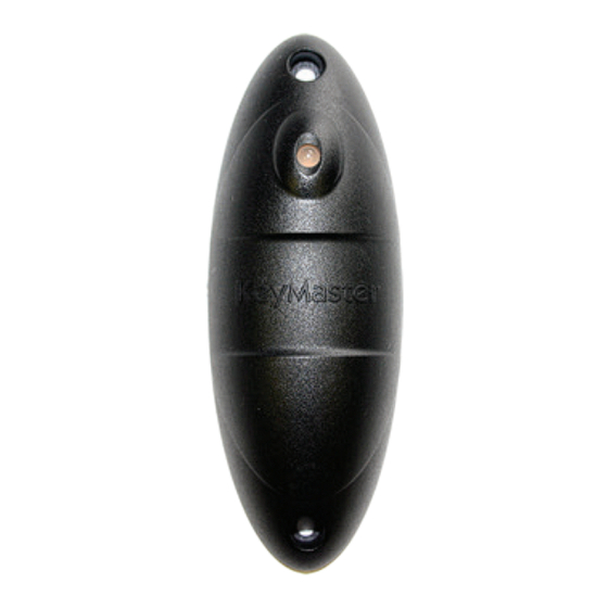
The AC-3100, AC-3101 and AC-3102 from Controlsoft® are standalone "All-in-One"
controllers with integral reader, supporting up to 30 users. The 3 versions operate
exactly the same way, the only difference being how they are housed.
The 3 colour LED indicates the door status making the All-in-One very easy to use.
AC-3100
AC-3101
Mullion
Resistant
Important notes before you continue
• The All-in-One operates on 12V DC only.
• If the latch option is selected and the reader is connected to an electric strike lock,
the coil of the strike lock is likely to burn out.
• Before adding cards/tags to the All-in-One it must be in the chosen relay operating
mode. (Latch or Pulse)
Step 1 — Mounting the All-in-One
• AC-3100: Use the Mounting Template provided to mark the 3 required holes.
• AC-3101: Remove the 4 security screws and separate the cover from the base. Use the
base as a template to mark the required holes.
Drill and plug the wall.
Push the cable from the All-in-One through the centre hole and secure the All-in-One to
the wall.
9010-0004 Iss 2
All in One
Part Codes: CS-AC-3100
CS-AC-3101
CS-AC-3102
AC-3102
Vandal
Panel
Mount
www.controlsoft.com
Advertisement
Table of Contents

Subscribe to Our Youtube Channel
Summary of Contents for Controlsoft AC-3100
- Page 1 Protection Category IP67 (Submersible) • AC-3100: Use the Mounting Template provided to mark the 3 required holes. Note: The Relay has a rating of 5A @250V AC maximum. • AC-3101: Remove the 4 security screws and separate the cover from the base. Use the If switching a load with a higher current rating, use an external relay with the neces- base as a template to mark the required holes.
- Page 2 3 seconds (PULSE mode) or indefinitely (LATCHED mode). For Strike Locks, use normally open breakglass contacts (B & C on Controlsoft breakglass) NOTE: To lock the door in LATCHED mode, simply present the ’MASTER’ card again For Mag Locks, use normally closed breakglass contacts (A &...
Need help?
Do you have a question about the AC-3100 and is the answer not in the manual?
Questions and answers