
Summary of Contents for Lippmann Geophysikalische Messgeräte 4point light
- Page 1 Lippmann Geophysikalische Messgeräte 4point light Earth resistivity meter Operating instructions Software Version 4.58 Mapping Remote Tomography Monitoring...
- Page 2 Contact Erich Lippmann - Geophysical Instruments Kornacker 4 ▪ D-94571 Schaufling ▪ Germany Phone +49 (0)9904 – 84 076 ▪ Skype erich.lippmann www.l-gm.de ▪ lippmann@l-gm.de Copyright © Erich Lippmann – Geophysical Instruments, Schaufling 2014 Reprint in whole or in part only allowed with the written approval of Erich Lippmann.
-
Page 3: Table Of Contents
Constant output current ................16 Variable transmitter frequencies ...............16 Specific noise suppression ...............17 Induced polarization ...................18 Description of the instrument ..............19 Commissioning ..................20 Power supply ....................20 Automatic charging ..................21 Operating modes ..................21 Operating instructions 4point light 10W (V 4.58) Page 3 of 130... - Page 4 8.4.2 Sending commands to the electrodes ............. 60 8.4.3 Possible error messages ................. 61 Tomography mode ..................63 8.5.1 Load ......................64 8.5.2 Show ......................65 8.5.3 Delete ....................... 66 Page 4 of 130 Operating instructions 4point light 10W (V 4.58)
- Page 5 8.10.5 Save ......................97 8.10.6 Load ......................97 8.11 Misc ......................98 8.11.1 Provider ....................99 8.11.2 Calibration ....................100 Troubleshooting .................. 108 General error messages ................108 Error messages in remote mode .............108 Operating instructions 4point light 10W (V 4.58) Page 5 of 130...
- Page 6 10.2.5 Monitoring ....................116 Monitoring GPRS – error numbers ............121 10.3 10.4 Installing new software ................124 10.5 Working with HTerm .................125 11 Technical data ..................127 12 Index ....................129 Page 6 of 130 Operating instructions 4point light 10W (V 4.58)
-
Page 7: Important Information
The following guidance notes allow fast access to the requested information: ▪ Contents ▪ Register ▪ Index The register directly leads from the front page to the individual measurement modes. Operating instructions 4point light 10W (V 4.58) Page 7 of 130... -
Page 8: Instructions
CAUTION Warning which refer to risks of personal injury that may lead to minor or moderate injury ! NOTICE Warning of potential material damage Warning of data loss Page 8 of 130 Operating instructions 4point light 10W (V 4.58) -
Page 9: Safety
Safety 2 Safety The earth resistivity meter 4point light 10W is allowed to be put into operation only if the following operating instructions are read carefully and if the safety instructions are observed. → This instrument may be operated by suitably qualified personnel only. - Page 10 → Set the instrument out of operation → Mark the instrument as defective → Send the instrument back to the manufacturer for maintenance and repair Page 10 of 130 Operating instructions 4point light 10W (V 4.58)
- Page 11 → Before starting the measurement wait several minutes until the instrument reached the ambient temperature → Do not perform measurements under condensing conditions (fog) Operating instructions 4point light 10W (V 4.58) Page 11 of 130...
-
Page 12: Intended Use
2.2 Intended use The earth resistivity meter 4point light 10W is a high precision instrument for determination of soil resistivity. The electrical resistivity allows determination of the water content in the soil and of the types of soils and rock. -
Page 13: Unintended Use
Safety 2.3 Unintended use ▪ The instrument 4point light 10W is not provided for conductivity measurements on living organisms. In the worst case, this might lead to the death of the animal. . ▪ Conductivity measurements on electrochemical cells may destroy the instrument. -
Page 14: Maintenance And Disposal
→ Return empty batteries to the designated collection points → For a proper and environmentally friendly disposal, send the instrument back to ➔ the manufacturer 1.1 Manufacturer, page 7 Page 14 of 130 Operating instructions 4point light 10W (V 4.58) -
Page 15: Measurement Principle And Features
(AC) to the ground. The receiver measures the voltage U between the electrodes M and N. The earth resistivity meter 4point light 10W is transmitter and receiver at the same time. The electrodes are connected to the instrument by cables. During the measurements the position of the current electrodes A and B is changed, the position of the potential electrodes remains fixed. -
Page 16: Constant Output Current
9 Troubleshooting, page 108 4.3 Variable transmitter frequencies The 4point light 10W is an AC instrument. The output current switches from positive to negative with selectable frequencies between 0.26 to 30 Hz. For applications which do not require the determination of the frequency effect the use of the following frequencies... -
Page 17: Specific Noise Suppression
▪ Mechanical instability of the electrodes M and N For better noise suppression, the 4point light 10W records several samples and averages those values. By calculating the error on the basis of multiple measurements you get a good indication of the quality of the data. -
Page 18: Induced Polarization
The ratio U90/U0 multiplied by 1000 (mrad = 0.0572 degrees) is a direct measure for the phase shift and thus for the induced polarization (IP) of the soil. ➔ 10.1 Mathematics, page 109 Page 18 of 130 Operating instructions 4point light 10W (V 4.58) -
Page 19: Description Of The Instrument
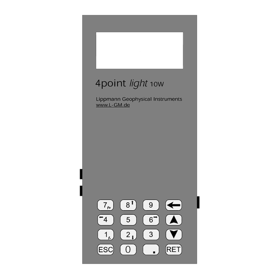
Description of the 5 Description of the instrument Fig. 5.1: Earth resistivity meter 4point light 10W: Top view (left) and side view (right) Number Function Display Serial interface RS232 Keypad 0 V-connector +12 V-connector A, Connector for electrode A ... -
Page 20: Commissioning
An automatic charging device is integrated in the instrument. This device allows recharging the internal batteries by using an external voltage source. For automatic charging “Quick charge“ must be activated in the device settings. ➔ 8.10 Settings, page 87 Page 20 of 130 Operating instructions 4point light 10W (V 4.58) -
Page 21: Automatic Charging
The instrument will acquire resistivity data in five different modes: ▪ VerticalElectricalSounding (VES) The VES-mode comprises the classical 4-electrode resistivity soundings like Schlumberger, Wenner, Dipole-Dipole and Pole-Pole ▪ MAPping (MAP) Operating instructions 4point light 10W (V 4.58) Page 21 of 130... -
Page 22: Calibration
(of the order of < 5 microvolts) at MN with high accuracy. Repeatedly performing a full calibration is recommended for high resolution IP measurements. ➔ For calibration instructions refer to 16.4 Calibration, page 22 Page 22 of 130 Operating instructions 4point light 10W (V 4.58) -
Page 23: Connection To The Pc
6. Select "Test GPRS" from the "MISC" menu The instrument checks if GPRS works. If the test fails, please repeat it once or twice. If the test fails more than three times, GPRS does not work. Operating instructions 4point light 10W (V 4.58) Page 23 of 130... -
Page 24: Avoiding Mistakes
Connect a fifth electrode to the GND terminal and use it close to the instrument Always use the GND electrode when operating the instrument with active external electrodes Page 24 of 130 Operating instructions 4point light 10W (V 4.58) -
Page 25: Operation
4.8 V, the rechargeable batteries must be reloaded before operating the instrument. For this purpose the instrument has to be connected to an external voltage source (10 - 15 V). ➔ 6.1 Power supply, page 20 ➔ 8.10 Settings, page 87 Operating instructions 4point light 10W (V 4.58) Page 25 of 130... -
Page 26: Switch Off The Instrument
Tab. 7.2: Multiple functions of several keys Multiple functions: Depending on the program mode, several keys serve multiple functions. ➔ 8.2 VES mode, page 29 ➔ 8.3 Mapping mode, page 38 Page 26 of 130 Operating instructions 4point light 10W (V 4.58) - Page 27 Key [1] is assigned to [blank] and the special characters + - _ / @ § $ % Key [1] is assigned to the special characters ! ( ) # + * = Operating instructions 4point light 10W (V 4.58) Page 27 of 130...
-
Page 28: Menu Navigation
Settings of the instrument MISC miscellaneous (calibration, test GPRS, FTP, GSM) INFO Information Battery Display of battery voltage, recharge battery when < 4.8 V! Tab. 8.1: Main menu – menu items Page 28 of 130 Operating instructions 4point light 10W (V 4.58) -
Page 29: Ves Mode
“Settings“ “Acquisition“. But unless you are not very familiar with the instrument, leave this parameter at the value the instrument was delivered (0.5 sec). ➔ 8.10.4 Acquisition, page 94 Operating instructions 4point light 10W (V 4.58) Page 29 of 130... -
Page 30: Measurement - Schlumberger Mode
Schlumberger measurements. Navigation through the records now is possible. SCHLUMB REC5 4.16Hz 0.1m 0.01m 0.00323 Ohm*m -12.3mrad 4mrad Fig. 8.5: Data browser for Schlumberger measurement results Page 30 of 130 Operating instructions 4point light 10W (V 4.58) - Page 31 7. Click [RET] to create a new record The display shows the editable parameters: SCHLUMB REC5 4.16Hz L/2 [m]: 0.1 A/2 [m]: 0.01 AutoF:Off AutoL:Off Fig. 8.6: Schlumberger and Half-Schlumberger mode – measurement parameters Operating instructions 4point light 10W (V 4.58) Page 31 of 130...
- Page 32 L/2 decrement / increment (only activated if AutoL On) 4,16 Hz [1] / [7] Frequency decrement / increment (only activated, if AutoF Off) Tab.. 8.7: Differing key assignments 8. Edit measurement parameters Page 32 of 130 Operating instructions 4point light 10W (V 4.58)
- Page 33 Tab. 8.9: Navigation through Schlumberger measurement results In AUTO mode the measurement ends as soon as the error of U0 and U90 falls below the preset value. ➔ 8.2.3 Automatic mode, page 35 Operating instructions 4point light 10W (V 4.58) Page 33 of 130...
-
Page 34: Measurement Parameters For Additional Geometries
Set A, range 1 mm ‒ 10 000 m (dipole length) A (m) AutoF: Off Set AutoF (for differing key assignment please refer to Tab. 8.7 and Tab. 8.8) Tab. 8.11: Editable measurement parameters for Dipole-Dipole mode Page 34 of 130 Operating instructions 4point light 10W (V 4.58) -
Page 35: Automatic Mode
If "Auto ON" was selected, the instrument will enter the menu "Auto Settings". At this point you set the minimum input voltage and the termination criteria for the measurement, e. g. the error of U0 / U90 and the maximum number of averages. Operating instructions 4point light 10W (V 4.58) Page 35 of 130... -
Page 36: Output
Data transmission is either in ASCII or binary format. For transmission in binary format the program Com4Point is necessary. VES OUTPUT Single File All Files Fig. 8.11: VES output Page 36 of 130 Operating instructions 4point light 10W (V 4.58) - Page 37 3. Select file number with [] and [] 4. Confirm with [RET] Data transfer starts. After selection of “All Files“ all measured files are immediately transferred to the PC. All Files Operating instructions 4point light 10W (V 4.58) Page 37 of 130...
-
Page 38: Mapping Mode
Data are recorded as voltage and current only, no apparent resistivity is calculated. ➔ 8.3.1 Standard mapping, page 40 Page 38 of 130 Operating instructions 4point light 10W (V 4.58) - Page 39 In mapping mode a closed AB circuit indicates, whether the electrodes are in place or not. The transmitter of the instrument therefore is always ON and the AB electrodes are under power. Operating instructions 4point light 10W (V 4.58) Page 39 of 130...
-
Page 40: Standard Mapping
Input auto parameters Data browser Click [RET] Measurement Last position? Pull electrodes Go to next position Place electrodes Auto mode on? Fig. 9.19: Sequence of operation in standard mapping Page 40 of 130 Operating instructions 4point light 10W (V 4.58) - Page 41 Function File number (0 … 1) File No: 0 Auto mode: ON Automatic mode ON/OFF Empty Status line: file is empty Tab. 8.17: Standard mapping “Run” – menu items Operating instructions 4point light 10W (V 4.58) Page 41 of 130...
- Page 42 If the file of the selected file number is empty (status „Empty“), grid parameters have to be defined: New Grid 4.16Hz Xmax: 0 (1..255) Ymax: 0 (1..255) Free: 41345 Samples Fig. 8.20: “New Grid” – Definition of a new grid Page 42 of 130 Operating instructions 4point light 10W (V 4.58)
- Page 43 X- and Y-direction, L the distance of the mobile electrodes. One has: dX, dY, L > 0 New dX, dY, L dX [m]: dY [m]: [m]: Fig. 8.21: “New dX, dY, L“– definition of mapping geometry Operating instructions 4point light 10W (V 4.58) Page 43 of 130...
- Page 44 Error 0.2% MaxAv Fig. 8.22: Standard mapping “Auto Settings“ If in the standard mapping menu "Auto mode OFF" was selected, you immediately enter the data browser (see below). Page 44 of 130 Operating instructions 4point light 10W (V 4.58)
- Page 45 Use the current grid point and start a new measurement with [RET] (the displayed record/dataset will be overwritten) rdy X23.45 Y23.45 100mA Avg99 4.16 U0 :1234.55mV 0.1% U90: 10.22uV 13.5% Fig. 8.23: Standard mapping: “Data browser“ Operating instructions 4point light 10W (V 4.58) Page 45 of 130...
- Page 46 Cancel, return to the standard mapping menu Tab. 8.27: Navigation through the standard mapping “Data browser” Start measurement 1. Select grid point or use the current grid point 2. Start measurement with [RET] Page 46 of 130 Operating instructions 4point light 10W (V 4.58)
- Page 47 Before data transfer the terminal program has to be started → Start Com4point on the PC → Set Com4point into receive mode → Start data transfer from the instrument to the PC Operating instructions 4point light 10W (V 4.58) Page 47 of 130...
- Page 48 3. Select file with[] and [] 4. Confirm input with [RET] Data transfer starts. After selection of “All Files“ All Files all measured files are immediately transmitted to the PC. Page 48 of 130 Operating instructions 4point light 10W (V 4.58)
-
Page 49: Multimapping
VES MAP RMT TOM MON CONTACT SP DELETE SETTINGS MISC INFO Battery: 5.52V Fig. 8.29: Main menu 1. Select „MAP“ from the main menu with [] and [] 2. Confirm selection with [RET] Operating instructions 4point light 10W (V 4.58) Page 49 of 130... - Page 50 File No: 2 Auto mode: ON Automatic mode ON/OFF Empty Status line: file is empty Tab. 8.29: Multimapping –menu items In multimapping mode data are saved to an empty file only! Page 50 of 130 Operating instructions 4point light 10W (V 4.58)
- Page 51 [RET] Continue [ESC] Cancel Tab. 8.32: Navigation through the menu “New Grid“ Once the frequency is selected, it is fixed for this file and cannot be changed afterwards! Operating instructions 4point light 10W (V 4.58) Page 51 of 130...
- Page 52 Select Xmax, Ymax or L [] Delete character [0] … [9] Numerical input or Xmax, Ymax or L [RET] Continue [ESC] Cancel Tab. 8.34: Navigation through the menu “New dX, dY, L“ Page 52 of 130 Operating instructions 4point light 10W (V 4.58)
- Page 53 Sequence of electrodes to be measured next (A-B-M-N) Number of averages f4.2 Frequency Automatic mode (or manual) In-phase voltage 0.1% Error Out-of-phase voltage 13,5% Error Tab. 8.35: Multimapping data browser – menu items Operating instructions 4point light 10W (V 4.58) Page 53 of 130...
- Page 54 Fig. 8.38 Muttimapping parameter set Menu item Function Set: 0 Number of parameter set Line: 3 Cursor position (line) A4 B0 M3 N0 Electrode combinations Tab. 8.37: Multimapping parameter set Page 54 of 130 Operating instructions 4point light 10W (V 4.58)
- Page 55 → Start Com4point on the PC → Set Com4point into receive mode → Start data transfer from the instrument to the PC MULTI-MAPPING OUTPUT Single File All Files Fig. 8.39: Data transfer Operating instructions 4point light 10W (V 4.58) Page 55 of 130...
-
Page 56: Automatic Mode
4. As soon as the preset number of averages is reached, data are stored 5. At the end of a measurement an acoustic signal sounds 6. One step decrement of output current Page 56 of 130 Operating instructions 4point light 10W (V 4.58) - Page 57 12. At the end of a measurement an acoustic signal sounds 13. Coordinates are incremented. If the circuit is not closed, the measurement will be restarted. Operating instructions 4point light 10W (V 4.58) Page 57 of 130...
-
Page 58: Remote Mode
In phase voltage State of power supply for external electrodes on/off Out of phase voltage ASCII Setting of data transmission protocol (ASCII/binary) Tab. 8.40: Display during measurement in remote mode Page 58 of 130 Operating instructions 4point light 10W (V 4.58) -
Page 59: Sending Commands To The Instrument
Current level 8: 100 mA Software version External voltage Output data format ASCII (preset) Output data format binary Perform single measurement Measure transmitter output voltage Measure battery voltage Measure self-potential Continuous measurement ON Operating instructions 4point light 10W (V 4.58) Page 59 of 130... -
Page 60: Sending Commands To The Electrodes
Tab. 8.42: Remote instructions for electrodes The electrode commands always have to be sent completely (2 Bytes). The instrument will react on further commands only if the second Byte was received. Page 60 of 130 Operating instructions 4point light 10W (V 4.58) -
Page 61: Possible Error Messages
Ext. o. int. voltage o. k.? Send „k“ Send „j“ Send command Current okay? Ext. Voltage o. k.? Send „l“ Send „j“ Send command Fig. 8.44: Reaction on current changes Operating instructions 4point light 10W (V 4.58) Page 61 of 130... - Page 62 Int. and ext. voltage below threshold Tab. 8.45: Transmitter is switched on – error messages For further troubleshooting please refer to chapter ➔ 9.2 Error messages in remote mode, page 108 Page 62 of 130 Operating instructions 4point light 10W (V 4.58)
-
Page 63: Tomography Mode
Continue Continue with an incomplete data acquisition file Output Transfer of the acquired data to the PC Remote control of tomography data acquisition Tab. 8.46: Tomography – menu items Operating instructions 4point light 10W (V 4.58) Page 63 of 130... -
Page 64: Load
Parameter set is loaded via the serial interface... Receive Parameter Parameter set: 2 Header ok..Finshed! 150 sets Fig. 8.50: Data transfer is successfully finished 5. Back to the tomography menu with [RET] or [ESC] Page 64 of 130 Operating instructions 4point light 10W (V 4.58) -
Page 65: Show
F:8.33 Frequency (Hz) V:50.00 Voltage (V) Number of averages Er:3.0 Tolerated error (%) D:2.000 Distance of electrodes (m) First electrode L:100 Last electrode Tab. 8.47: Parameters , page 2 Operating instructions 4point light 10W (V 4.58) Page 65 of 130... -
Page 66: Delete
2. Confirm with [RET] Delete parameter? <RET> Delete <ESC> Abort Fig. 8.54: Delete ALL parameter sets 3. Delete all parameter sets witch [RET] 4. Back to the tomography menu with [ESC] Page 66 of 130 Operating instructions 4point light 10W (V 4.58) -
Page 67: Run
6. Move to the next line with [] and [] 7. Confirm input with [RET] Measurement param. Min. volt[mV]: 20.00 Max. error[%]: 0.1 Avg:8 Frq:2.08 Fig. 8.57: Edit measurement parameters Operating instructions 4point light 10W (V 4.58) Page 67 of 130... - Page 68 In-phase receiver voltage U0 0.06 % Error value (%) Number of averages U90 87.79 uV Out-of-phase receiver voltage U90 4.5 % Error value (%) Tab. 8.51: Display during measurement Page 68 of 130 Operating instructions 4point light 10W (V 4.58)
-
Page 69: Continue
Fig. 8.61: Status of measurement is displayed The measurement can be cancelled at any time by clicking [ESC]. After measurement the program automatically switches back to the tomography menu. Operating instructions 4point light 10W (V 4.58) Page 69 of 130... -
Page 70: Output
Select “Rmt” from the tomography menu with [] and [] 2. Confirm selection with [RET] Remote mode <RET> Activate <ESC> Cancel Fig. 8.64: Remote mode 3. Activate remote mode with [RET] 4. Deactivate remote mode with [ESC] Page 70 of 130 Operating instructions 4point light 10W (V 4.58) -
Page 71: Monitoring Mode
FTP server after measurement Continue GPRS Continue interrupted data acquisition; data blocks are transmitted via GRPS modem to a FTP server after measurement Tab. 8.52: Monitoring – menus items Operating instructions 4point light 10W (V 4.58) Page 71 of 130... -
Page 72: Load
The instrument waits for a parameter set which is transferred via the serial interface. Receive Parameter Parameter set: 2 Ready for data..Fig. 8.68: Load parameter Data are transferred. Page 72 of 130 Operating instructions 4point light 10W (V 4.58) -
Page 73: Edit
Menu item Function Set: 0 Number of parameter set Line: 1/4 Cursor position: in line 1 of 4 A4 B0 M3 N0 Electrode combination Tab. 8.53: Edit – menu items Operating instructions 4point light 10W (V 4.58) Page 73 of 130... -
Page 74: Delete
Clicking [RET] will delete ALL parameter sets. The parameter sets cannot be deleted individually. Delete parameter? <RET> Delete <ESC> Abort Delete ALL parameter sets 1. Delete all parameter sets witch [RET] 2. Back to the monitoring menu with [ESC] Page 74 of 130 Operating instructions 4point light 10W (V 4.58) -
Page 75: New
Minimum required receiver voltage Max. error (%) Maximum permitted error value for U0 Avg: 8 Maximum numbers of averages Frq: 2.08 Measurement frequency Tab. 8.55: Measurement parameters – menu items Operating instructions 4point light 10W (V 4.58) Page 75 of 130... -
Page 76: Operating Instructions 4Point Light 10W (V 4.58
Selection of A, B, M, N or next line [] Delete character [0] … [9] Input of numerical values for A, B, M and N [RET] Confirm input and continue Tab. 8.58: Navigation through the electrode combinations Page 76 of 130 Operating instructions 4point light 10W (V 4.58) -
Page 77: Run/Rungprs
Minimum required receiver voltage Max. error [% Maximum permitted error value for U0 Avg: 8 Maximum numbers of averages Frq: 2.08 Measurement frequency Tab. 8.59: Measurement parameters – menu items Operating instructions 4point light 10W (V 4.58) Page 77 of 130... -
Page 78: Operating Instructions 4Point Light 10W (V 4.58
7. Set monitoring intervals by using the numerical keys. Format of monitoring interval: „hh.mm.ss“ 8. Confirm input with [RET] Run monitoring File: 4 n: 1234 End in: 1790d 5h Empty! Fig. 8.80: Available memory Page 78 of 130 Operating instructions 4point light 10W (V 4.58) -
Page 79: Operating Instructions 4Point Light 10W (V 4.58
External supply voltage Tab. 8.61: Waiting state – explanation 11. Wait until data acquisition starts f8.33 100u 8 /57 U0 34.78mV 0.06% U90 87.79uV 4.5% Fig. 8.82: Display during data acquisition Operating instructions 4point light 10W (V 4.58) Page 79 of 130... -
Page 80: Continue/Continuegprs
1. Select file of cancelled data acquisition with [] and [] 2. Confirm selection with [RET] Monitoring 75 at 14.10.2008 17:20:00 14.10.2008 16:21:46 18.2C i5.25 e12.45 V Fig. 8.84: Waiting state Page 80 of 130 Operating instructions 4point light 10W (V 4.58) -
Page 81: Output
3. Select file number with [] und [] The status line shows date and time of the measurement 4. Start data transfer with [RET] Output tomography Please wait... Fig. 8.86: Data transfer is running Operating instructions 4point light 10W (V 4.58) Page 81 of 130... -
Page 82: Gprs
For analysis of potential problems any single step of the connection establishment will be displayed during the tests. In case of problems the ➔ single steps may last up to five minutes. 8.11 Misc, page 98 Page 82 of 130 Operating instructions 4point light 10W (V 4.58) -
Page 83: Operating Instructions 4Point Light 10W (V 4.58
In case of transfer problems data are stored until the memory is full. The measurement will not stop, but the instrument overwrites already measured data beginning with the first data block of the current measurement file. Operating instructions 4point light 10W (V 4.58) Page 83 of 130... -
Page 84: Contact
Output Voltage: Output voltage 0.31 Hz: Output frequency (selectable) 1.0 mA Output current (selectable) 164.23 V Output voltage (displayed) 164.23 kOhm Contact resistance Tab. 8.64: Contact – menu items Page 84 of 130 Operating instructions 4point light 10W (V 4.58) -
Page 85: Operating Instructions 4Point Light 10W (V 4.58
1. Select “SP” from the main menu with [] and [] 2. Confirm selection with [RET] Self potential 0.0344 V <ESC> Exit Fig. 8.90: Measured SP The measured SP is displayed. Transmitter is OFF. Operating instructions 4point light 10W (V 4.58) Page 85 of 130... -
Page 86: Delete
2. Confirm selection with [RET] Delete all data? <BS> Delete <ESc> Abort Fig. 8.92: Delete 3. Delete data with [] All data of the instrument are deleted. 4. Exit the menu with [ESC] Page 86 of 130 Operating instructions 4point light 10W (V 4.58) -
Page 87: Settings
Set parameters for data acquisition, select country specific frequencies Save Output of internal parameter via the serial interface Load Loading internal parameter via the serial interface Tab. 8.66: Settings – menu items Operating instructions 4point light 10W (V 4.58) Page 87 of 130... -
Page 88: Device
Fig. 8.96: Set current date and time Key assignment Reaction [0] … [9] Input numerical values [RET] Confirm and save input [ESC] Cancel input, go back to the settings menu Page 88 of 130 Operating instructions 4point light 10W (V 4.58) -
Page 89: Operating Instructions 4Point Light 10W (V 4.58
Under the menu item “Startup” you select the startup mode of the instrument Startup . This is the mode the instrument changes to after starting the instrument. Possible modes are “Main menu”, “Remote” and “Monitoring”. Operating instructions 4point light 10W (V 4.58) Page 89 of 130... -
Page 90: Operating Instructions 4Point Light 10W (V 4.58
Tom. wait Tomography Wait for Key: no Fig.. 8.100: Tomography mode: activate/deactivate “response to keystroke” 1. Select YES or NO with [] 2. Save changes and quit menu with [RET] Page 90 of 130 Operating instructions 4point light 10W (V 4.58) -
Page 91: Communication
Select data format: ASCII or BINARY ASCII: Point TAB. Select ASCII format for numerical output and separators Baud rate: 19200 Set baud rate to PC Tab. 8.72: Serial – menu items Operating instructions 4point light 10W (V 4.58) Page 91 of 130... -
Page 92: Operating Instructions 4Point Light 10W (V 4.58
2. Enter PIN and context by using the alphanumerical keys 3. Confirm selection with [RET] Under the menu item “FTP” the access data for the FTP server are set. Page 92 of 130 Operating instructions 4point light 10W (V 4.58) -
Page 93: Operating Instructions 4Point Light 10W (V 4.58
“Context” is not valid: In this case no data transfer is possible anymore. → If measurements nearby a national border are to be performed, essentially select an individual provider! Operating instructions 4point light 10W (V 4.58) Page 93 of 130... -
Page 94: Service
In Europe or other countries with 50 Hz mains frequency measurements at 10 Hz result in strong interference signals. These signals interfere with the measurement. → Never use 10 Hz in Europe or in any other countries with 50 Hz mains frequency. Page 94 of 130 Operating instructions 4point light 10W (V 4.58) -
Page 95: Operating Instructions 4Point Light 10W (V 4.58
Geometry: P/DEK P/DEK (Points per decade) P/DEK is the number of values for L/2 ➔ 8.2 VES mode, page 29 in AutoL mode Tab. 8.78: Acquisition parameter– menu items Operating instructions 4point light 10W (V 4.58) Page 95 of 130... -
Page 96: Operating Instructions 4Point Light 10W (V 4.58
Mains noise only will be sufficiently suppressed if it is an odd multiple of the measurement frequency. So do not use 10 Hz in a 50 Hz mains environment! Page 96 of 130 Operating instructions 4point light 10W (V 4.58) -
Page 97: Save
Under the menu item “Load” internal parameters will be loaded via the serial interface.. RECEIVE PARAMETER Calibration Settings Fig. 8.111: Load menu 1. Select menu item by clicking [] or [] 2. Confirm selection with [RET] Parameters are loaded to the instrument Operating instructions 4point light 10W (V 4.58) Page 97 of 130... -
Page 98: Misc
4. Confirm selection with [RET] Error numbers concerning the data transfer between the instrument and the FTP-Server are listed in the appendix. ➔ 10.3 Monitoring GPRS – error numbers, page 121 Page 98 of 130 Operating instructions 4point light 10W (V 4.58) -
Page 99: Provider
- DE",,"26207"; Fig.. 8.115: Provider list The display shows the provider name, the provider ID and the current status. Individual data are separated by commas, individual datasets (providers) by semicolons. Operating instructions 4point light 10W (V 4.58) Page 99 of 130... -
Page 100: Calibration
0. By intentionally shorting M and N the instrument can determine the offset voltage and subtract this voltage for all subsequent measures. There are two possibilities of calibration: ▪ Offset calibration ▪ Full calibration Page 100 of 130 Operating instructions 4point light 10W (V 4.58) -
Page 101: Operating Instructions 4Point Light 10W (V 4.58
Fig. 8.117: Frequency and number of averages Menu item Function Frequency: 0.26 – 30 Hz/ALL Frequency: 1.25 Hz Averages: 16 (8 … 128) Number of averages Tab. 8.85: Offset calibration menu Operating instructions 4point light 10W (V 4.58) Page 101 of 130... -
Page 102: Operating Instructions 4Point Light 10W (V 4.58
U90 0.02 % Typical error in % Tab. 8.87: Offset calibration menu Key assignment Reaction [ESC] Cancel [RET] End, display and save values Tab. 8.88: Navigation during offset measurement Page 102 of 130 Operating instructions 4point light 10W (V 4.58) -
Page 103: Operating Instructions 4Point Light 10W (V 4.58
Calibration” the value of the reference resistor can be changed. This change of the resistor value may lead to instrument damage or total loss during calibration. → Do not change the value of the reference resistor! Operating instructions 4point light 10W (V 4.58) Page 103 of 130... -
Page 104: Operating Instructions 4Point Light 10W (V 4.58
Tab. 8.91: Navigation “Full Calibration” 4. Select frequency with [1] and [7] 5. Select number of averages with [] and [] 6. Continue with [RET] ALL: Automatic calibration of all frequencies Page 104 of 130 Operating instructions 4point light 10W (V 4.58) -
Page 105: Operating Instructions 4Point Light 10W (V 4.58
OFFSET: Ready 4.16Hz I: 0 mA +123.1 uV 5.6% U90 - 5.23 uV Fig. 8.123: Display of measured offset voltages 8. Save calibration values with [RET] or cancel calibration with [ESC] Operating instructions 4point light 10W (V 4.58) Page 105 of 130... -
Page 106: Operating Instructions 4Point Light 10W (V 4.58
Averaged voltage U0 and averaged voltage U90 are displayed: GAIN: Ready 4.16Hz I: 5mA 11.00 Ohm 261.06mV 0.1% 5.23 mV 0.2% Fig. 8.125: Display of gain calibration results 10. End of calibration, save measurement values with [RET] Page 106 of 130 Operating instructions 4point light 10W (V 4.58) -
Page 107: Operating Instructions 4Point Light 10W (V 4.58
8.11.2.3 Reset Calibration RESET CALIBRATION <RET> Okay <ESC> Abort Fig. 8.126: Reset calibration 1. Reset Calibration confirm with [RET] Calibration values are reset: gain to 1.0, offsets to 0.0. Operating instructions 4point light 10W (V 4.58) Page 107 of 130... -
Page 108: Troubleshooting
Output current does not meet the defined target A list of monitoring GPRS error numbers is supplied in the appendix ➔ 10.3 Monitoring GPRS – error numbers, page 121 Page 108 of 130 Operating instructions 4point light 10W (V 4.58) -
Page 109: Appendix
Offset U0, Offset U90, A, B Definition of A and B (measurement current = 5 mA): − − = voltage at ADC with reference resistor, transmitter ON 0,ref Operating instructions 4point light 10W (V 4.58) Page 109 of 130... -
Page 110: Error Definition
− Typical error percentage: Error resistivity = error (U0) in % 1000 Error phase: [mrad] where Page 110 of 130 Operating instructions 4point light 10W (V 4.58) -
Page 111: Data Formats
1.0000 0.000 1.000 81.44725 0.00341 1.0000 0.000 1.300 81.44818 0.00353 1.0000 0.000 0.200 81.44738 0.00307 1.0000 0.000 0.700 81.44757 0.00261 1.0000 0.000 2.900 Tab. 10.4: Mapping – results file Operating instructions 4point light 10W (V 4.58) Page 111 of 130... -
Page 112: Multimapping
18,03635 -0,00268 0,0 50,0 18,03753 0,00027 0,0 255,0 0 1 7,000 70,60034 0,01135 0,0 46,0 70,59625 0,00858 0,0 183,0 70,60205 0,01310 0,0 123,0 Tab. 10.7: Multimapping – results file Page 112 of 130 Operating instructions 4point light 10W (V 4.58) -
Page 113: Index
U0 (%) 255,0 error U90 (%) Tab. 10.9: Multimapping data block – examples and comment U0, U90, error U0, error U90 will be repeated for each electrode configuration. Operating instructions 4point light 10W (V 4.58) Page 113 of 130... -
Page 114: Tomography
Pole Dipole 25.0 Wenner 0.31 Dipole-Dipole 0.62 Pole-Pole 1.25 Tomography- type of measurement 10.0 15.0 30.0 Tomography - frequency code Tab. 10.11: Tomography – frequency code and type of measurement Page 114 of 130 Operating instructions 4point light 10W (V 4.58) -
Page 115: Operating Instructions 4Point Light 10W (V 4.58
Tab. 10.12: Tomography – results file with parameters and measured data Comment electrode A electrode B electrode M electrode N 46.30558 U0 [mV] -0.01825 U90 [mV] 0.100 I [mA] Tab. 10.13: Tomography record – examples and comment Operating instructions 4point light 10W (V 4.58) Page 115 of 130... -
Page 116: Monitoring
25.0 Wenner 0.31 Dipole-Dipole 0.62 Pole-Pole 1.25 Monitoring – type of measurement 10.0 15.0 30.0 Monitoring – frequency code Tab. 10.15: Monitoring – frequency code and type of measurement Page 116 of 130 Operating instructions 4point light 10W (V 4.58) -
Page 117: Operating Instructions 4Point Light 10W (V 4.58
Appendix Results file Operating instructions 4point light 10W (V 4.58) Page 117 of 130... -
Page 118: Operating Instructions 4Point Light 10W (V 4.58
Appendix Data Comment Page 118 of 130 Operating instructions 4point light 10W (V 4.58) -
Page 119: Operating Instructions 4Point Light 10W (V 4.58
47.14586 -0.00481 1.000 0.0 27 0 * measurement 3 date/time 47.14242 0.01214 1.000 0.0 3 0 * temperature 47.13429 -0.00044 1.000 0.0 68 0 * external power supply (V) Operating instructions 4point light 10W (V 4.58) Page 119 of 130... -
Page 120: Operating Instructions 4Point Light 10W (V 4.58
I (mA) error U0 (%) Error U90 (%) transmitter voltage (V) 47.15061 U0 (mV) Tab. 10.17: Monitoring record – examples and comment These data are listed for each electrode configuration Page 120 of 130 Operating instructions 4point light 10W (V 4.58) -
Page 121: Monitoring Gprs - Error Numbers
- emergency calls only network personalization PIN required network personalization PUK required network subset personalization PIN required network subset personalization PUK required service provider personalization PIN required Operating instructions 4point light 10W (V 4.58) Page 121 of 130... -
Page 122: Operating Instructions 4Point Light 10W (V 4.58
DN time-out in opening socket cannot open socket remote disconnected or time-out connection failed tx error already listening Page 122 of 130 Operating instructions 4point light 10W (V 4.58) -
Page 123: Operating Instructions 4Point Light 10W (V 4.58
FTP error no “CONNECT” 9002 FTP error no “NO CONNECT” 9003 9004 Time out on sending data to the modem (XON/XOFF) Tab. 10.18: Monitoring GPRS – list of error numbers Operating instructions 4point light 10W (V 4.58) Page 123 of 130... -
Page 124: Installing New Software
6. select the new program file which is to be downloaded to the instrument 7. switch on the instrument – download starts automatically 8. terminate the program CVMegaload after download. Fig. 10.1: Download is carried out Fig. 10.2:Download is finished Page 124 of 130 Operating instructions 4point light 10W (V 4.58) -
Page 125: Working With Hterm
8.10.2 Communication, page 91 2. Adjust the parameters COM “port”, “baud rate”, “data bits”, “stop bits” and “parity”! 3. Connect HTerm and the serial interface by clicking on the button [Connect] Operating instructions 4point light 10W (V 4.58) Page 125 of 130... -
Page 126: Operating Instructions 4Point Light 10W (V 4.58
A dump has to be transferred. The following steps have to be carried out: 1. Adjust parameters in the terminal program 2. Switch to the 4point light 10W 3. Start data transfer under “Settings”, “Save”, “Dump” The process may take up to 10 minutes. The instrument displays the status of the transfer. -
Page 127: Technical Data
Measurement speed 1,5 sec / measured value AD-converter 24 Bit Amplifier Lock-in-amplifier with in-phase/out-of-phase detection Transmitter cable Crosstalk reduction Very high suppression at 16,66 Hz, 50 Hz, 60 Hz Operating instructions 4point light 10W (V 4.58) Page 127 of 130... -
Page 128: Operating Instructions 4Point Light 10W (V 4.58
0 °C … 50 °C (32 °F …122 °F) Range of temperature Humidity < 85 % Storage temperature -20 °C … +70 °C (-4 °F …+158 °F) Storage of the instrument Page 128 of 130 Operating instructions 4point light 10W (V 4.58) -
Page 129: Index
..........18 protocol ......refer to error protocol frequencies ..........100 provider ............. 97 FTP..........25, 97, 102 provider ID ......... 97, 103 General Packet Radio Service refer to GPRS Operating instructions 4point light 10W (V 4.58) Page 129 of 130... - Page 130 VES ............31 voltage correction ........113 voltage source ........... 22 safety instructions ........9 Schlumberger ........17, 31 self-potential ..........89 serial interface ........... 25 Wenner ..........17, 36 Page 130 of 130 Operating instructions 4point light 10W (V 4.58)
Need help?
Do you have a question about the 4point light and is the answer not in the manual?
Questions and answers