Denon DP-500M Service Manual
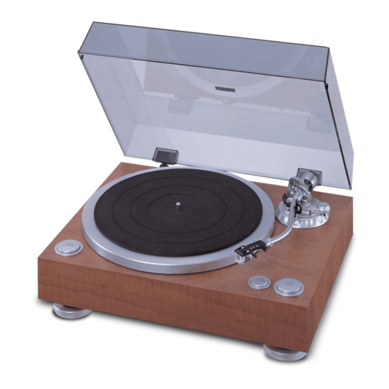
Direct drive turn table system
Hide thumbs
Also See for DP-500M:
- Operating instructions manual (8 pages) ,
- Specifications (1 page) ,
- Product sheet (1 page)
Table of Contents
Advertisement
DIRECT DRIVE TURN TABLE SYSTEM
●
For purposes of improvement, specifications and
design are subject to change without notice.
●
Please use this service manual with referring to the
operating instructions without fail.
●
Some illustrations using in this service manual are
slightly different from the actual set.
SERVICE MANUAL
MODEL
Denon Brand Company, D&M Holdings Inc.
DP-500M
注 意
サービスをおこなう前に、このサービスマニュアルを
必ずお読みください。本機は、火災、感電、けがなど
に対する安全性を確保するために、さまざまな配慮を
おこなっており、また法的には「電気用品安全法」に
もとづき、所定の許可を得て製造されております。
従ってサービスをおこなう際は、これらの安全性が維
持されるよう、このサービスマニュアルに記載されて
いる注意事項を必ずお守りください。
本機の仕様は性能改良のため、予告なく変更すること
●
があります。
補修用性能部品の保有期間は、製造打切後8年です。
●
修理の際は、必ず取扱説明書を参照の上、作業を行っ
●
てください。
本文中に使用しているイラストは、説明の都合上現物
●
と多少異なる場合があります。
For U.S.A. model
Ver. 5
Please refer to the
MODIFICATION NOTICE.
X0193 V.05 DE/CDM 0712
Advertisement
Table of Contents

Related Manuals for Denon DP-500M


Summary of Contents for Denon DP-500M
- Page 1 Please use this service manual with referring to the ● てください。 operating instructions without fail. 本文中に使用しているイラストは、説明の都合上現物 ● Some illustrations using in this service manual are ● と多少異なる場合があります。 slightly different from the actual set. Denon Brand Company, D&M Holdings Inc. X0193 V.05 DE/CDM 0712...
-
Page 2: Safety Precautions
DP-500M SAFETY PRECAUTIONS The following check should be performed for the continued protection of the customer and service technician. LEAKAGE CURRENT CHECK Before returning the unit to the customer, make sure you make either (1) a leakage current check or (2) a line to chassis resistance check. - Page 3 DP-500M DISASSEMBLY ( For reassembling, do reverse manner as to disassembling.) 1. PLATTER (1) Remove mat on the platter. (2) Remove platter by both hands. 2. BOTTOM BASE ASS'Y (1) Put cabinet reversely. (2) Remove 9 screws securing the bottom base Ass’y.
- Page 4 DP-500M 3. MAIN P.W.B. ASS'Y , TONE ARM ASS'Y fastening the main P.W.B Ass’y. (1) Remove 4 screws ① (2) Unsolder 5 wires and GND wire from arm section on the output P.W.B. Ass’y. (3) Remove 3 screws ② secured the tone arm.( Hold tone arm during removing.) 4.
-
Page 5: Button Ass'y
DP-500M 5. BUTTON ASS'Y (1) Remove 6 screws ⑦ secured the plates. (2) Remove 3 screws ⑧ secured the 33/45 P.W.B. Ass’y. (3) Remove the plates from the button frame. 6. BUTTON DISASSEMBLING (1) Insert a screwdriver or similar tool into the holes ( two places ) on the bottom of button frame and push in the arrow direction firmly to remove the button from push switch. -
Page 6: Block Diagram
DP-500M BLOCK DIAGRAM... -
Page 7: Wow And Flutter
DP-500M ADJUSTMENT 1. WOW AND FLUTTER (1) Remove the platter and put cabinet reversely. (2) Remove the bottom base Ass’y. (3) Connect 2 digital volt meters or testers to CN104 of D.D. motor P.W.B.( refer to the CN104 fig.) (4) Turn ON and set the speed select switch to 33 rpm. -
Page 8: Pin Description
DP-500M SEMICONDUCTORS Only major semiconductors are shown, general semiconductors etc. are omitted to list. 主な半導体を記載しています。汎用の半導体は記載を省略しています。 IC’s MAX003 (IC303) AVCC VREF P70/AN0 P71/AN1 P72/AN2 P73/AN3 P74/AN4 P75/AN5 P76/AN6/DA0 P77/AN7/DA1 AVSS IC303 IRQ0/P80 CS3/IRQ1/P81 MAX003 CS2/IRQ2/P82 ADTRG/CS1/IRQ3/P83 CS0/P84 TCLKA/TP0/PA0 TCLKB/TP1/PA1 TCLKC/TIOCA0/TP2/PA2 TCLKD/TIOCB0/TP3/PA3... - Page 9 DP-500M NJM-2147D (IC101,102) OUT1 -IN1 OUT2 -IN2 +IN1 +IN2 HEDS9700F51 (IC103)
- Page 10 DP-500M US1881 (H11 ∼ H13) U 1 8 1 3 5 P I N O U T : P i n 1 P i n 2 G N D P i n 3 O u t p u t DTC124TS...
-
Page 11: Printed Wiring Board
PRINTED WIRING BOARD (1/2) DP-500M MAIN P.W.B. UNIT FOIL SIDE COMPONENT SIDE 33/45 P.W.B. UNIT AC P.W.B. UNIT OUTPUT P.W.B. UNIT START/STOP P.W.B. UNIT COMPONENT SIDE COMPONENT SIDE COMPONENT SIDE COMPONENT SIDE... - Page 12 PRINTED WIRING BOARD (2/2) DP-500M D. D. MOTER P.W.B. UNIT COMPONENT SIDE FOIL SIDE...
-
Page 13: Note For Parts List
DP-500M NOTE FOR PARTS LIST Part indicated with the mark " " are not always in stock and possibly to take a long period of time for supplying, or in some case supplying of part may be refused. When ordering of part, clearly indicate "1" and "I" (i) to avoid mis- supplying. -
Page 14: Parts List Of P.w.b. Unit Ass'y
DP-500M PARTS LIST OF P.W.B. UNIT ASS’Y PARTS LIST OF MAIN P.W.B. ASS'Y Ref. No. Part No. Part Name Remarks SEMICONDUCTORS GROUP IC301 941 0021 900 IC(BD4745G/BD4745G/TR) 417-HDJ2000-503 IC302 941 0021 803 IC(BA10393F/BA10393FE2,SOP-8) 417-DV330-197 IC303 941 0021 706 IC(MAX003,FP-100B) 417-DJ5500-578... - Page 15 DP-500M Ref. No. Part No. Part Name Remarks C305 958 0055 505 CERAMIC CAPACITOR(0.1uF/50V,Z,TAPING,Y5V) 413-3113-035 C306 958 0055 505 CERAMIC CAPACITOR(0.1uF/50V,Z,TAPING,Y5V) 413-3113-035 C307 958 0055 505 CERAMIC CAPACITOR(0.1uF/50V,Z,TAPING,Y5V) 413-3113-035 C308 941 0024 208 ELEC. CAPACITOR(100uF/10V,M,TAPING 5*11) 413-3113-046 C309 941 0024 703 ELEC.
- Page 16 DP-500M PARTS LIST OF OUTPUT&POWER P.W.B. ASS'Y Ref. No. Part No. Part Name Remarks CAPACITORS GROUP 958 0045 308 MEX CAPACITOR(0.1uF/250V,K,BULK) 413-PROTT1-432 958 0010 003 SPARK CAPACITOR(4700pF/250V,M,BULK,Y5V) 413-1431-104 OTHER PARTS GROUP 958 0046 404 FUSE(1A/250V,T-MARK/UL/CSA) 422-CDN12F-028 941 0022 608 WAVE FILTER...
- Page 17 DP-500M Ref. No. Part No. Part Name Remarks D114 958 0042 806 SWITCHING DIODE(1SS132/1SS133,300mw,55V,T-77) 414-3113-005 D115 958 0042 806 SWITCHING DIODE(1SS132/1SS133,300mw,55V,T-77) 414-3113-005 D116 958 0042 806 SWITCHING DIODE(1SS132/1SS133,300mw,55V,T-77) 414-3113-005 D117 958 0042 806 SWITCHING DIODE(1SS132/1SS133,300mw,55V,T-77) 414-3113-005 D118 958 0042 806...
- Page 18 DP-500M Ref. No. Part No. Part Name Remarks R144 941 0025 333 CHIP RESISTOR(1K OHM,1/8W,J,TP 0805,150V) 412-DV330-305 R145 241 2398 052 CARBON FILM RESISTOR(1K OHM J 1/6W TAPING 26mm) 412-3113-078 R146 941 0024 101 METAL FILM RESISTOR(1 OHM,1W,J,T-73) 412-DJ5500-661 R147...
- Page 19 DP-500M Ref. No. Part No. Part Name Remarks C909 941 0024 402 ELEC. CAPACITOR(2200uF/35V,M,BULK 16*25) 413-HT7016-223 C910 941 0024 402 ELEC. CAPACITOR(2200uF/35V,M,BULK 16*25) 413-HT7016-223 C911 941 0024 211 ELEC. CAPACITOR(100uF/35V,M,TAPING 8*11) 413-HMD5000-356 C912 958 0055 505 CERAMIC CAPACITOR(0.1uF/50V,Z,TAPING,Y5V) 413-3113-035 C913 941 0024 211 ELEC.
-
Page 20: Exploded View
DP-500M EXPLODED VIEW Parts List WARNING: Parts marked with this symbol have critical characteristics. Use ONLY replacement parts recommended by the manufacturer. -
Page 21: Parts List Of Exploded View
DP-500M PARTS LIST OF EXPLODED VIEW Ref. No. Part No. Part Name Remarks Q'ty 941 0015 000 CHASSIS 300-500-1024 941 0015 107 BOTTOM BASE ASS'Y 703-500-751 941 0015 301 ALUMINUM PLATTER ASS' Y 702-500-039 941 0015 204 SLIPMAT PACKING ASS' Y... -
Page 22: Rating Label
DP-500M Ref. No. Part No. Part Name Remarks Q'ty 00D 941 0056 302 RATING LABEL 501-500E3-1680A 958 0004 404 SERIES NO. LABEL 501-DV300-1067 941 0018 803 LENS 100-5500-2098 958 0009 409 CORD BUSH 100-HC1421FR-991 941 0019 572 SCREW(WPTP,3*15,CAP10) 602-500-477 941 0029 300... -
Page 23: Points Of Greasing
DP-500M POINTS OF GREASING Grease Maker Note CR-S Daizo Corporation (Nichimoly) Synthetic oil based resin-use lithium grease KF-96H Shin-Etsu Chemical Co., Ltd. Dimethyl silicone fluid 100.000mm /s... -
Page 24: Packing View
DP-500M PACKING VIEW PARTS LIST OF PACKING & ACCESSORIES Ref. No. Part No. Part Name Remarks Q'ty 958 0039 521 POLYBAG 505-DD3220-099 941 0016 902 DUST COVER ASS'Y 701-500-2913 941 0015 204 SLIPMAT PACKING ASS'Y 705-500-867 00D 941 0056 506... - Page 25 DP-500M CONNECTIONS 33/45 D. . D MOTOR C 909 CN901 C901 CN301 CN303 CN302 M A I N POWER OUTPUT BLUE WHITE RED GREEN BLACK and GND wire...
-
Page 26: Note For Schematic Diagram
DP-500M 配線図について NOTE FOR SCHEMATIC DIAGRAM ! 印の部品は安全を維持するために重要な部品です。 WARNING: 従って交換時は必ず指定の部品を使用してください。 Parts marked with this symbol have critical charac- teristics. Use ONLY replacement parts recommended by the manufacturer. 注) CAUTION: (1) 指定なき抵抗値は Ω、k は kΩ、M は MΩ を Before returning the unit to the customer, make sure you 示す。... - Page 27 DP-500M D.D. MOTOR UNIT DC UNIT C103 102P D105 R106 R107 1SS132 IC901 IC902 C110 C119 NJM7805 NJM7812 C114 0.1uF 100u/35 C101 102P 100u/35 Q103 2SD1889 D106 1SS132 7 IC101B R101 6.8K R102 NJM2147 D101 C102 102P R122 1 1W...
-
Page 28: Main Unit
DP-500M MAIN UNIT R327 C311 IC301 R317 C313 C310 C312 4.7K 100u/10 R302 R304 0.1uF R306 R314 L302 C307 C309 3.3K R305 1M R321 X301 0.1uF C302 R303 16MHz BD4745G 0.1uF 1u/50 D301 R322 R301 1SS132 IC302A R307 BA10393 C314...
Need help?
Do you have a question about the DP-500M and is the answer not in the manual?
Questions and answers