Table of Contents
Advertisement
Quick Links
Advertisement
Table of Contents

Summary of Contents for Fusionstor INVENTO SERIES
- Page 1 FUSIONSTOR INVENTO SERIES INVENTO i737e SERIES-MANUAL...
- Page 2 Fusionstor W orkstation Invento i737e Series P a g e...
- Page 3 Fusionstor reserves the right to make changes to the product described in this manual at any time and without notice. This product, including software and documentation, is the property of Fusionstor and/or its licensors, and is supplied only under a license.
- Page 4 The Fusionstor Invento i737e is a high-end system based on the Mid-Tower chassis and the Fusionstor server board. The Fusionstor Invento i737e features a unique and highly optimized design, allowing the user to install components with minimal or no use of screws or tools. The chassis is equipped with a either a 500, 865, 900 or redundant 500 Watt whisper quiet, high-efficiency power supply for superb power savings.
- Page 5 Four 3.5" HDD drive bays and four optional 2.5" HDD drive bays offer maximum storage capacity Serverboard Features At the heart of the Fusionstor Invento i737e lies the motherboard a dual processor serverboard based on the Intel® C612 chipset. Below are the main features of the motherboard.
- Page 6 The i737e is an ATX form factor chassis that can be used as a Mid- tower. The following is a general outline of the main features of the chassis. System Power The Fusionstor Invento i737e features a single 900W power supply. This power supply unit has been designed to operate at a low noise level to make it ideal for use in a workstation environment. SATA Subsystem The i737e chassis was designed to support four SATA hard drives.
- Page 7 Overview This chapter provides a quick setup checklist to get your Fusionstor Invento i737e up and running. Following these steps in the order given should enable you to have the system operational within a minimum amount of time. This quick setup assumes that your system has come to you with the processor and memory preinstalled.
- Page 8 • Ensure that the caster wheels on the workstation are locked. • Review the electrical and general safety precautions. • Use a regulating uninterruptible power supply (UPS) to protect the workstation from power surges, voltage spikes and to keep your system operating in case of a power failure.
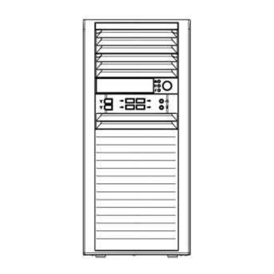
- Page 9 Overview The control panel on the Fusionstor i737e has several LEDs and two buttons. There are also two LEDs on each hard drive carrier. These LEDs keep you constantly informed of the overall status of the system and the activity and health of specific components.
- Page 10 3-4 Control Panel LEDs The control panel located on the front of the Fusionstor chassis has six LEDs that provide you with critical information related to different parts of the system. This section explains what each LED indicates when illuminated and any corrective action you may need to take.
- Page 11 3-6 Overheat/Fan Fail When this LED flashes, it indicates a chassis fan failure. When on continuously it indicates an overheat condition, which may be caused by cables obstructing the airflow in the system or the ambient room temperature being too warm. Check the routing of the cables and make sure all fans are present and operating normally.
- Page 12 The following statements are industry standard warnings, provided to warn the user of situations which have the potential for bodily injury. Should you have questions or experience difficulty, contact Fusionstor's Technical Support department for assistance. Only certified technicians should attempt to install or configure components.
- Page 13 Battery Handling Warning! There is the danger of explosion if the battery is replaced incorrectly. Replace the battery only with the same or equivalent type recommended by the manufacturer. Dispose of used batteries according to the manufacturer's instructions. Redundant Power Supplies Warning! This unit might have more than one power supply connection.
-
Page 14: Advanced Serverboard Setup
Chapter 5 Advanced Serverboard Setup This chapter covers the steps required to install the serverboard into the chassis, connect the data and power cables and install add-on cards. All serverboard jumpers and connections are also described. A layout and quick reference chart are included in this chapter for your reference. - Page 15 Processor and Heatsink Installation Warning: When handling the processor package, avoid placing direct pressure on the label area of the fan. Notes: • Always connect the power cord last and always remove it before adding, removing or changing any hardware components. Make sure that you install the processor into the CPU socket before you install the CPU heatsink.
- Page 16 15 | P a g e...
- Page 17 16 | P a g e...
- Page 18 17 | P a g e...
- Page 19 18 | P a g e...
- Page 20 Memory Support The motherboard supports up to 2 TB of LRDIMM (Load-Reduced DIMMs) or 1 TB of RDIMM (Registered DIMMs) ECC DDR4- 2400/2133/1866/1600 memory. 19 | P a g e...
- Page 21 20 | P a g e...
- Page 22 5-7 Control Panel Connectors and I/O Ports The I/O ports are color coded in conformance with the industry standards. See the picture below for the colors and locations of the various I/O ports. Back Panel Connectors and I/O Ports Back Panel I/O Port Locations and Definitions 21 | P a g e...
-
Page 23: Serverboard Details
5-8 Serverboard Details Figure.- Motherboard Layout • SAS components are not included on the motherboard Quick Reference 22 | P a g e... - Page 24 23 | P a g e...
- Page 25 24 | P a g e...
- Page 26 25 | P a g e...
- Page 27 26 | P a g e...
- Page 28 27 | P a g e...
- Page 29 28 | P a g e...
- Page 30 29 | P a g e...
- Page 31 30 | P a g e...
- Page 32 31 | P a g e...
- Page 33 32 | P a g e...
- Page 34 33 | P a g e...
- Page 35 5-13 Onboard Battery Please handle used batteries carefully. Do not damage the battery in any way; a damaged battery may release hazardous materials into the environment. Do not discard a used battery in the garbage or a public landfill. Please comply with the regulations set up by your local hazardous waste management agency to dispose of your used battery properly.
-
Page 36: Chassis Setup And Maintenance
This chapter covers the steps required to install components and perform maintenance on the chassis. Most components of the Fusionstor i737e do not require tools or screws to set them up. Those components which must be secured with screws require only a Phillips screwdriver. Print this chapter to use as a reference while setting-up your chassis. -
Page 37: Rotating The Hard Drive Cage
Rotating the Hard Drive Cage Figure. Rotating the Hard Drive Cage In order to access and install components in the chassis interior, it is necessary to rotate the hard drive cage (B). This will provide sufficient room to install and configure the chassis components. Rotating the Hard Drive Cage 1. - Page 38 The Fusionstor i737e chassis must be powered-down before hard drives can be removed from the hard drive carriers. Removing and Installing 3.5" Hard Drives 1. Power down the system and remove the power cord from the rear of the power supply. Remove the chassis side cover as described in Previous Section.
- Page 39 Removing and Installing 2.5" Hard Drives (Optional) Figure. Removing the 2.5" Hard Drives The Fusionstor i737e chassis must be powered-down before hard drives can be removed from the hard drive carriers. Removing and Installing 2.5" Hard Drives 1. Power down the system and remove the power cord from the rear of the power supply. Remove the chassis side cover as described in Previous Section.
- Page 40 11. Plug the power cord back into the power module, replace the chassis cover and power-up the system Installing a 3.5" Device (Optional) The Fusionstor i737e chassis has one 3.5" device slot, which supports an optional device, such as an all-in-one card reader.
- Page 41 1. Insert the tabs on the front bezel into the mounting holes on the front of the chassis. 2. Ensure that the cover fits snugly. This completes the installation of basic components in the Fusionstor i737e chassis Figure. Installing the Front Bezel...
-
Page 42: Power Supply
Power Supply The Fusionstor i737e chassis includes either a 500W, redundant 500W, 865W or 900W power supply. In the unlikely event that it becomes necessary to replace the power supply, follow the instructions below Figure. Removing the Power Supply Changing the Power Supply 1. - Page 43 When an option is selected in the left frame, it is highlighted in white. Often a text message will accompany it. Note: the AMI BIOS has default text messages built in. Fusionstor retains the option to include, omit, or change any of these text messages.
- Page 44 Flashing the wrong BIOS can cause irreparable damage to the system. In no event shall Fusionstor be liable for direct, indirect, special, incidental, or consequential damages arising from a BIOS update. If you have to update the BIOS, do not shut down or reset the system while the BIOS is updating to avoid possible boot failure.
-
Page 45: Memory Information
Note: The time is in the 24-hour format. For example, 5:30 P.M. appears as 17:30:00. Version: This item displays the version of the BIOS ROM used in the system. Build Date: This item displays the date when the version of the BIOS ROM used in the system was built. - Page 46 Warning: Take Caution when changing the Advanced settings. An incorrect value, a very high DRAM frequency or an incorrect BIOS timing setting may cause the system to malfunction. When this occurs, restore the setting to the manufacture default setting. 45 | P a g e...
- Page 47 46 | P a g e...
- Page 48 47 | P a g e...
- Page 49 48 | P a g e...
- Page 50 49 | P a g e...
- Page 51 50 | P a g e...
- Page 52 51 | P a g e...
- Page 53 52 | P a g e...
- Page 54 53 | P a g e...
- Page 55 54 | P a g e...
- Page 56 55 | P a g e...
- Page 57 56 | P a g e...
- Page 58 57 | P a g e...
- Page 59 58 | P a g e...
- Page 60 59 | P a g e...
- Page 61 60 | P a g e...
- Page 62 61 | P a g e...
- Page 63 62 | P a g e...
- Page 64 63 | P a g e...
- Page 65 64 | P a g e...
- Page 66 65 | P a g e...
- Page 67 66 | P a g e...
- Page 68 67 | P a g e...
- Page 69 68 | P a g e...
- Page 70 Event Logs Use this feature to configure Event Log settings 69 | P a g e...
- Page 71 70 | P a g e...
-
Page 72: Boot Settings
Boot Settings 71 | P a g e... - Page 73 72 | P a g e...
- Page 74 73 | P a g e...
-
Page 75: Save And Exit
Save & Exit 74 | P a g e... - Page 76 75 | P a g e...
- Page 77 76 | P a g e...
- Page 78 ® INDIA : Fusionstor Technologies Pvt. Ltd. Unit No. 1-2, Building No.5, Sector III, Millennium Business Park, Mahape, Navi Mumbai. Pin: 400 710. INDIA. Tel.: +91 (22) 41 577 577 EUROPE SINGAPORE Disclaimer: All specifica ons and figures are subject to change without prior no ce. Actual products may look different from the photos. All rights reserved.
Need help?
Do you have a question about the INVENTO SERIES and is the answer not in the manual?
Questions and answers