
Related Manuals for Sokkia RC-PR4

Summary of Contents for Sokkia RC-PR4
- Page 1 SURVEYING INSTRUMENTS On-demand Remote Control System RC-PR4 SYSTEM MANUAL Class 1 Laser Product...
- Page 2 S Li-ion Li-ion :This is the mark of the Japan Surveying Instruments Manufacturers Association.
- Page 3 “10.1 Standard Equipment” • The specifications and general appearance of the instrument are subject to change without prior notice and without obligation by Sokkia Topcon Co., Ltd. and may differ from those appearing in this manual. • The content of this manual is subject to change without notice.
- Page 4 HOW TO READ THIS MANUAL Symbols The following conventions are used in this manual. : Indicates precautions and important items which should be read before operations. : Indicates a cross-reference to refer to for additional information. : Indicates supplementary explanation. : Indicates an explanation for a particular term or operation.
-
Page 5: Table Of Contents
CONTENTS 1. PRECAUTIONS FOR SAFE OPERATION ....1 2. PRECAUTIONS ............3 3. LASER SAFETY INFORMATION ....... 6 4. ON-DEMAND REMOTE CONTROL FUNCTIONS ..7 Turning Operation Flow ............. 8 Measurement Flow ............9 5. SYSTEM CONFIGURATION ........12 Parts of the RC-Controller ..........12 System Configuration of the SRX/NET ...... - Page 6 CONTENTS 11. SPECIFICATIONS ............ 41 12. EXPLANATION ............44 12.1 High Accuracy with the 360° Prism ........44 13. REGULATIONS ............45...
-
Page 7: Precautions For Safe Operation
1. PRECAUTIONS FOR SAFE OPERATION For the safe use of the product and prevention of injury to operators and other persons as well as prevention of property damage, items which should be observed are indicated by an exclamation point within a triangle used with WARNING and CAUTION statements in this system manual. The definitions of the indications are listed below. - Page 8 1. PRECAUTIONS FOR SAFE OPERATION Do not use the carrying case as a footstool. The case is slippery and unstable so a person could slip and fall off it. Power Supply Warning Do not short circuit. Heat or ignition could result. Do not place articles such as clothing on the battery charger while charging batteries.
-
Page 9: Precautions
2. PRECAUTIONS Precautions • Protect instruments from heavy shocks or vibration. • Never touch the RC-Controller laser projection port or the total station beam detector. The ability of the system to perform Turning may be adversely affected. • Turn the power OFF before removing the battery from the RC-Controller. •... - Page 10 Contact your local dealer in advance. "13. REGULATIONS" • Sokkia Topcon Co., Ltd. is not liable for the content of any transmission nor any content related thereto. When communicating important data, run tests beforehand to ascertain that communication is operating normally.
- Page 11 • Sokkia Topcon Co., Ltd. cannot guarantee that all Bluetooth devices are compatible with the On- demand Remote Control System. Exceptions from responsibility •...
-
Page 12: Laser Safety Information
3. LASER SAFETY INFORMATION RC-Controller is classified as a Class 1 Laser Product according to IEC Standard Publication 60825- 1 Ed. 2.0: 2007 and United States Government Code of Federal Regulation FDA CDRH 21CFR Part1040.10 and 1040.11 (Complies with FDA performance standards for laser products except for deviations pursuant to Laser Notice No.50, dated June 24, 2007.) Laser beam is emitted from here... -
Page 13: On-Demand Remote Control Functions
4. ON-DEMAND REMOTE CONTROL FUNCTIONS The On-demand Remote Control System works as follows. A laser is emitted from the laser projection port on the RC-Controller. The total station rotates until its beam detector receives this beam. In this way the total station is able to detect the position of the RC-Controller. This operation is called "Turning". -
Page 14: Turning Operation Flow
4. ON-DEMAND REMOTE CONTROL FUNCTIONS Turning Operation Flow To perform Turning, follow the procedure below. For measurement procedure, see "4.2 Measurement Flow" 1. Point the RC-Controller laser projection port and prism in the direction of the total station and instruct the instrument to start Turning. A laser beam is emitted from the projection port. -
Page 15: Measurement Flow
4. ON-DEMAND REMOTE CONTROL FUNCTIONS • The time limit for Turning is 60 seconds from the start of Turning operation. If the operation exceeds this time limit, an error occurs. • When Auto Tracking has been selected, the SRX/NET will start tracking a moving prism once Turning to that prism has been completed. - Page 16 4. ON-DEMAND REMOTE CONTROL FUNCTIONS 4. Check that SRX/NET Bluetooth settings are made and the instrument is ready for communcation. "6.1 Settings for Bluetooth Communication" After completing the total station preparations above, the next step is to prepare the RC- Controller.
- Page 17 4. ON-DEMAND REMOTE CONTROL FUNCTIONS Height difference and slope distance The maximum measuring range depends on the height difference between the total station and the RC-Controller. The shaded area in the graph below represents the measurement range when set to Far Mode. Height difference Measurement range...
-
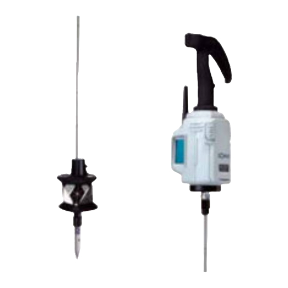
Page 18: System Configuration
5. SYSTEM CONFIGURATION Parts of the RC-Controller RC-Controller (RC-PR4) ● Laser projection Control panel port side side Bluetooth antenna Blind cap Laser projection port Battery cover Control panel Control panel ● COM1 ● COM2 ● FAR FAR button ● POWER ●... - Page 19 Strap Adjusting the circular level First attach the RC-Handle and 360° Prism ATP1 to the RC-PR4, and then attach the RC-PR4 to the instrument height adapter (AP41) etc. Holding the RC-Handle, keep the instrument level. Check the position of the bubble of the circular level. If the bubble is not off-center, no adjustment is necessary.
-
Page 20: System Configuration Of The Srx/Net
5. SYSTEM CONFIGURATION System Configuration of the SRX/NET Only instruments incorporating a handle equipped with a beam detector (RC-TS3 or RC-TS3A) can be used with the On-demand Remote Control System. Always open the beam detector cover when using the On-demand Remote Control System. •... -
Page 21: System Configuration Of The Rc-Controller
5. SYSTEM CONFIGURATION System Configuration of the RC-Controller For use with other prism types, contact your local dealer. Pin Pole Type ● RC-Handle for RC-PR4 RC-PRH4 Protector Protector pole 360° Prism ATP1 Pin pole for Adapter ATP1S SB184 pole 360° Sliding Prism... - Page 22 5. SYSTEM CONFIGURATION Range Pole Type ● RC-Controller RC-PR4 The pole reading shows the height from the bottom of the pole shoe to the Protector center of the 360° Prism (ATP1) when using the configuration shown at right. 360° Prism...
- Page 23 5. SYSTEM CONFIGURATION Attaching/Releasing the One-touch attachment ● Slide the lock release button to the right then press to release the One-touch attachment. Attaching the One-touch attachment (SB179A) to the range pole (AP67/67A) ● Attach to the pole using the following procedure. Locknut 1.
- Page 24 5. SYSTEM CONFIGURATION Adjusting position of 360° Prism (ATP1S) on pin pole (PP2) ● Pressing the release button allows the prism to slide up and down the pin pole. Release the release button to secure the prism at the desired position.
- Page 25 5. SYSTEM CONFIGURATION Connecting the 360° Prism to the RC-Controller ● Attach the 360° Prism to the RC-Controller so that the center of the RC-Controller and the sighting direction of the prism are aligned and the laser projection port is pointing in the same direction as the prism sighting direction.
-
Page 26: Settings For The Srx/Net
6. SETTINGS FOR THE SRX/NET The following settings are necessary in order to use the SRX/NET as part of the On-demand Remote Control System. For other functions and operations, see the operator's manual for your total station. For further details regarding Bluetooth communications, see "2. PRECAUTIONS Precautions concerning Bluetooth wireless technology"... - Page 27 6. SETTINGS FOR THE SRX/NET 2. Select "Slave" as the SRX/NET mode and press [OK]. Selection can also be made by tapping the icon in the status panel until a menu appears. • When communicating between a data collector and the RC-Controller using Bluetooth wireless technology, set modem for the data collector as the "Slave"...
-
Page 28: Settings For Auto Pointing And Auto Tracking
6. SETTINGS FOR THE SRX/NET Settings for Auto Pointing and Auto Tracking • Auto Pointing model does not support Auto Tracking. PROCEDURE 1. Select "Motor" in <Configuration>. Set Auto Pointing/Auto Tracking functions in the Configuration tab. For Auto Pointing only set "A.T. Setting" to "Search". - Page 29 6. SETTINGS FOR THE SRX/NET and reticle after Auto Pointing completed changes as shown below depending on the Accu. search. setting. "Fine": ± 5" (approx.) "Rapid": ± 30" to ± 10’ (depending on distance) 2. Set "Srch. method" to "R.C." in order to start Turning operation in response to a Turning command issued from the RC-Controller.
-
Page 30: Performing Turning From The Srx/Net
6. SETTINGS FOR THE SRX/NET Performing Turning from the SRX/NET It is possible to allocate SRX/NET softkeys for both designating the Turning direction, and issuing the instruction to start Turning. For allocating softkey functions, see the Series SRX or NET05AX/NET1AX Operator’s Manual ●... - Page 31 6. SETTINGS FOR THE SRX/NET [AT On] Performs Turning Performs Auto Pointing Performs Auto Tracking (Auto operation then Auto then Auto Tracking Tracking Tracking model only) When "Track" is set (Auto Tracking model only) ● "Motor" When "Track" set in "A.T. Setting" When "None"...
-
Page 32: Turning Error
6. SETTINGS FOR THE SRX/NET Turning Error When Turning fails to detect the prism, an error occurs When the laser beam from the RC-Controller is reflected off an unrelated object the SRX/NET completes Turning operation pointing at the object instead of the RC-Controller. When this happens, press [RC Cont] to nullify the current measurement position and continue Turning operation. -
Page 33: Basic Operation
7. BASIC OPERATION This section explains basic operation of the RC-Controller. Using the Battery Mount the charged battery (BDC46C). When the remaining battery power becomes low, the ● POWER Flashes. Types of power source: "10.3 Power Supply System" • Remove the battery when the instrument is not being used. •... -
Page 34: Configuring Bluetooth Connections To The Srx/Net
7. BASIC OPERATION Configuring Bluetooth Connections to the SRX/NET The RC-Controller should be set to "Master" when pairing the total station with the RC-Controller for Bluetooth wireless communication for the first time. The RC-Controller searches for the total station wireless device and initiates a connection. 1. -
Page 35: Button Operations
7. BASIC OPERATION is displayed on the status bar of When the total station companion device, the RC- Controller is currently paired to different device. Press the SEARCH button switch the pairing from the current device to the next locally available device. displayed after a brief period, press the FAR to confirm the pairing. - Page 36 7. BASIC OPERATION 7.3.2 Setting Distance Mode The FAR button is used to set the Distance Mode depending on the distance between the total station and the RC-Controller. Pressing the FAR button switches the ● FAR from Lit to Off and vice versa. Lit: Far Mode Off:...
-
Page 37: Communication Status
7. BASIC OPERATION Communication Status The Bluetooth wireless modem incorporated in the RC-Controller allows simultaneous communication between the RC-Controller and both the total station and data collector. COM1 is designed for long- range (line-of-sight distance up to 300m) communication with the total station. COM2 is for communication with data collectors. -
Page 38: Calibrating The Electronic Compass
7. BASIC OPERATION Calibrating the Electronic Compass The onboard electronic compass was calibrated before being shipped from the factory. A function within the compass will automatically perform any necessary calibration in response to changes in the magnetic field. Although this function by itself is sufficient in normal situations, when the RC-Controller becomes highly magnetized, manual calibration is necessary. - Page 39 7. BASIC OPERATION PROCEDURE Manually calibrating the compass 1. Press the POWER button while pressing the FAR button with the power switched OFF. An audio tone sounds and the RC- Controller is switched ON in calibration mode. ● FAR and ● SEARCH are Lit. 2.
- Page 40 7. BASIC OPERATION 6. Without moving the position of the RC- 1m or above Controller, rotate it 1.5 to 2 times in a horizontal direction. 7. After rotating, continue to hold the RC- Controller horizontal and press the SEARCH button 8.
-
Page 41: Error Indications
8. ERROR INDICATIONS When an error occurs, the nature of the error is indicated by the condition of the LEDs on the RC- Controller. LED Condition Error Remaining battery power is low. ● POWER Flashing Replace the batteries. "7.1 Using the Battery" 3 long audio tones and the No battery power remaining. -
Page 42: Troubleshooting
9. TROUBLESHOOTING Pressing the POWER button does not switch ON the power. ● → Check that the battery has been inserted. Replace the battery. "7.1 Using the Battery" ● The total station does not perform Turning operation even when distance measure- ment is executed. - Page 43 9. TROUBLESHOOTING The signal for the data collector/RC-Controller equipped with Bluetooth wireless tech- ● nology is weak. → The wireless modem signal is poor because the data collector/RC-Controller is placed in a low position, close to ground level. Place the modem in as high a position as possible.
-
Page 44: Standard Equipment And Optional Accessories38
Please verify that all equipment is included. RC-PR4 main unit ....1 Battery (BDC46C) ....2 Carrying case (SC228) . - Page 45 10. STANDARD EQUIPMENT AND OPTIONAL ACCESSORIES ● Protective cover Attach the protective cover when the prism is not being used to protect the prism surface from dirt and damage. • The inner (light grey) section can be Inner: light grey (cleaning used as a cleaning cloth to wipe the cloth section) surface of the prism.
-
Page 46: Power Supply System
Protector (RP3) 10.3 Power Supply System Operate your RC-PR4 with the following combinations of power equipment. • Never use any combination other than those indicated below. If you do, the instrument could be damaged. Those indicated by * are standard accessories. Others are optional accessories (sold separately) -
Page 47: Specifications
(Rapid (single)) Operating range of function for automatically determining rotation direction: Magnetic inclination is 80° or less and horizontal component is more than 10µT Data collector: SOKKIA total station/3-D station-compatible product Control panel (keyboard) 3 Keys Indicator 5 LED Audio tone Operating temperature -20 to 50°C... - Page 48 Prism constant 3D positioning accuracy (standard deviation) 3mm (Angles of elevation and inclination both less than 20°) Prism height 37mm (from mounting face (flange face) when attached to RC-PR4) Operating temperature -20 to 50°C Storage temperature range -30 to 70°C...
- Page 49 11. SPECIFICATIONS No haze, visibility over 20 km, slightly overcast (less than 30000 lx), no scintillation. 360° Sliding Prism (ATP1S) Measuring range (Using SRX/NET, angles of elevation and inclination both less than 15°) 1.3 to 1000m Auto Tracking 2 to 400m 2 to 500m Auto Pointing 2 to 500m...
-
Page 50: Explanation
12. EXPLANATION 12.1 High Accuracy with the 360° Prism Sighting can be more accurately performed by facing the 360° Prism toward the total station. When using the ATP1, the 360° Prism should be set up so that a pair of diametrically-opposed hexagonal points on its rubber flanges are aligned with the sighting direction of the total station (see the diagram below). -
Page 51: Regulations
13. REGULATIONS Users must ensure that their instrument is compliant with the relevant regulations and legal restrictions in place in the country of use. For users in the US WARNING: Changes or modifications to this unit not expressly approved by the party responsible for compliance could void the user's authority to operate the equipment. - Page 52 13. REGULATIONS For users in the European Economic Area (EEA) For a copy of the CE Conformity Declaration for this instrument, contact your local dealer. RC-PR4 with WT11...
- Page 53 13. REGULATIONS For users in Mexico Este equipo opera a titulo secundario, consecuentemente, debe aceptar interferencias perjudiciales incluyendo equipos de la misma clase y puede no causar interferencias a sistemas operando a titulo primario. COFETEL + RCPSOWT08-0101...
- Page 54 13. REGULATIONS For users in Indonesia 06223/POSTEL/2008 2311 For users in Taiwan For users in the United Arab Emirates Approved by TRA...
- Page 55 Button Operations Operation Button Operation Indication POWER ON Press once ● POWER is Lit ● POWER Flashes then turns POWER OFF Press and hold When ● FAR is Off, Far Mode ● FAR is Lit press once When ● FAR is Lit, Standard Mode ●...
- Page 56 5th ed. 07-1202 ©2008 SOKKIA TOPCON CO., LTD.
Need help?
Do you have a question about the RC-PR4 and is the answer not in the manual?
Questions and answers