
Summary of Contents for Essmann WRZ 40M-4G
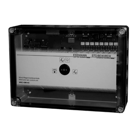
- Page 1 Wind-/Regenmeldezentrale WRZ 40M-4G Technische Information und Bedienungsanleitung Wind and rain detection system WRZ 40M-4G Technical information and operating instruction...
-
Page 2: Table Of Contents
Wind-/Regenmeldezentrale WRZ 40M-4G Inhalt Allgemeines und Sicherheit............................Produktbeschreibung..............................Funktion................................Besonderheiten............................Aufbau der Grundplatine und Anschlussmöglichkeiten................Musterverkabelungsplan............................Technische Daten..............................Montage................................... Montageablauf............................Elektrische Anschlüsse..............................Anschluss Netz 230 V AC..........................Anschluss Wind-/Regenmelder WRM/2 24V....................6.2.1 Anschluss Regenmelder RM/2 24V....................Direkter Anschluss der Antriebe 230 V und Lüftungstaster 24 V............. -
Page 3: Allgemeines Und Sicherheit
Wind-/Regenmeldezentrale WRZ 40M-4G Allgemeines und Sicherheit Dokumentation: Diese Dokumentation gilt ausschließlich der Installation sind die elektrischen und mechanischen für das Produkt oder die Produktserie gemäß der Typen- Komponenten auf einwandfreie Funktion zu prüfen und bezeichung des Deckblattes und muss im vollen Umfang die Prüfungen und ihre Ergebnisse zu dokumentieren. - Page 4 Wind-/Regenmeldezentrale WRZ 40M-4G Entsorgung: Verpackungen sind sachgerecht zu Leitungen für Kleinspannungen (z. B. 24 V DC) sind entsorgen. Die elektrischen Geräte sind an Sam- getrennt von Niederspannungsleitungen (z. B. 230 V AC) melstellen für die Rücknahme von Elektro- und Elektro- zu verlegen.
-
Page 5: Produktbeschreibung
Produktbeschreibung Funktion Die Wind-/Regenmeldezentrale WRZ 40M-4G ist eine Steuerzentrale zur Ansteuerung von max. 40 x 230 V AC Lüftungsantriebe (z. B. Typ M3) mit einer Gesamtstromaufnahme von maximal 8 A verteilt auf 4 Antriebsgruppen (max. 2 A pro Antriebsgruppe). Die Ansteuerung erfolgt über Wind-/Regenmelder 24 V, Regenmelder 24 V, Lüftungstaster 24 V, Schlüsseltaster 24 V oder Lüftungstaster 230 V. -
Page 6: Aufbau Der Grundplatine Und Anschlussmöglichkeiten
4 24 V 24 V Die WRZ 40M-4G Wind-/Regenmeldezentrale bietet Anschlussmöglichkeiten für: 1 x Lüftungstaster 24 V (z. B. Typ LTA 11) oder 1 x Schlüsseltaster 24 V (z. B. Typ LTA 12 oder LTA 13) 1 x Wahlschalter (optional) Max. -
Page 7: Musterverkabelungsplan
Zentral ZU, wirkt auf alle 4 Antriebsgruppen (Sperrung der Lüftungsfunktion) Wahlschalter integriert im Gehäuse- ZU: Alle Lüftungsaggregate fahren zu. Die manuelle Lüftung ist gesperrt. deckel der WRZ 40M-4G (optional) AUTOMATIK: automatisches Schließen aller Lüftungsaggregate bei einer Wind- oder Regenmeldung. ZU(I) AUTOMATIK(O) HAND(II) HAND: Lüftung AUF / ZU manuell über 24 V oder 230 V Lüftungstaster. -
Page 8: Technische Daten
-25 °C bis 75 °C Zulässige Luftfeuchtigkeit (Betrieb/Lagerung/Transport): 10 % bis 95 % Geeignet für Außenmontage: Nein Schutzart: IP 66 (Gehäuse) WRZ 40M-4G ohne Wahlschalter IP 54 (Gehäuse) WRZ 40M-4G mit Wahlschalter Zulassungen und Nachweise CE-konform: Gemäß EMV-Richtlinie 2014/30/EU und der Niederspannungsrichtlinie 2014/35/EU... -
Page 9: Montage
Wind-/Regenmeldezentrale WRZ 40M-4G Montage Hinweis: Die Sicherheitshinweise auf Seite 3 müssen beachtet werden. Befestigungsschrauben Für die Montage der WRZ 40M-4G Wind-/Regenmeldezentrale einen trockenen Raum auswählen. Für die Montage der Lüftungstaster gut sichtbare und erreichbare Orte aussuchen. 5.1 Montageablauf Grundplatine ► Zentrale öffnen und zuerst die Grundplatine mit Steuerelektronik aus dem Kunststoffgehäuse ausbauen. -
Page 10: Elektrische Anschlüsse
Wind-/Regenmeldezentrale WRZ 40M-4G Elektrische Anschlüsse Anschluss Netz 230 V AC Achtung! Vor Arbeiten an der Anlage ist die Netzspannung allpolig freizuschalten und gegen unbeabsichtigtes Widereinschalten zu sichern. Vorsicht! Unsachgemäßes Arbeiten an spannungsführenden Bauteilen kann zu einem Stromschlag führen! 12 13 14 15 Der elektrische Anschluss muss durch ausgewiesenes Elektrofachpersonal durchgeführt werden. -
Page 11: Anschluss Regenmelder Rm/2 24V
Wind-/Regenmeldezentrale WRZ 40M-4G 6.2.1 Anschluss Regenmelder RM/2 24V 2. RM/2 24V Klemmenbezeichnung DIP-Schalter Einstellung im RM/2 24V im RM/2 24V 1. RM/2 24V 2. RM/2 24V 1: Spannungsversorgung +24 V DC 2: Spannungsversorgung -24 V DC 3: Relaiskontakt (Arbeitskontakt) 4: Relaiskontakt (Schließer) WRZ 40M-4G 1. -
Page 12: Anschluss Antriebe 230 V, Lüftungstaster 230 V Und Schlüsseltaster
Wind-/Regenmeldezentrale WRZ 40M-4G 6.3.1 Anschluss Antriebe 230 V mit Lüftungstaster 230 V und Schlüsseltaster 24 V Schlüsseltaster 24 V Antriebs- Antriebs- Antriebs- Antriebs- gruppe 1 gruppe 2 gruppe 3 gruppe 4 ZU N AUF.PE ZU N AUF.PE ZU N AUF.PE ZU N AUF.PE... -
Page 13: Anschluss Potenzialfreier Kontakt
Wind-/Regenmeldezentrale WRZ 40M-4G Anschluss potenzialfreier Kontakte Potenzialfreie Kontakte zur Weiterleitung der Wind-/Regenmeldung Kontaktbelastung: 230 V / max. 2 A Anschluss Wahlschalter ZU (I) / AUTOMATIK (O) / HAND (II) Hinweis: Werden die Klemmen 16, 17 und 18 nicht verschaltet, so ist die Funktton "AUTOMATIK" aktiv. -
Page 14: Anschluss 4 X Wind-/Regenmeldezentralen (Master/Slave Betrieb), 1 X Schlüsselaster 24 V Und Dip-Schalter Einstellungen
1 x Schlüsseltaster 24 V und DIP-Schalter Einstellung Die WRZ 40M-4G bietet die Möglichkeit 3 weitere Zentralen durch eine Busleitung anzuschließen. Das ermöglicht einen Master/Slave Betrieb. Die Hauptzentrale ist der Master. Sie erteilt Befehle an alle weiteren Slave-Zentralen über eine Busleitung. -
Page 15: Und Dip-Schalter Einstellungen
1 x Lüftungstaster 24 V und DIP-Schalter Einstellung Die WRZ 40M-4G bietet die Möglichkeit 3 weitere Zentralen durch eine Busleitung anzuschließen. Das ermöglicht einen Master/Slave Betrieb. Die Hauptzentrale ist der Master. Sie erteilt Befehle an alle weiteren Slave-Zentralen über eine Busleitung. -
Page 16: Dip-Schalter Funktionen
Der Antriebsausgang (ZU oder AUF) wird nach Betätigung des Lüftungstasters für 3 Minuten mit Spannung versorgt. Danach spannungsfrei. Achtung: Die Antriebe müssen direkt, ohne 230 V Lüftungstaster, an den Klemmen der WRZ 40M-4G angeschlossen werden. 1 2 3 4 5 6 7 8 9 10 11 12 DIP-Schalter 2: Einstellung der Einschaltverzögerung Verzögerungszeit einer anstehenden Auslöse-Windgeschwindigkeit bis die Anlage die Lüftungsaggregate schließt. -
Page 17: Aktivierung Der Dip-Schalter Funktionen
Wind-/Regenmeldezentrale WRZ 40M-4G DIP-Schalter 9: Ansteuerung von Magnetventilen in Pneumatikanlagen Die Antriebsgruppen werden nach einem Zustandswechsel in Richtung AUF bzw. ZU impulsartig für die Dauer von 2 Sek. mit Spannung versorgt. 1 2 3 4 5 6 7 8 9 10 11 12... -
Page 18: Betriebsarten Des Wahlschalters (I, O, Ii)
Wind-/Regenmeldezentrale WRZ 40M-4G Betriebsarten des Wahlschalters (I, O, II) Die Wind-/Regenmeldezentrale bietet 3 Betriebsarten, die mittels optionalem Wahlschalter ausgewählt werden können. Ohne Wahlschalter ist der Automatikbetrieb eingestellt. AUTOMATIK-Betrieb (O) Angeschlossene Lüftungsaggregate können manuell zum Lüften über Lüftungstaster auf- und zugefahren werden. Bei hohen Windgeschwindigkeiten, Regen oder Schnee werden alle angeschlossenen Lüftungsaggregate automatisch... -
Page 19: Led-Anzeigen
Wind-/Regenmeldezentrale WRZ 40M-4G Test AUTOMATIK-Betrieb (O) am Windmelder LED Nr. 1 leuchtet GRÜN. ► Wahlschalter auf "AUTO" Betrieb stellen. LEDs Nr. 3 und Nr. 5 sind aus (Sensoren sind nicht ausgelöst). LEDs für angeschlossene Antriebsgruppen (CH1 bis CH4) leuchten ROT. -
Page 20: Störungshilfen
Wind-/Regenmeldezentrale WRZ 40M-4G Störungshilfen Problem Mögliche Ursachen Abhilfe Klappen fahren bei Regen/ • Defekte oder falsch angeschlossene • Anschlussleitungen kontrollieren ggf. Schneefall nicht zu Anschlussleitungen richtig anschließen • DIP-Schalter im Wind-/Regenmelder falsch • DIP-Schalter im Wind-/Regenmelder nach eingestellt Anleitung richtig einstellen (siehe Anschluss WRM/2, RM/2, Seite 10, 11) •... -
Page 21: Windstärken Nach Beaufort
Wind-/Regenmeldezentrale WRZ 40M-4G Windstärken nach Beaufort Windstärke Merkmal Geschwindigkeit km/h Staudruck nach Beaufort Pa=N/m² Stille 0 - 0,2 Unter 1 0 - 0,2 leiser Zug 0,3 - 1,5 1 - 5 0,06 - 1,4 leichte Brise 1,6 - 3,3 6 - 11... -
Page 22: Datei: Ti_Wrz_40M-4G_D_Gb.indd / Ausgabe 03 / 29.09.2016 / Art.nr
Wind and rain detection system WRZ 40M-4G Content Page General information and safety instructions......................Product description............................... Function................................Special features............................Structure of the circuit board and connection options................Model cable plan..............................Technical data............................... Installation..................................Installation process..........................Electrical connection..............................Connection mains 230 V AC......................... -
Page 23: General Information And Safety Instructions
Wind and rain detection system WRZ 40M-4G General information and safety instructions Operation: Safe operation is guaranteed if the accepta- Documentation: This documentation is exclusively valid ble rated values and guidelines regarding maintenance for the product or product range as stated in the type de-... - Page 24 Wind and rain detection system WRZ 40M-4G Before work is carried out on the system, the Disposal: Packaging is to be disposed of mains current and emergency power supply (eg. appropriately. Electrical equipment is to be dispo- rechargeable batteries) is to be disconnected from all- sed of at recycling collection points for scrap electrical poles and secured to prevent accidental switch-on.
-
Page 25: Product Description
Product description Function The wind and rain detection system WRZ 40M-4G is a control panel for triggering of max. 40 x 230 V AC ventilation drives (for example, type M3) with a total power consumption of no more than 8 A distributed on 4 driving groups (max. 2 A per driving group). -
Page 26: Structure Of The Circuit Board And Connection Options
24 V 24 V The WRZ 40M-4G wind / rain control unit provides connections for: 1 x vent switch 24 V (e.g. type LTA 11) or 1 x key switch 24 V (e.g. type LTA 12 or LTA 13) 1 x selector switch (optional) Max. -
Page 27: Model Cable Plan
Wind and rain detection system WRZ 40M-4G Model cable plan Up to 200 m J-Y(ST)Y 2 x 2 x 0,8mm² Up to 350 m J-Y(ST)Y 4 x 2 x 0,8mm² Up to 350 m J-Y(ST)Y 4 x 2 x 0,8mm²... -
Page 28: Technical Data
Permitted humidity (operation / storage / transport): 10 % to 95 % Suitable for external mounting: Protection rating: IP 66 (housing) WRZ 40M-4G without selector switch IP 54 (housing) WRZ 40M-4G with selector switch Authorisations and certifications CE compliant: According to EMV Directive 2014/30/EU and the... -
Page 29: Installation
Wind and rain detection system WRZ 40M-4G Installation Note: The safety instructions on page 23 must be observed. Fixing screws Install the wind-/rain-control unit WRZ 40M-4G in a dry environment. Install the vent switches in a position which can be easily seen and accessed. -
Page 30: Electrical Connection
Wind and rain detection system WRZ 40M-4G Electrical connection Connection mains 230 V AC Attention! Before working on the installation, the mains voltage is all poles unlock and secure it against inadvertent power-cons. 12 13 14 15 Caution! From incorrect work on live electrical components can lead to electric shock! The electrical connection must be performed by qualified electricians. -
Page 31: Connection Rain Detector Rm/2 24V
Wind and rain detection system WRZ 40M-4G 6.2.1 Connection rain detector RM/2 24V 2. RM/2 24V Terminal designation DIP switch setting in the RM/2 24V in the RM/2 24V 2. RM/2 24V 1. RM/2 24V Powersupply +24 V DC Powersupply -24 V DC... - Page 32 Wind and rain detection system WRZ 40M-4G 6.3.1 Connection drives 230 V with vent switch 230V and key switch 24V Key switch 24 V Driving group 1 Driving group 2 Driving group 4 Driving group 3 CLOSE, N, OPEN, PE...
-
Page 33: Connection Potential-Free Contacts
Wind and rain detection system WRZ 40M-4G Connection potential-free contacts Potential-free contacts for transmitting the wind/rain signal Contact rating: 230 V / max. 2 A Connection selector switch CLOSE (I) / AUTOMATIC (O) / HAND (II) Note: If the terminals 16, 17 and 18 are not connected, the function "AUTOMATIC" is active. -
Page 34: Dip Switch Settings
1 x key switch 24 V and DIP switch settings The WRZ 40M-4G offers the possibility of connecting three further control units through a bus line. This allows a master /slave operation. The main control unit is the master. The main control unit issued orders to all other slave control units via a bus line. -
Page 35: Connection 4 X Wind/Rain Control Units (Master/Slave Operation), 1 X Vent Switch 24 V And Dip Switch Settings
1 x vent switch 24 V and DIP switch settings The WRZ 40M-4G offers the possibility of connecting three further control units through a bus line. This allows a master /slave operation. The main control unit is the master. The main control unit issued orders to all other slave control units via a bus line. -
Page 36: Dip Switch Settings
Wind and rain detection system WRZ 40M-4G DIP-switch settings Combinations of various DIP-switch settings are possible, e.g. DIP-switch 3 = ON and 4 = ON. Factory settings for the DIP-switch are position OFF. Position ON means: 1 2 3 4 5 6 7 8 9 101112 DIP-switch 1: Ventilation via vent switch 24 V With connected 24 V vent switch all drive groups can be driven at the same time OPEN or CLOSED. -
Page 37: Activating The Dip Switch Functions
Wind and rain detection system WRZ 40M-4G DIP-switch 9: Control of solenoid valves in pneumatic systems Motor groups are supplied with power in pulses for a period of 2 sec. after a change of status in direction OPEN or CLOSED... -
Page 38: Operating Modes Of The Selector Switch (I, O, Ii)
Wind and rain detection system WRZ 40M-4G Operating modes of the selector switch (I, O, II) The wind and rain detection system offers 3 operating modes that can be selected by optional selector switch. If the selector switch is not used, the automatic mode is set. -
Page 39: Led Displays
Wind and rain detection system WRZ 40M-4G Test AUTOMATIC mode (O) on the wind detector LED no. 1 lights GREEN. ► Set selector switch to "AUTOMATIC" mode (O). LEDs no. 3 and no. 5 are off (sensors are not triggered). -
Page 40: Troubleshooting
Wind and rain detection system WRZ 40M-4G Troubleshooting Problem Possible causes Help Vents do not close in case of • Defects or incorrectly connected cables • Check the connection cables for correct rain / snow connection • DIP switch in wind-/rain detector set •... -
Page 41: Beaufort Wind Scale
Wind and rain detection system WRZ 40M-4G Beaufort wind scale Beaufort Descrpition Speed km/h Dynamic pressure wind scale Pa=N/m² Clam 0 - 0,2 Unter 1 0 - 0,2 Light air 0,3 - 1,5 1 - 5 0,06 - 1,4 Light breeze...
Need help?
Do you have a question about the WRZ 40M-4G and is the answer not in the manual?
Questions and answers