
Summary of Contents for STAMPFL JUNIOR 1D
- Page 1 V. 1 29.08.2017 ASSEMBLY GUIDE JUNIOR 1D SHORTWAVE RECEIVER KIT DOPPELSUPER, 10.7 MHZ-455 KHZ AM/SSB 1.5 - 30 MHZ HAM ELECTRONICS...
-
Page 2: Table Of Contents
P 15 WIRES ON BACK P 31 PUSHBUTTONS P 16 PRESELECTOR BUTTON P 32 DISPLAY ASSEMBLY P 17 JUNIOR 1D BLOCK DIAGRAM P 33 TOROIDS P 18 JUNIOR 1D INPUT CIRCUITS P 34 POTENTIOMETERS (POTI) P 19-20 JUNIOR 1D HF PART... - Page 3 JUNIOR 1D An LM380 in conjunction with a 4Ohm loudspeaker guarantees Again and again I had requests from Junior1 builders, a strong audio reproduction. whether digital frequency displays or reception areas can be The operation of J1D is reduced to the essentials.
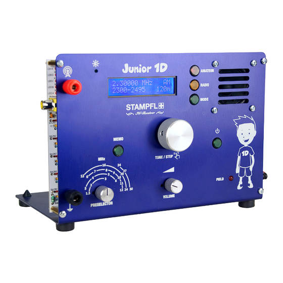
- Page 4 TECHNICAL SPECIFICATIONS As with any other electronic circuit, the development of • reception area: 1,5-30MHz Junior 1D was the greatest challenge to find the best possible • Modulation types: AM-DSB compromise. At a Product of this type should also have its •...
- Page 5 RESISTORS: 1 We first fit the flat components: We start with the Resistors which we check for its right value before soldering it to the Print Metal Film Resistors: Color Code: brown black | black | brown brown Metal Film Resistors: 100k Color Code: | black | black |...
- Page 6 RESISTORS: 2 We first fit the flat components: We start with the Resistors which we check for its right value before soldering it to the PCB Metal Film Resistors: Color Code: | black | brown Metal Film Resistors: Color Code: blue | black | gold...
- Page 7 RESISTORS: 3 We first fit the flat components: We start with the Resistors which we check for its right value before soldering it to the PCB Metal Film Resistors: 2,7R Color Code: violet | black | silver brown Alignment does not matter. Carbon Film Resistors: 470R Color Code:...
- Page 8 RESISTORS: 4 CORRECTION!: Instead of the 390R 220R Resistors is soldered in. Carbon Film Resistors: gold Color Code: yellow violet green Alignment does not matter. Carbon Film Resistors: Color Code: gold violet Alignment does not matter. Carbon Film Resistors: 220R Color Code: gold brown...
- Page 9 DIODES: 5 ATTENTION!: Keep mounting direction in mind! Switch diode Typ: BA282...
- Page 10 DIODES: 6 ATTENTION!: Keep mounting direction in mind! Z-Diode Type: V8V2 LED: The shorter leg is the minus pole (C).
-
Page 11: Blocking Capacitors: 7
BLOCKING CAPACITORS: 7 ATTENTION!: The design of the 4,7nF ist the same as the 0,1uF! Blocking Capacitors: 0,1uF Ceramic capacitor: 4,7nF Alignment does not matter. Alignment does not matter. In excess available! -
Page 12: Inductors: 8
INDUCTORS: 8 ATTENTION!: Spool body could break! Bend wires with care. Inductors: 680uH Color Code: blue grau brown silver Alignment does not matter. Inductors: 270uH Color Code: violet brown silver Alignment does not matter. Inductors: 33uH Color Code: orange orange | black | silver Alignment does not matter. -
Page 13: Ceramic Capacitors
CERAMIC CAPACITOR: 9 Ceramic Capacitor: 68pf Alignment does not matter. Ceramic Capacitor: 270pf Alignment does not matter. Ceramic Capacitor: 330pf Alignment does not matter. Ceramic Capacitor: 4,7pf Alignment does not matter. At the voltage regulator 7805 we bend the 3 feet at a 90 90°... - Page 14 IC SOCKET: 10 CHECK MARKINGS ON PRINT! Socket and markings on Print have to match. Make sure no short circuits are made. Sockel: 40Pol Keep mounting direction in mind! Sockel: 16Pol Keep mounting direction in mind! Sockel: 8Pol Keep mounting direction in mind!
- Page 15 IC: 11 NE612 ATTENTION!: Verify IC Typ and direction! LM380 ATTENTION!: Verify IC Typ and direction! ATMEGA644 ATTENTION!: Verify IC Typ and direction! Bend IC legs slightly towards the inside. A4100D wird direkt in die Platine gelötet. ATTENTION!: Verify IC Typ and direction! Bend IC legs slightly towards the inside.
-
Page 16: Miscellaneousp
MISCELLANEOUS: 12 XO 10,245MHz Is soldered directly to the board. ATTENTION!: Verify IC Typ and direction! 20 MHz Quarz Alignment does not matter. 16-pin connector strip (LCD) 10 Speed 10K Potentiometers It is used later for the contrasts adjustment of the LCD display. Headphone jack... - Page 17 MISCELLANEOUS: 13 Filter: 33-455HT LT455HTW Switch-on Relais: 12ND05 Cinch antenna socket Ceramic filter: 10,7MHz-(Optional: 8-pin quartz filter: 10MXF12D by „Funkamateur“ or MXF 10.7 - 7.5C) Alignment does not matter. Ceramic resonator Alignment does not matter.
-
Page 18: Electrolytic Capacitors: 14
ELECTROLYTIC CAPACITORS: 14 Electrolytic Capacitors: ATTENTION!: Observe polarity! The longer wire is the positive pole. Electrolytic Capacitors: 22uF ATTENTION!: Observe polarity! The longer wire is the positive pole. Electrolytic Capacitors: 220uF ATTENTION!: Observe polarity! The longer wire is the positive pole. Power jack Reverse polarity protection diode: RL4A... -
Page 19: Dds Module: 15
DDS MODULE: 15 Transitors: BC547 Keep mounting direction in mind! Capacity diodes: BB112 Keep mounting direction in mind! Fet: J310 Keep mounting direction in mind! DDS Module Keep mounting direction in mind! Rotary encoder Extender... -
Page 20: Pushbuttons: 16
PUSHBUTTONS: 16 Button red with Socket Keep mounting direction in mind! (Indentation pointing south) see detail photo Button green with Socket Keep mounting direction in mind! (Indentation pointing south) see detail photo Spacers: M3x12 Screws: M3x5 Button yellow with Socket Keep mounting direction in mind! (Indentation pointing south) see detail photo... -
Page 21: Display Assembly: 17
DISPLAY ASSEMBLY: 17 Pin strip (short contacts) Solder at the top of the Display. Insert the Display on the socket strip (see point 12). Bolt on Display with M3x5 Screws. Mount spacer with: M3x20. Fix spacer with: M3x5. - Page 22 TOROIDES: 18 METHOD!: Wrap the wire on toroid, shorten it and pre-tin the ends. The wire can be tinned directly at a temperature of 350 ° c. CU Wire 0.5mm 2m/79in length Toroid: Wire length: 30cm/12in Windings: 9 (First thread is considered a winding) Toroid: Wire length: 50cm/20in...
-
Page 23: Potentiometers (Poti) P
POTENTIOMETERS TYPE A: 19 NOTE!: Kit is delivered partly with TYP A. Type B is always included. Poti: Volume Preselector Pay attention to vertical installation! Advantage: Quick installation. Disadvantage: Can lead to cold soldering joints in Partly included prolonged use. POTENTIOMETERS TYPE B: Poti: Lautstärke... - Page 24 POTENTIOMETERS TYPE B: 20 Cable length: 6x70mm/2.75inc Poti: Preselector Poti: Volume LED: 5mm Signal strength level: Weak continuous lighting at DSB is normal The longer wire is the positive pole. Cable: 2x80mm/3.14inc...
-
Page 25: Back: 21
BACK: 21 Turn PCB 180° Fuse holder & Fuse Cinch Connector: (10,7MHz IF Output) for MR. PAN Pin strip: 2Pol Jumper free: With headphones (STEREO only) Jumper short: With external speakers... -
Page 26: Power Check: 22
POWER CHECK: 22 Positive (internal contact red) Loudspeaker: Connect to board. 2x40mm flex Battery Pack: Solder the connector Positive (internal contact red). ON / OFF control The receiver makes a click sound when switching on. All buttons as well as the display must light up. -
Page 27: P 1-4 Adjust The Display Contrast
ADJUST DISPLAY CONTRAST: 23 Contrast increases clockwise Adjust the display contrast via the 10-speed potentiometer. When the memory is empty, the display shows only MHZ - 65535Hz STEP... -
Page 28: System Check: 24
SYSTEM CHECK: 24 Check the AMATEUR button Repeatedly pressing the button will show all HAM radio bands. Check the RADIO button Repeatedly pressing the RADIO button will show all radio bands. Check the MODE button Repeatedly pressing the button will change the modulation modes: Am, DSB Check the rotary encoder Repeatedly pressing the button will show all Frequency steps. - Page 29 EMPFANGSCHECK: 25 Check the volume control Volume of the noise increases clockwise. Check the headphone connection Connect STEREO headphones to headphone jack. Remove jumper from pin strip. See page 21. Reception test Temporary connecting an antenna to the receiver. Either via antenna connection 50 Ohm or directly with residual wire at the HZ input. Check of the 5-stage preselector 1.5-3MHz tune Preselector controller to maximum field strength.
-
Page 30: P 8 Speaker Assembly
SPEAKER ASSEMBLY: 26 Loudspeaker Connection contacts point downwards! Screw: M3x12 Nut: Rubber Feed... -
Page 31: P 9 Bushing Assembly
BUSHING ASSEMBLY: 27 Antenna socket Wire length 90mm / 3.5inc Ground socket Wire length 60mm / 2.35inc... -
Page 32: Pcb Mounting: 28
PCB MOUNTING: 28 Assembly: LED, Preselector, Volume is clamped into the bore. Connect the wire to the grounding GND. -
Page 33: Pcb Centering: 29
PCB CENTERING: 29 Tighten the screws only loosely. Tighten the screw loosely. Then tighten the screws. Then tighten screws. finish it with tighten the screws. Thread Antenna wire and grounding wire through solder eyes. -
Page 34: P 14 Battery Pack Assembly
BATTERY PACK ASSEMBLY: 30 Nylon screw M3 Nut:... -
Page 35: P 15 Wires On Back
WIRES ON BACK: 31 Solder the wire to the HY Z input. Solder the wire to the grounding GND. Solder the wires to the loudspeaker output. - Page 36 ALIGN THE PRESELECTOR KNOB: 32 turn receiver on Select the reception frequency 7.0 MHz. Connect the device to the antenna. Set the Preselector to the maximum reception field strength. Press the knob on the stem to show the direction 7 MHz.
- Page 37 JUNIOR 1D BLOCK SCHEMATIC: 33...
-
Page 38: P 18 Junior 1D Input Circuits
JUNIOR 1D INPUT CIRCUITS: 34... -
Page 39: Junior 1D Hf Part: 35
JUNIOR 1D HF PART: 35... - Page 40 JUNIOR 1D DDS VFO: 36...
- Page 41 JUNIOR 1D ON/OFF CIRCUIT: 37...
Need help?
Do you have a question about the JUNIOR 1D and is the answer not in the manual?
Questions and answers