Subscribe to Our Youtube Channel
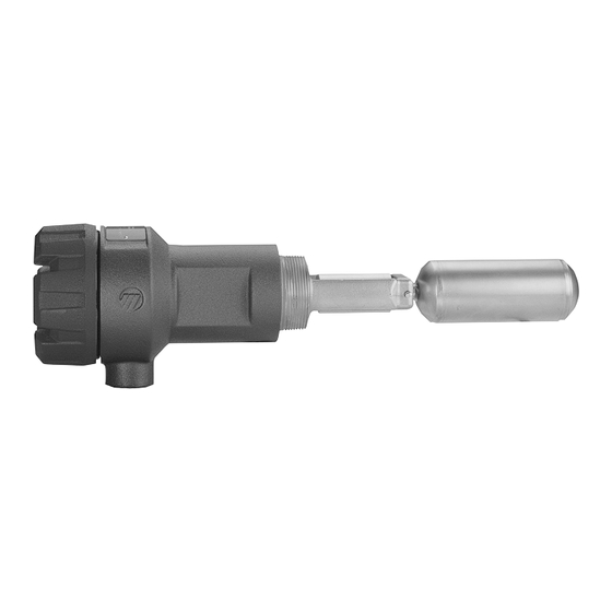
Summary of Contents for Magnetrol Tuffy T31
- Page 1 Tuffy Liquid Level Controls ® with Electric Switches nstallation and Operating Manual Side Mounted Float Level Switch...
- Page 2 - tag n° ton/crates against the packing slip and report any discrep- ancies to Magnetrol. Check the nameplate model number to be sure it agrees with the packing slip and purchase order. Check and record the serial number for future refer- ence when ordering parts.
- Page 3 WIRING CAUTION: power must be switched OFF before wiring the unit. Internal ground wire External ground wire use min. 14 AWG wire Terminal connections Terminal connections DPDT dry contact switch SPDT dry contact switch with silver contacts with silver or gold contacts Terminal connections Terminal connections DPDT dry contact switch...
-
Page 4: Troubleshooting
CALIBRATION For T31-T35 / T3B units Properly selected TUFFY units do not need any field calibration. For T3C: field adjustable differential units The Adjustable Differential Tuffy II, model T3C, may be set in the field for one of a variety of level differentials. By specific place- ment of the stops in the holes of the adjustment plate, the level differential may be changed. -
Page 5: Preventive Maintenance
PREVENTIVE MAINTENANCE Periodic inspections are a necessary means to keep your level control in good working order. This control is a safety device that protects the valuable equipment it serves. A systematic program of preventive maintenance should be implemented when the control is placed into service. -
Page 6: Replacement Parts
REPLACEMENT PARTS Partn°: Serial n°: See nameplate, always provide complete partn° and Digit in partn°: 8 9 10 serial n° when ordering spares. X = product with a specific customer requirement E X P E D I T E S H I P P L N ( E S P ) Several parts are available for quick shipment, within max. -
Page 7: Dimensions In Mm (Inches)
DIMENSIONS in mm (inches) T31 and T35: threaded narrow differential T31: 220 (8.66) T35: 200 (7.86) (8.29) (3.29) T31: 91 (3.59) T35: 85 (3.35) (4.39) 2" NPT Cable entry T31, T33 and T35: flanged narrow differential T31: 221 (8.72) T33: 190 (7.50) (8.29) T35: 201 (7.92) (3.35) - Page 8 DIMENSIONS in mm (inches) T3B: interface (17.62) (8.23) (3.35) (4.39) (6.78) Cable entry...
-
Page 9: Model Identification
MODEL IDENTIFICATION T 3 1 Tuffy with 316/316L (1.4401/1.4404) float - min S.G. 0,4 / max 49,6 bar (720 psi) T 3 2 Tuffy with 316/316L (1.4401/1.4404) float - min S.G. 0,6 / max 149 bar (2160 psi) T 3 3 Tuffy with Hastelloy C (2.4819) float - min S.G. - Page 10 MODEL IDENTIFICATION SEE PAGE 9 DESIGN CODE AND FLANGE MATERIAL Design codes ASME Flange material Model Standard ASME B31.3 NACE B31.3 & NACE – – Carbon steel Carbon steel w. 316/316L cladding T31/T32/T35 316/316L stainless steel T3B/T3C Carbon steel w. Hastelloy C cladding Hastelloy C (2.4819) SWITCH TYPE (see table below - "SWITCH MECHANISMS") SPDT with silver contacts...
- Page 11 ALLOWABLE OPERATING RANGE Switch with silver contacts A, B A: cast iron housing B: cast aluminium housing Process Temperature (°C) ALLOWABLE OPERATING RANGE Switch with gold plated contacts A, B A: cast iron housing B: cast aluminium housing Process Temperature (°C)
- Page 12 ALLOWABLE OPERATING RANGE Hermetically sealed switch with silver or gold plated contacts A, B A: cast iron housing B: cast aluminium housing Process Temperature (°C) OPTIONAL MOUNTING FLANGES for 2" NPT threaded TUFFY models Raised face mounting flanges are available in the sizes and materials shown below. Consult factory (C/F) for additional flange sizes.
- Page 13 EXTERNAL CAGES FOR NARROW DIFFERENTIAL TUFFY (T31, T35) DIMENSIONS in mm (inches) CAGE – STYLE Sealed cage 033 Flanged cage 035 4" ASME Tuffy flange 4" ASME Slip-on chamber flange ® (4.50) (4.50) (5.91) (7.09) (7.36) (7.36) CAGE – PROCESS CONNECTION Threaded/Socket weld DIMENSION A CONNECTION...
- Page 14 BASIC MODEL NUMBER 0 3 3 4" sealed cage (matches TUFFY with 2" NPT-M process connection) ® 0 3 5 4" flanged cage (matches TUFFY with 4" ASME flange process connection) ® MATERIAL OF CONSTRUCTION Carbon steel 316/316L (1.4401/1.4404) stainless steel PROCESS CONNECTION –...
- Page 15 Notes...
-
Page 16: Service Policy
SERVICE POLICY Owners of Magnetrol products may request the return of a control; or, any part of a control for complete rebuilding or replacement. They will be rebuilt or replaced promptly. Magnetrol International will repair or replace the control, at no cost to the purchaser, (or owner) other than transportation cost if: a.


Need help?
Do you have a question about the Tuffy T31 and is the answer not in the manual?
Questions and answers