Table of Contents
Advertisement
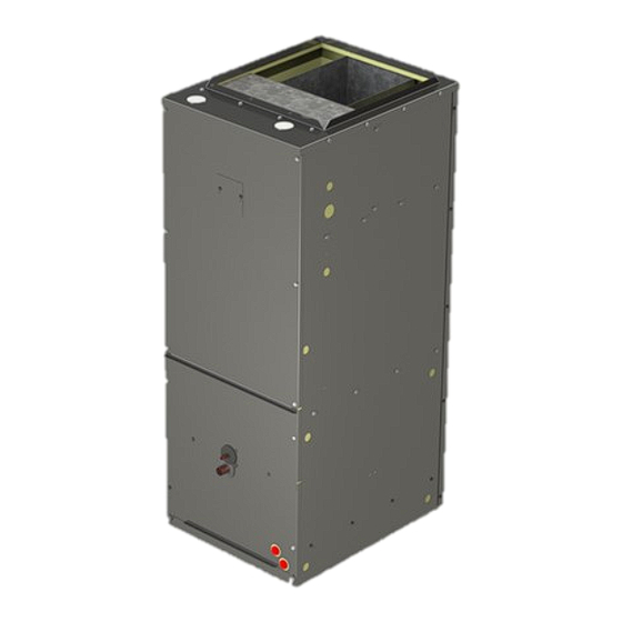
DUC Series Vertical FCU
Installation, Operation and Maintenance
Manual
VERTICAL
OPTION
HORIZONTAL
OPTION
Magic Aire DUC Series vertical fan coil units are direct drive High Efficiency air handlers delivering nominal
airflows of 600 to 2000 CFM and nominal cooling capacities of 1-1/2 to 5 tons.
Units may be specified with chilled water or DX cooling coils and hot water or electric heating coils to meet space
cooling loads or heating loads or both.
035-000050-001
1
DUC IOM 1.2 5-9-2018
Advertisement
Table of Contents

Related Manuals for Magic Aire DUC Series


Summary of Contents for Magic Aire DUC Series
- Page 1 HORIZONTAL OPTION Magic Aire DUC Series vertical fan coil units are direct drive High Efficiency air handlers delivering nominal airflows of 600 to 2000 CFM and nominal cooling capacities of 1-1/2 to 5 tons. Units may be specified with chilled water or DX cooling coils and hot water or electric heating coils to meet space cooling loads or heating loads or both.
- Page 2 THIS PAGE INTENTIONALLY LEFT BLANK 035-000050-001 DUC IOM 1.2 5-9-2018...
-
Page 3: Table Of Contents
DUC Series Vertical FCU Installation, Operation and Maintenance Manual Installation, Start-Up and Service Instructions Page Topic SAFETY CONSIDERATIONS PRODUCT NOMENCLATURE ACCESSORIES INSTALLATION Pre-installation Rigging Service Clearances Return Air & Unit Orientation Unit Suspension or Floor Mount Unpacking Condensate Drain Ductwork... - Page 4 THIS PAGE INTENTIONALLY LEFT BLANK 035-000050-001 DUC IOM 1.2 5-9-2018...
- Page 5 Installation and maintenance are to be performed only This manual gives instructions regarding installation, by qualified personnel who are familiar with local codes operation and maintenance for the DUC Series fan coil and regulations and are experienced with HVAC equip- unit. For more information refer to: ment of this type.
-
Page 6: Product Nomenclature
PRODUCT NOMENCLATURE—ACCESSSORIES MODEL NOMENCLATURE 9 10 11 12 13 14 Position D U C 1 2 B 2 B S 5 B B A M Example Label Direct Drive Drain Pan and Insulation Galvanized, Stainless Steel, Use our New Magic 4 Selection Generation Universal Software for:... - Page 7 PRODUCT NOMENCLATURE—ACCESSSORIES 035-000050-001 DUC IOM 1.2 5-9-2018...
-
Page 8: Installation
Do not store unit on vibrating surface. Magic Aire holds that this practice represents the stand- Damage to stationary bearings can occur. Set ard for professional installation whether or not this code unit off ground if in heavy rain area. - Page 9 INSTALLATION—SERVICE CLEARANCES CLEARANCE DIMENSION (INCHES) UNIT SIZE 06/08 36.0 36.0 36.0 22.0 6.0 9.0 10/12 36.0 36.0 36.0 25.0 6.0 10.0 14/16 36.0 36.0 36.0 27.0 6.0 11.0 36.0 36.0 36.0 31.0 6.0 11.0 06/08 12.0 7.0 19.4 35.7 45.0 10/12 12.0 7.0 23.5 40.6 50.0 14/16...
- Page 10 Cabinet and Drain Pan Configurations Notes: Return Air Cabinet is model digit 12; drain pan is digit 13. Refer to New Magic 4 software for selections and perfor- mance. All drain pans have front condensate drain connections (primary and auxiliary), and so are RH or LH, not both. 035-000050-001 DUC IOM 1.2 5-9-2018...
- Page 11 INSTALLATION—Configuration Conversion Vertical Only to Vertical/Horizontal Right Configura- Parts required: tion Part Number Description 076-002644-000 DRAIN PAN ASSY RH DRAIN MVA24 Note: This is a reference for a single type of conver- 076-002851-000 DRAINPAN SUPPORT MVA18/24 sion. Contact factory for instructions regarding your 016-000269-000 INSL DRAIN PAN DUC06/08 DB configuration change...
- Page 12 ISOMETRIC VIEW Figure 3a CEILING SUSPENSION DETAILS RIGHT HAND VIEW NOTE: 1. RIGHT HORIZONTAL AIRFLOW CONFIGURATION SHOWN. SIMILAR FOR LEFT HORIZONTAL CONFIGU- RATION. FRONT VIEW ITEM NO. DESCRIPTION QTY. DUC AIR HANDLER UNISTRUT, 1-5/8 X 1-5/8, 16 GA MIN, 9/16" DIA HOLES OR EQUIV ALL THREAD 3/8"...
-
Page 13: Service Clearances
INSTALLATION Unpacking supplied and installed. 1. Remove all packaging and any foreign material from unit. Pipe to condensate drain using PVC or copper or 2. Check blower wheel for free rotation. other suitable material. Pitch drain piping downward 3. Check copper lines, coil etc. for internal or hidden at a minimum slope of 1/8 inch per foot. -
Page 14: Refrigerant Piping
INSTALLATION Refrigerant Piping Chilled Water and Hot Water Coil Piping — Size Refrigerant coils have liquid and suction line connec- chilled water and hot water piping to deliver desired tions through the front of the cabinet. pressure drop and flow rate. Install control valves as required to allow temperature control system to control CAUTION: Use proper care when brazing including the water flow. -
Page 15: Electric Heater Accessory
INSTALLATION—ELECTRIC HEAT Electric Heater Accessory DANGER The electric heater may be factory-installed or field- installed. See Figures 5 through 8. WARNING: Hazardous voltage. Only qualified per- sonnel must install the electrical service. Disconnect Removal Procedure: and Lock Out all incoming power sources before con- 1. - Page 16 INSTALLATION—ELECTRIC HEAT Install Procedure: 7. Connect field wiring to the breaker-style power To install the electric heater, switches front heater.——-- WARNING! Be sure to provide the appropriate 1. Disconnect and lock out electrical power from the wire size and branch circuit protection as re- unit.
- Page 17 INSTALLATION—ELECTRIC HEAT Electric Heater Accessory-DUC size 06 and 08 DANGER The electric heater must be adjusted to fit unit sizes 1 WARNING: Hazardous voltage. Only qualified per- -ton, 1.5-ton and 2-ton unit models, See Figures 9a sonnel must install the electrical service. Disconnect through 9d.
-
Page 18: Electrical
INSTALLATION—ELECTRICAL DANGER DANGER NEVER enter an enclosed fan cabinet or reach into a WARNING: Hazardous voltage. Only qualified per- unit while the fan is running. sonnel must install the electrical service. Disconnect and Lock Out all incoming power sources before con- LOCK OPEN AND TAG the fan motor power discon- necting to electrical service. - Page 19 INSTALLATION—ELECTRICAL wiring must conform to the Class II temperature limita- DANGER tions described in the NEC. WARNING: Hazardous voltage. Only qualified per- Refer to factory wiring diagrams installed in the unit. sonnel must install the electrical service. Disconnect and Lock Out all incoming power sources before con- Use the MCA and MOPD from the nameplate or electric necting to electrical service.
-
Page 20: Wiring Diagrams
INSTALLATION—WIRING DIAGRAMS TYPICAL WIRING DIAGRAMS 115V, and 208/240V TYPICAL WIRING DIAGRAM - 115V TYPICAL WIRING DIAGRAM - 208/240V 035-000050-001 DUC IOM 1.2 5-9-2018... - Page 21 INSTALLATION—WIRING DIAGRAMS TYPICAL WIRING DIAGRAM Electric Heat: 1-6kW and 8-9.5kW TYPICAL WIRING—ELECTRIC HEAT TYPICAL WIRING—ELECTRIC HEAT 035-000050-001 DUC IOM 1.2 5-9-2018...
- Page 22 INSTALLATION—WIRING DIAGRAMS TYPICAL WIRING DIAGRAM Electric Heat: 14.5kW and 19.5kW TYPICAL WIRING—ELECTRIC HEAT TYPICAL WIRING—ELECTRIC HEAT 035-000050-001 DUC IOM 1.2 5-9-2018...
-
Page 23: Start-Up
START-UP Pre-Startup Building Envelope—All building windows and doors should be installed and closed before starting unit. Dur- ing summer construction, avoid unit sweating by allow- ing for gradual pull down: use reduced capacity and use maximum available airflow. Temperature Controls-Check that unit is connected to the controls system and communicating properly. -
Page 24: Service
SERVICE General DANGER 1. Review Safety Considerations at beginning of these NEVER enter an enclosed fan cabinet or reach into a instructions. Good safety habits are important tools when performing service procedures. unit while the fan is running. 2. To make speed measurements, use a laser-style LOCK OPEN AND TAG the fan motor power disconnect tachometer. - Page 25 DANGER NEVER enter an enclosed fan cabinet or reach into a unit while the fan is running. LOCK OPEN AND TAG the fan motor power disconnect switch before working on a fan. Take fuses with you and note removal on tag. Electric shock can cause personal injury or death.
-
Page 26: Filters
SERVICE—Filters Filters Access Panels FILTER SECTIONS — Open or remove filter panel to The 3 sections of the unit can be reached using the front access panels, removable using 5/16” socket or driver replace old filter with a new filter. See physical data ta- bles for filter data. - Page 27 SERVICE-Coil Removal and Reinstallation Procedure 5. Slide coil & drain pan assembly out of the unit (Fig 1. Perform procedure on the ground for safety. working at heights USE EXTREME CAUTION ob- 21). serve all FALL SAFETY considerations. Under all 6.
- Page 28 AIRFLOW PERFORMANCE - ECM-VE MOTOR Notes: 1. Data at sea level with 1” trow-away filter and dry coil. 2. Operating in area highlighted in gray not recom- mended 035-000050-001 DUC IOM 1.2 5-9-2018...
- Page 29 AIRFLOW PERFORMANCE - ECM-VE MOTOR Notes: 1. Data at sea level with 1” trow-away filter and dry coil. 2. Operating in area highlighted in gray not recom- mended 035-000050-001 DUC IOM 1.2 5-9-2018...
- Page 30 AIRFLOW PERFORMANCE - ECM-VE MOTOR Notes: 1. Data at sea level with 1” throw-away filter and dry coil. 2. Operating in area highlighted in gray not recom- mended 035-000050-001 DUC IOM 1.2 5-9-2018...
- Page 31 AIRFLOW PERFORMANCE - ECM-VE MOTOR Notes: 1. Data at sea level with 1” throw-away filter and dry coil. 2. Operating in area highlighted in gray not recom- mended 035-000050-001 DUC IOM 1.2 5-9-2018...
- Page 32 AIRFLOW PERFORMANCE - ECM-VE MOTOR Notes: 1. Data at sea level with 1” throw-away filter and dry coil. 2. Operating in area highlighted in gray not recom- mended 035-000050-001 DUC IOM 1.2 5-9-2018...
- Page 33 AIRFLOW PERFORMANCE - ECM-VE MOTOR Notes: 1. Data at sea level with 1” throw-away filter and dry coil. 2. Operating in area highlighted in gray not recom- mended 035-000050-001 DUC IOM 1.2 5-9-2018...
- Page 34 AIRFLOW PERFORMANCE - ECM-VE MOTOR Notes: 1. Data at sea level with 1” throw-away filter and dry coil. 2. Operating in area highlighted in gray not recom- mended 035-000050-001 DUC IOM 1.2 5-9-2018...
-
Page 35: Electrical Ratings
UNIT ELECTRICAL RATINGS ECM-VE Motor 120V ECM-VE Motor 208-240V/1 PH Notes: Minimum Wire Gauge is based upon Circuit 1 ampacity and the use of 75C wire at the unit. 15 and 20 KW Heating units require two supply circuits. 035-000050-001 DUC IOM 1.2 5-9-2018... -
Page 36: Electrical Ratings
UNIT ELECTRICAL RATINGS ECM-VE Motor 277V TOTAL MOTOR MINIMUM CIRCUIT Maxim um Overcurrent ELECTRIC HT ELECTRIC HEAT AMPS UNIT FLA MIN WIRE AMPACITY Protective Device (A) (KW) SIZE AWG* Size CIRCUIT 1 CIRCUIT 1 CIRCUIT 1 CIRCUIT 1 Voltage 277V 277V 277V 277V... -
Page 37: Dimensions
UNIT DIMENSIONS 035-000050-001 DUC IOM 1.2 5-9-2018... - Page 38 UNIT DIMENSIONS 035-000050-001 DUC IOM 1.2 5-9-2018...
- Page 39 UNIT DIMENSIONS 035-000050-001 DUC IOM 1.2 5-9-2018...
-
Page 40: Replacement Parts
REPLACEMENT PARTS 035-000050-001 DUC IOM 1.2 5-9-2018... - Page 41 REPLACEMENT PARTS 035-000050-001 DUC IOM 1.2 5-9-2018...
- Page 42 REPLACEMENT PARTS—CONTROL ASSEMBLY ECM, CHW and DX, EH ECM, CHW and DX PSC, CHW with Choke PSC, DX ECM, CHW and DX 035-000050-001 DUC IOM 1.2 5-9-2018...
- Page 43 REPLACEMENT PARTS *contact the factory or use the RPL system for replace- ment part information, lead time, and pricing, available at http:// magicstatus.magicaire.com/ 035-000050-001 DUC IOM 1.2 5-9-2018...
- Page 44 *contact the factory or use the RPL system for replace- ment part information, lead time, and pricing, available at http:// magicstatus.magicaire.com/ 035-000050-001 DUC IOM 1.2 5-9-2018...
-
Page 45: Startup Report
Mail form(s) to: this form within ten (10) days of start-up to comply Magic Aire Warranty Department with the terms of the Magic Aire warranty. Form must 501 Galveston St. be completed to clearly indicate startup for each unit Wichita Falls, TX, 76301 or being registered. - Page 46 DUC Series Air Handling Unit Installation, Operation and Maintenance Manual 035-000050-001 DUC IOM 1.2 5-9-2018...
Need help?
Do you have a question about the DUC Series and is the answer not in the manual?
Questions and answers