Table of Contents
Advertisement
Quick Links
Advertisement
Table of Contents

Summary of Contents for insys icom ETSM
- Page 1 ETSM / ETSU Installation and Operation Manual...
-
Page 3: 4 .1 List Of Tables
Copyright © July 2018 INSYS MICROELECTRONICS GmbH Any duplication of this manual is prohibited. All rights on this documentation and the devices are with INSYS MICROELECTRONICS GmbH Regensburg. Trademarks The use of a trademark not shown below is not an indication that it is freely availa- ble for use. -
Page 4: Table Of Contents
Content Preface ................6 1 .1 Defects Liability Ter ms............... 6 1 .2 Feedback ..................6 1 .3 Marking o f Warnings and Notes ............7 1 .4 Symbols and the For matting in this Manual ..........8 Safety ................ - Page 5 Contents Commissioning, Operation and Configuration ETSM ...... 27 1 0 .1 Co mmissioning................27 1 0 .2 Operation via the web interface ............28 1 0 .3 Supported Switch Configuration ............3 0 10.3.1 Ethernet Ports ..................30 10.3.2...
-
Page 6: Preface
We are looking forward to any of your feed- back. Please send an e-mail to support@insys-tec.de. We'd like to know your applications. Please send us a few headwords that we know the applications you solve using products of INSYS icom. -
Page 7: Marking O F Warnings And Notes
ETSM / ETSU Preface Marking of Warnings and Notes Symbols and Key Words Danger! Risk of severe or fatal injury One of these symbols in conjunction with the key word Danger indicates an imminent danger. It will cause death or severe injuries if not avoided. -
Page 8: 0 .7 Fir Mwar E Update
Preface ETSM / ETSU Symbols and the Formatting in this Manual This section describes the definition, formatting and symbols used in this manual. The various symbols are meant to help you read and find the information relevant to you. The following text is structured like a typical operating instruction of this manual. -
Page 9: Safety
ETSM / ETSU Safety Safety The Safety section provides an overview about the safety instructions, which must be observed for the operation of the product. The product is constructed according to the currently valid state-of-the-art technol- ogy and reliable in operation. It has been checked and left the factory in flawless condition concerning safety. -
Page 10: Per Missible Technical Limits 1
Safety ETSM / ETSU Permissible Technical Limits The product is only intended for the use within the permissible technical limits specified in the data sheets. The following permissible limits must be observed: • The ambient temperature limits must not be fallen below or exceeded. -
Page 11: Markings On The Product 1
ETSM / ETSU Safety Markings on the Product The identification plate of the product is either a print or a label on a face of the product. Amongst other things, it can contain the following markings, which are explained in detail here. -
Page 12: Safety Instructions For Electrical Installation 1
Safety ETSM / ETSU Safety Instructions for Electrical Installation The electrical connection must only be made by authorised expert personnel ac- cording to the wiring diagrams. The notes to the electrical connection in the manual must be observed. Otherwise, the protection category might be affected. - Page 13 ETSM / ETSU Safety Caution! Short circuits and damage due to improper repairs and modifications as well as opening of maintenance areas! Fire hazard and damage of the product. It is not permitted to open the product for repair or modification.
-
Page 14: Using Open Source Software
Using Open Source Software General Information Our product ETSM / ETSU contains, amongst others, so-called open-source soft- ware that is provided by third parties and has been published for free public use. The open-source software is subject to special open-source software licenses and the copyright of third parties. - Page 15 ETSM / ETSU Using Open Source Software Special Liability Regulations We do not assume any warranty or liability, if the open-source software programs contained in our product are used by the customer in a manner that does not com- ply any more with the purpose of the contract, which is the basis of the acquisition of our product.
-
Page 16: Version History
Version History ETSM / ETSU Version History Version Modification Release... -
Page 17: Device Variants
ETSM / ETSU Device Variants Device Variants This manual describes two different variants of the INSYS icom switch. These are: • Unmanaged Switch ETSU-E100 • Lite-managed Switch ETSM-E100 If the devices are different, this will be mentioned explicitly in the respective... -
Page 18: Scope Of Delivery
If a part is missing or damaged, please contact your distributor. • Switch • Quick Installation Guide • Safety Instructions The scope of delivery does not include optional accessories. The following parts are available from your distributor or INSYS icom: • Din rail power supply units... -
Page 19: Technical Information
65 mm x 49 mm x 105 mm (depth with connector) Temperature range -40 °C 70 °C (operation) … -40 °C 85 °C (storage) … Maximum permissible humidity 10 … 95% non-condensing IP rating Housing IP20, connectors IP40 Table 1 : ETSM/ETSU – physical features... -
Page 20: Technological Features
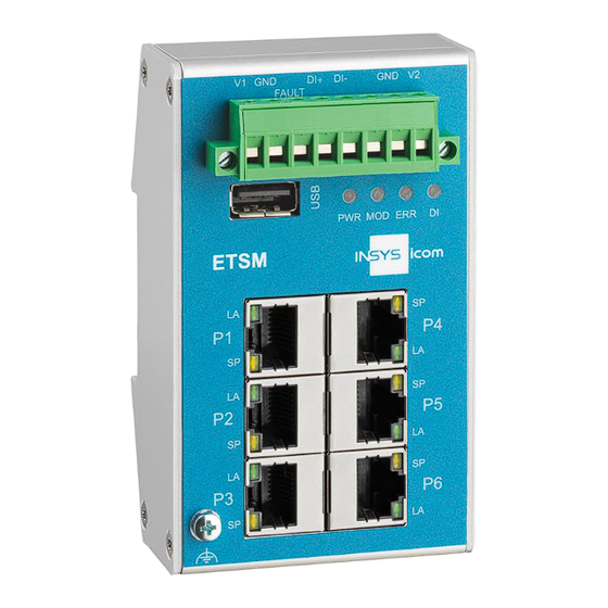
10/100 Mbit/s full/half duplex auto sense; automatic detection of "crossover" or "patch" wiring. USB interface USB 2.0 host; socket type A, max. 500 mA Table 2: ETSM/ETSU – technological features Connections and display elements Figure 1: ETSM / ETSU – connections and display elements... - Page 21 Fault Fault contact, potential-free (ETSM only) Ground Power supply, redundant positive terminal 2 Table 3 : ETSM / ETSU – push-in t erminal connector connections Figure 2: ETSM / ETSU – USB socket (ETSM o nly) Item Designation Description VBUS...
- Page 22 (10 Hz) perature supply failure (30 Hz) green Digital input inactive active Table 5 : ETSM – meaning o f t he display elements Colour Function green Supply V1 not connected / sufficient sufficient green Supply V2 not connected / sufficient sufficient Table 6 : ETSU –...
-
Page 23: Connecting The Connectors
Data rate 10 Mbit/s 100 Mbit/s Table 7 : ETSM / ETSU – meaning o f t he display elements at t he Ethernet port 7.2.1 Connecting the connectors The wires are contacted maintenance-free in the connector via screw terminal. -
Page 24: Assembly
Assembly ETSM / ETSU Assembly This section describes how to mount the switch to a DIN rail, connect the power supply and uninstall it again. Observe the instructions in the "Safety" section of this manual, in particular the "Safety Instructions for Electrical Installation"... - Page 25 ETSM / ETSU Assembly Connecting the power supply The device has already been mounted to the DIN rail. The power supply is connected and switched off. Remove the push-in terminal connector from the switch. Connect the ground lead of the power supply to the terminal "GND"...
-
Page 26: Commissioning, Operation And Configuration Etsu
Commissioning, Operation and Configuration ETSU ETSM / ETSU Commissioning, Operation and Configuration ETSU The unmanaged Switch ETSU does not require any configuration and is ready for operation directly upon switching it on. -
Page 27: Commissioning, Operation And Configuration Etsm
Commissioning, Operation and Configuration ETSM 10.1 Commissioning The lite-managed switch ETSM is delivered pre-configured. The factory configura- tion is set such that after powering the switch, the device transmits data to all Ethernet ports immediately. The following settings are set as default: •... -
Page 28: 0 .2 Operation Via The Web Interface
Commissioning, Operation and Configuration ETSM / ETSU ETSM 10.2 Operation via the web interface The configuration via the web interface allows you to change the device settings via the network. The IP address of the switch must be entered in the web browser to get access. - Page 29 ETSM / ETSU Commissioning, Operation and Configuration ETSM The left and upper part of the web interface will be displayed on all pages.. The left area is used for navigation and divided into the categories Monitoring, Con- figuration and Maintaining. Monitoring shows the states of various parts of the sys- tem.
-
Page 30: 0 .3 Supported Switch Configuration
Commissioning, Operation and Configuration ETSM / ETSU ETSM 10.3 Supported Switch Configuration 10.3.1 Ethernet Ports Configu- The setting of the Ethernet ports is carried out in the web interface under ration > Interfaces . The page contains two tables. The top shows the state of the... - Page 31 Only packets with TOS (type of service) or PCP (pri- ority code point) field higher than 3 are prioritized. Table 9 : ETSM – port settings Ports can be activated or deactivated using "Link Status". Deactivating unneeded ports is recommended if a link-down event shall be monitored.
-
Page 32: Port Mirroring
Commissioning, Operation and Configuration ETSM / ETSU ETSM 10.3.2 Port Mirroring Port mirroring (or port monitoring) allows to duplicate network traffic to an obser- vation port and analyse it there. The incoming and outgoing traffic can be dupli- cated independently per port. -
Page 33: Link Aggregation
ETSM / ETSU Commissioning, Operation and Configuration ETSM 10.3.3 Link Aggregation Link aggregation (also known as port trunking) allows to bundle several ports to en- able a higher redundancy or data throughput between two devices. Configuration > The link aggregation settings are made in the web interface under Link Aggregation Each interface can be assigned to Group A, Group B or no group (none). -
Page 34: Vlan
Commissioning, Operation and Configuration ETSM / ETSU ETSM 10.3.4 VLAN VLANs allow to segment a network and operate this like several small networks. VLANs can be configured in the web interface under Configuration > VLAN The configuration options are very flexible; connections between all ports and in each direction can be permitted or prohibited. - Page 35 ETSM / ETSU Commissioning, Operation and Configuration ETSM If different VLANs are connected with cables, problems with data transfer may occur. It is recommended to combine the respective VLANs.
-
Page 36: 0 .4 Device Diagno Sis
Internal device fault Digital input has triggered Table 1 0: ETSM – Failure conditions and codes The upper status bar of the web interface shows the actual status as text. The sta- tus codes are sent as trap messages. If several faults occur simultaneously, the sum is displayed. -
Page 37: Fault Contact
ETSM / ETSU Commissioning, Operation and Configuration ETSM 10.4.3 Fault contact The fault contact is used to signal occurring failure conditions. Devices that process this message can be connected to the fault contact. Con- The configuration of the Fault Contact is performed in the web interface under figuration >... -
Page 38: Traps
Commissioning, Operation and Configuration ETSM / ETSU ETSM 10.4.4 Traps Traps are used to signal failure conditions of the device. Traps are data packets that are sent to a configured network address via the network. This allows a monitoring at the destination address. -
Page 39: Diagnosis Services
ETSM / ETSU Commissioning, Operation and Configuration ETSM 10.4.5 Diagnosis services The diagnosis services allows to perform an automated diagnosis via network. SNMP and Modbus TCP are available for this. The services are configured under Configuration > Diagnostics. Diagnosis in ... - Page 40 Commissioning, Operation and Configuration ETSM / ETSU ETSM 10.4.5.2 Modbus TCP Modbus TCP allows to read the status of the network and the device. The Modbus TCP server is accessible on Modbus TCP standard port 502. The Modbus TCP server can only serve one client at once.
- Page 41 Table 1 1: ETSM – Mo dbus o ffsets It is possible to read multiple registers at once. However, it is to be observed that no invalid ranges are contained since the request will then be answered with a fail-...
-
Page 42: Digital Input
Commissioning, Operation and Configuration ETSM / ETSU ETSM 10.4.6 Digital input The device has a digital input. Any other device can be connected to it as far as the electrical specifications are complied with. The electrical properties and the con- nection of the fault contact are described in Technical Data. -
Page 43: Log Files
0 day(s) 00:00:30 fault contact inactive Table 1 2: ETSM – log entries The log file can also be downloaded from the device. To download the current log, Download Current Log Monitor- button is available in the web interface under ing >... -
Page 44: 0 .5 System Access Settings
Commissioning, Operation and Configuration ETSM / ETSU ETSM 10.5 System Access Settings 10.5.1 IP address Config- The configuration of the IP address is performed in the web interface under uration > System. The IP address, the subnet mask and the gateway can be config- ured there and transmitted to the device using the "submit"... -
Page 45: Administration Port
ETSM / ETSU Commissioning, Operation and Configuration ETSM 10.5.3 Administration port Access to the web interface of the device can be blocked on certain ports in order to limit device access. Configuration > Admin Inter- This can be configured in the web interface under faces. -
Page 46: Configuration Files
Commissioning, Operation and Configuration ETSM / ETSU ETSM 10.5.5 Configuration files The whole system configuration can be managed using configuration files. Maintaining > Settings. This can be made in the web interface under The following functions are supported: • Saving the configuration: o to an USB flash drive ("config.cfg") -
Page 47: 0 .6 Configuration Via Usb Flash Drive
ETSM / ETSU Commissioning, Operation and Configuration ETSM 10.6 Configuration via USB flash drive 10.6.1 Function The used USB flash drive must only have one partition and be formatted with FAT. The versions FAT12, FAT16 and FAT32 are supported. New data from an USB flash drive are only applied automatically if it is able to au- thenticate with a valid user name and password. -
Page 48: Firmware Update Via Web Interface
Commissioning, Operation and Configuration ETSM / ETSU ETSM 10.7 Firmware update A firmware update can be made using the web interface. Optionally, a firmware up- date can be made using USB flash drive. As long as a firmware update is running, the supply voltage must not be interrupted. -
Page 49: Firmware Update Via Usb Flash Drive
ETSM / ETSU Commissioning, Operation and Configuration ETSM 10.7.2 Firmware update via USB flash drive To install a firmware update via an USB flash drive, an USB flash drive that can be authenticated must be used (refer to respective section). An authentication file has to exist on the USB flash drive. -
Page 50: Maintenance, Repair And Troubleshooting
Repair Send defect devices with detailed failure description to the source of supply of your device. If you have purchased the device directly from INSYS icom, send the device to: INSYS MICROELECTRONICS GmbH, Hermann-Köhl-Str. 22, 93049 Regensburg. Before dispatching the device: •... -
Page 51: Waste Disposal
ETSM / ETSU Waste Disposal Waste Disposal 12.1 Repurchasing of Legacy Systems According to the new WEEE guidelines, the repurchasing and recycling of legacy systems for our clients is regulated as follows: Please send those legacy systems to the following address, carriage prepaid:... -
Page 52: Declaration Of Conformity
Declaration of Conformity ETSM / ETSU Declaration of Conformity Hereby, INSYS Microelectronics GmbH declares that herein described device types are in compliance with Directives 2014/30/EU and 2011/65/EU. The full text of the EC Declaration of Conformity is available under the following Internet address:... -
Page 53: Tables And Diagrams
Table 5: ETSM – meaning of the display elements ..........22 Table 6: ETSU – meaning of the display elements ..........22 Table 7: ETSM / ETSU – meaning of the display elements at the Ethernet port ..23 Table 8: Permissible wire cross-sections for connectors ........23 Table 9: ETSM –... -
Page 54: Index
Index ETSM / ETSU Index Accessories........18 Modification ......13, 50 Additional information ..... 8 Moisture ......... 12, 24 Alternative results......8 Open Source ......... 14 Assembly ........24 Operating voltage ......19 Auto-negotiation ......31 Overvoltage ........13 Breakdown........9 Overvoltage protection ....
Need help?
Do you have a question about the ETSM and is the answer not in the manual?
Questions and answers