
Related Manuals for Mobile Industrial Robots MiR 100

Summary of Contents for Mobile Industrial Robots MiR 100
- Page 1 October 2017 v.1.02017 v.1.2 with MiR Robot Interface 2.0 User Guide 08/2018 v1.1...
- Page 2 All rights reserved. No parts of this manual may be reproduced in any form without the express written permission of Mobile Industrial Robots ApS (MiR). MiR makes no warranties, express or implied, in respect of this document or its contents. In addition, the contents of the document is subject to change without prior notice.
-
Page 3: Table Of Contents
Table of contents 1 About this manual ......................3 1.1 Overview........................3 1.2 Document history ......................3 1.3 Where to find more information .................3 2 Safety ..........................4 2.1 Overview........................4 2.2 Safety concept ......................4 2.3 General safety instructions..................5 2.3 1 Warning notes ....................5 2.3 2 Caution notes....................6 2.3 3 Notices ......................7 2.4 Lithium battery ......................7 2.5 Safety circuit ........................8... - Page 4 8.1 1 Regular checks and maintenance tasks ............30 8.1 2 Regular checks and replacements ..............31 9 Repacking for transport ....................32 9.1 Preparations ......................32 9.2 Packing the robot for transportation.................33 A Payload specifications .......................34 B Connectors - pinout......................38 C Certificates ........................40 D Declaration of conformity....................42...
-
Page 5: About This Manual
It also includes necessary information about safe handling of the robot, technical specifications, troubleshooting and guidelines for proper maintenance of the robot. The User Guide is intended for Mobile Industrial Robots’ distributors as well as end users responsible for the daily operation of the MiR100™ robot. -
Page 6: Safety
Safety • • • • • • 2.1 Overview This manual contains notices you have to observe to ensure your personal safety, as well as to prevent damage to property. The notices referring to your personal safety are highlighted in the manual by a safety alert symbol. -
Page 7: General Safety Instructions
Safety 2.3 General safety instructions This section contains general safety notes. Some safety notes are repeated or further specified in other sections of the manual and further safety notes are present throughout the manual. 2.3.1 Warning notes • Ensure proper mounting of loads during transport Danger of personal injury from overturning robot or falling load. -
Page 8: Caution Notes
Safety 2.3.2 Caution notes • Do not use the robot to transport people Risk of personal injury and/or damage to the robot. The robot should never be used to transport people. This will revoke compliance with the standard EN 1525 Safety for unmanned trucks. -
Page 9: Notices
Safety 2.3.3 Notices • Indoor use only Risk of damage to the robot. The robot is made for indoor use only and should never be used outdoor. • Avoid small objects on the floor in the robot’s area Risk of property damage and/or minor damage to the robot. The robot cannot detect obstacles lower than 50 mm and may overrun smaller objects. -
Page 10: Safety Circuit
Safety 2.5 Safety circuit If a person or other moving object enters the safety zones of the robot where the planner due to response time, errors etc. does not respond, the safety circuit will force the robot into emergency stop, and the robot stops immediately. When the person or object is out of the safety zone again, the robot will automatically reset the emergency stop. -
Page 11: Certifications
Certifications • • • • • • 3.1 Overview This chapter presents certificates and declarations applying to the robot. Copies of the CE declarations of conformity in various languages and 3rd party certificates are posted and can be downloaded from the Distributor login site: (http://www.mir-robots.com/ downloads/certificates). - Page 12 Certifications Reference of the other technical standards and specifications used: Ref. no. Title EN 1525:1997-09 Safety of industrial trucks – Driverless trucks and their systems See also signed copy of Declaration of conformity in Appendix D on page 42. • •...
-
Page 13: Getting Started
Getting started Getting started • • • • • • 4.1 In the box Figure 4.1. The shipment 1. The robot 2. MiR100 Kit • Emergency stop box, external antenna and 4 pcs. M10x40 bolts • Two charging cables, one for 110 V and one for 220 V 3. -
Page 14: Unpacking The Mir100
Getting started 4.2 Unpacking the MiR100™ 4.2.1 Unboxing Follow these steps to unbox the MiR100™ Step Action Remove pallet lid and take out the box with the MiR100 kit. Remove the top foam, foam blocks on the sides and the pallet frames. Place the pallet cover as a ramp at the robot’s rear end. -
Page 15: Powering Up
Getting started 4.2.2 Powering up Step Action Grab the two rounded corners and carefully lift off the cover. Connect one of the two battery cables to the plug Switch on the four relays placed in the corner by the on top of the battery box. front laser scanner. - Page 16 Getting started Step Action Carefully fit the cover correctly over the Mount and connect the emergency stop box on top connector openings. of the robot cover. If a top module is going to be mounted on top of the robot, the emergency stop must be placed in a position where it is easy to reach.
- Page 17 Getting started Step Action Push the blue power button in the corner to turn Press the reset button on the emergency stop when on the robot. it has lit up. The robot lights up with a yellow running light for The robot light now switches to yellow constant light, a short moment, then enters emergency stop indicating that the robot is paused and ready to...
-
Page 18: Getting Connected
Getting started 4.3 Getting connected Step Action On a PC, tablet or smartphone, go to the WiFi menu, find the name of your robot and connect to it. Open a browser and go to mir.com. Log in to the MiR Robot. Access name and passwords required to log on to the robot’s... -
Page 19: Charging The Robot
Getting started 4.4 Charging the robot The robot arrives with a charged battery and can drive for up to three hours before recharging is required. Follow these steps to charge the robot using the enclosed charging cable: Step Action Remove the rear corner by pulling it towards Then connect the charging cable to the robot’s you. -
Page 20: Testing The Robot
Getting started 4.5 Testing the robot Before using the robot, you are recommended to check that all components and processes inside the robot work as intended. 1. Log on to the MiR Robot interface, see Getting connected on page 16. 2. -
Page 21: Shutting Down The Robot
Getting started 4.6 Shutting down the robot Follow these steps to shut down the robot correctly. Step Action Bring the robot to a halt. Then push the blue on/ Wait for the light on the robot to turn off button to turn off the robot. The light switches off. -
Page 22: Product Presentation
The identification label of the MiR100™ is placed on the back of the battery box. Figure 5.1. Example of MiR100™ CE marking and identification label • CE Mobile Industrial Robots ApS declares that the MiR100™ meets the requirements of the applicable EC directives. See Declaration of conformity on page 34 •... -
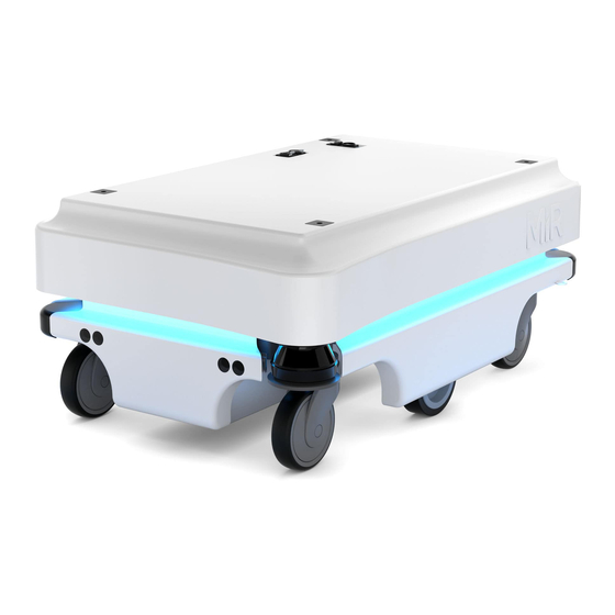
Page 23: Mir100™ Outer Parts
Product presentation 5.3 MiR100™ Outer parts Figure 5.2. MiR100™ Outer parts 1. Top cover 11. Behind removable rear corner cover: Charging port with switch 2. Caster wheel - all four corner wheels 12. Rear cover 3. Drive wheel - differential control 13. -
Page 24: Mir100™ Inner Parts
Product presentation 5.4 MiR100™ Inner parts Figure 5.3. MiR100™ Inner parts 1. Breaker - automatic fuse between battery and 10. Battery with connector - main power to the components robot 2. Solid state relay - releases the latching relay (pos. 11. -
Page 25: Sensor Systems
Product presentation 5.5 Sensor systems The MiR100™ has a number of internal and external safety sensors to secure safe operation among people and equipment. External External sensors (see alsoMiR100™ Outer parts on page 21) sensors • 3D camera Intel RealSense™ Detection of objects in front of robot: •... - Page 26 Product presentation Figure 5.5. The laser scanners detect objects 200 mm above ground and the 3D camera detects objects from ground level and up to 995 mm above ground Safety zones The MiR Safety zones change depending on the speed of the robot. The speed regulations are as follows for the front scanner: Zone name Speed minimum...
-
Page 27: Light Indicators
Product presentation 5.6 Light indicators The light indicators on the MiR100™ indicate current operational state. Colors may be adapted to individual user needs, but the robot is delivered with the following setup. Figure 5.6. MiR100™ light indicators 5.7 Main features of the MiR100™ •... -
Page 28: Applications
Applications • • • • • • 6.1 Overview The MiR100™ can be equipped with a range of applications to suit the specific purpose the robot will be used for. Some are user-provided and others are purchased directly from Mobile Industrial Robots. -
Page 29: Technical Specifications
Technical specifications • • • • • • 7.1 Main specifications Dimensions Length 890 mm Width 580 mm Height 352 mm Height above floor 50 mm Weight (without load) 62.5 kg Load surface 600 x 800 mm Color Pure white: RAL 9010 Payload Robot payload 100 kg (maximum 5% incline) - Page 30 Technical specifications Power Battery Li-NMC, 24 V, 40 Ah; charging time: up to 3 hours (0-80% in 2 hours) See safety notes for the battery in “Lithium battery” on page 7. See also requirements for battery transportation in “Repacking for transport” on page 29.
-
Page 31: Dimension Drawing
Technical specifications Top module Max height from floor to top 1800 mm Center of gravity Lower than 900 mm above the floor 7.2 Dimension drawing Figure 1. Dimensions of the MiR100™ • • • MiR100™ User Guide, Robot Interface 2.0, 08/2018 v.1.1 •... -
Page 32: Maintenance
Maintenance • • • • • • 8.1 Overview The following maintenance schedules give an overview of regular cleaning and parts replacement procedures. The stated intervals are indicative and depend on the operating environment and frequency of usage of the robot. 8.1.1 Regular checks and maintenance tasks Weekly Once a week carry out the following maintenance tasks:... -
Page 33: Regular Checks And Replacements
Maintenance 8.1.2 Regular checks and replacements Before starting replacement tasks that involve removal of the shield: • Press the On/Off button to turn off the robot • Push the battery switch button to remove power from the battery • Remove the cover and unplug the ESD cable if applied, see Getting connected on page 15 •... -
Page 34: Repacking For Transport
Repacking for transport • • • • • • 9.1 Preparations Packaging Use the original packaging when transporting the robot. Figure 9.1. The original packing material consists of pallet bottom and top plates, pallet frames, foam blocks and foam top layer. Battery The lithium battery is subject to transport regulations, see Caution below. -
Page 35: Packing The Robot For Transportation
Repacking for transport 9.2 Packing the robot for transportation Before packing the robot, it must be shut down as follows: 1. Bring the robot to a halt and push the blue power button to turn off the robot. 2. Turn off the battery disconnect switch (the two yellow indicators pointing to Off). To pack the robot, reverse the steps of the unpacking procedure, see “Unpacking the MiR100™”... -
Page 36: A Payload Specifications
A Payload specifications • • • • • • The following drawings illustrate the center of mass (CoM) specifications for safe operation at different payloads. The specifications apply to payloads of: • 25 kg • 50 kg • 75 kg •... - Page 37 1400 1400 1200 1200 1000 1000 1000 1000 Units: mm 50kg payload • • • MiR100™ User Guide, Robot Interface 2.0, 08/2018 v.1.1 • • •...
- Page 38 1400 1400 1200 1200 1000 1000 1000 1000 Units: mm 75kg payload • • • MiR100™ User Guide, Robot Interface 2.0, 08/2018 v.1.1 • • •...
- Page 39 1400 1400 1200 1200 1000 1000 1000 1000 Units: mm 100kg payload • • • MiR100™ User Guide, Robot Interface 2.0, 08/2018 v.1.1 • • •...
-
Page 40: B Connectors - Pinout
B Connectors - pinout • • • • • • B.1 Application interface Pin number Signal name Max. current Remarks Battery voltage Starts with the robot Battery voltage Starts with the robot Battery voltage Stops by emergency stop Ground Figure 1. Application interface •... - Page 41 B.2 Emergency stop Pin number Signal name Remarks DIN 19 DIN 14 DIN 70 E-stop, 1 GN E-stop, 2, GN-WH/RD Reset button, BWN-WH SICK XTIO, Q3 For Sick Scanner For Sick scanner To use with the 24V signal from pin 10 24V max.
-
Page 42: C Certificates
C Certificates • • • • • • C.1 Particle emission (Cleanroom) • • • MiR100™ User Guide, Robot Interface 2.0, 08/2018 v.1.1 • • •... - Page 43 • • • MiR100™ User Guide, Robot Interface 2.0, 08/2018 v.1.1 • • •...
-
Page 44: D Declaration Of Conformity
D Declaration of conformity • • • • • • • • • MiR100™ User Guide, Robot interface 2.0, 08/2018 v.1.1 • • •...
Need help?
Do you have a question about the MiR 100 and is the answer not in the manual?
Questions and answers