Table of Contents
Advertisement
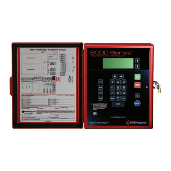
Single Well Plunger Lift Controller Manual
®
®
The 8000 Series
brand is trademarked by PCS Ferguson
.
These documents and materials are copyrighted by PCS Ferguson.
© 2017 All rights reserved.
For information contact:
PCS Ferguson
3771 Eureka Way
Frederick, CO 80516
Phone: 720-407-3550
Fax: 720-407-3540
Email: information@pcsferguson.com
Website: www.doverals.com/pcsferguson
1
Advertisement
Table of Contents

Summary of Contents for PCS Ferguson 8000 Series
- Page 1 Single Well Plunger Lift Controller Manual ® ® The 8000 Series brand is trademarked by PCS Ferguson These documents and materials are copyrighted by PCS Ferguson. © 2017 All rights reserved. For information contact: PCS Ferguson 3771 Eureka Way Frederick, CO 80516...
-
Page 2: Table Of Contents
Single Well Plunger Lift Controller Manual 1 Contents 1 Understanding Plunger Lift Operations . . . . . . . . . . . . . . . . . . . . . . . . . . . . . . . . . . . . . . . . . . . . . . . . . . . . . . .8 1.1 Components . - Page 3 Single Well Plunger Lift Controller Manual 2.1.9 B Open Time (All Production Methods) ..........30 2.1.10 B Delay Time (All Production Methods) .
- Page 4 4 8000 Series Walkup Display and Keypad Commands . . . . . . . . . . . . . . . .
- Page 5 Single Well Plunger Lift Controller Manual 5.1 On Site Communication with an 8000 Series Controller ......56 5.2 Off Site Communication with an 8000 Series Controller .
- Page 6 Worksheet . . . . . . . . . . . . . . . . . . . . . . . . . . . . . . . .83 Appendix B: 8000 Series Agency Approval .
- Page 7 Single Well Plunger Lift Controller Manual Revision History Date Description Version 6/1/2017 Initial Release...
-
Page 8: Understanding Plunger Lift
Single Well Plunger Lift Controller Manual 1 Understanding Plunger Lift Operations Over time, a well’s gas production declines but a plunger lift system can increase a well’s productivity and life span. The natural pressure that lifts the gas from the well to the surface declines. - Page 9 Single Well Plunger Lift Controller Manual Figure 1.1 The basic components of the Plunger Lift System in place Understanding Plunger Lift Operations...
-
Page 10: Conditional Modes Of The Plunger Cycle
Single Well Plunger Lift Controller Manual 1.2 Plunger Lift Cycle The plunger system lifts the liquids using pressure from the gas flow. The plunger moves between the bottom hole bumper spring and the lubricator at the top of the well. The Motor Valve controls physical flow of the gas. -
Page 11: Optimization Programs, Production Methods, And Set
Single Well Plunger Lift Controller Manual The primary set point for this mode is a time setting. However, the controller can use a pressure setting on the Casing to enter this mode. For example, if the plunger does not arrive during the time specified for the set point, A Open, the controller counts down the time interval specified by the set point and detects that the pressure on the casing is lower. -
Page 12: Time Method
Single Well Plunger Lift Controller Manual user can choose from several production methods. Each method employs specific primary set points and a group of associated set points. These set points allow the user to customize movement between the modes in response to well conditions. The user can disable any set point by entering zero or a value too high to occur. -
Page 13: Other Conditional Modes And Set Points
Single Well Plunger Lift Controller Manual the controller detected the High Line Shut-In pressure and the results of the sampling during the time set in High Line Pressure Shut-in Delay. If the pressure sampling reveals the pressure temporarily spiked and then fell, the Well Program returns to the previous mode. -
Page 14: Autocycle Program
Single Well Plunger Lift Controller Manual For each of these methods, the user specifies a differential in pressure based on the well’s conditions. The primary set point is Differential Open Pressure. The set point answers the question: “At what pressure difference, does the user want the Well Program to enter A OPEN mode?” Time still plays a role as the controller counts down Fall Time before evaluating the pressure differential. - Page 15 Single Well Plunger Lift Controller Manual The following figure shows the basic plunger cycle and where the AutoCycle program windows affect production. The following paragraphs provide more detail about the windows and their associated parameters. 1 .6 .2 Plunger Arrival Windows The AutoCycle program makes the same adjustments to the Afterflow Time and Off Time that an on-site operator would make while tending the well.
- Page 16 Single Well Plunger Lift Controller Manual The user provides set points for times typical to the well. These set points define the windows of time so that the AutoCycle program can adjust the settings correctly. The arrival windows are dependent on the amount of time it takes for the plunger to reach the surface after the production valve (Tubing Valve) is open.
-
Page 17: Plunger Arrival Counts
Single Well Plunger Lift Controller Manual The figure below shows the AutoCycle tab. The user can accept default values that are based on a depth of 8000 feet. The program can meet any level of control the user might want to apply. The user can supply an initial set of times specific to the well and allow the AutoCycle program to adjust automatically. - Page 18 Single Well Plunger Lift Controller Manual The counters for Slow and No Plunger reset to the initial value immediately upon a Fast or Good arrival. The Early counter resets upon a Slow or No Plunger arrival. The counters for Fast and Good arrivals reset upon a Slow or No Plunger arrival.
- Page 19 Single Well Plunger Lift Controller Manual The same is true for the Good window default values. Notice that good arrivals have associated set points and not adjustments. • Current Afterflow (Sales Time) • Current Off-Time (Close Time) • Min Off-Time (Fall Time) •...
-
Page 20: Automatic Time Adjustments
Single Well Plunger Lift Controller Manual The following section describes the adjustments for the arrival windows and the set points of the Good Window. 1 .6 .4 Automatic Time Adjustments The AutoCycle program compares the actual time of arrival with the values of the window set points. -
Page 21: Autocycle Pressure Set Points
Single Well Plunger Lift Controller Manual NOTE Best Practice If the arrival time is very close to the Good Arrival window use the option for proportional adjustment. 1 .6 .5 AutoCycle Pressure Set Points The user can set the program to respond to pressure readings by using the Pressure Overrides feature. -
Page 22: Automatic Adjustment Of Pressure Set Points
Single Well Plunger Lift Controller Manual The figure below shows the AutoCycle Pressure Overrides dialog box. Figure 1.7 The dialog box for pressure set points By using the pressure overrides, the user sets the program to respond to the current pressure readings in addition to the passing of time. - Page 23 Single Well Plunger Lift Controller Manual 1 .6 .6 Automatic Adjustment of Pressure Set Points The user can set the program to adjust the pressure set points for the next cycle based on the plunger arrival. Figure 1.8 Adjustments to Pressures for the Arrival Windows After the user has enabled the program, the user can analyze the results of the optimization program.
-
Page 24: Set Points For Plunger Lift
Single Well Plunger Lift Controller Manual 2 Set Points for Plunger Lift Operations The user can analyze the well’s performance over time and fine-tune the production method based on trending data. A user examines a current analysis of a well’s performance to set and adjust the frequency of the plunger cycles based on conditions of the well. -
Page 25: Fall Time (All Production Methods)
Single Well Plunger Lift Controller Manual Figure 2.1 Program Values area shows the set points available based on the production method 2 .1 .1 Fall Time (All Production Methods) Format: HH:MM:SS Oypical Value: 1:00:00 Disable Value: 00:00:00 Specify a minimum shut-in time to allow the plunger to fall to the bottom of the well. During Fall Time, the user must use the Go to A open mode on the Status tab of the well or use the ON button on the Walk Up Display to open the well. -
Page 26: A Open Time (All Production Methods)
Single Well Plunger Lift Controller Manual 2 .1 .3 A Open Time (All Production Methods) Format: HH:MM:SS Oypical Value: Time method: 1:00:00 Legacy Label: Open Time, TUBING ON for the Sales valve Specify the time that the well is open and gas is flowing through the production valve. During Open Time, the plunger starts to surface and the well produces its initial head gas. -
Page 27: Mandatory Shut-In Time (All Production Methods)
Single Well Plunger Lift Controller Manual NOTE If the D.I.P. Close Pressure is set to 1, 2, or 3 psi, set Delay Close Time to 10, 20, or 30 seconds. Under most conditions, this set point provides time for gas to clear remaining liquids out of the line into the separator. This practice can prevent water from freezing and damaging the line in cold temperatures. -
Page 28: High Line Pressure Shut-In Delay (All Production Methods)
Single Well Plunger Lift Controller Manual Usage: For example, assume that the value for Casing Peak Pressure Time is 10 minutes. After the production valve closes, the controller counts down the Casing Peak Pressure Time. If the pressure builds 1 psi after 7 minutes and the counter for Fall Time reaches zero, the controller restarts the countdown of Casing Peak Pressure Time. -
Page 29: B Delay Time (All Production Methods)
Single Well Plunger Lift Controller Manual 2 .1 .10 B Delay Time (All Production Methods) NOTE Format: HH.MM.SS Disable Value: 00:00:00 Legacy Label: TANK DELAY for the Vent valve Specify additional time to keep the tank valve open after a plunger arrival. Usage: This period is after the arrival of the plunger and before the close of the tank valve. - Page 30 Single Well Plunger Lift Controller Manual Casing - Tubing Load Factor X 100 Casing - Line Figure 2.2 Load Factor This ratio can indicate if pressure in the well is strong enough to lift the liquid load in the tubing. If the Load Factor (Fluid Slug) setpoint is greater than zero (>...
-
Page 31: Casing Drop Pressure (Pressure Methods)
Single Well Plunger Lift Controller Manual 2 .1 .13 Casing Drop Pressure (Pressure Methods) Format: Pressure value (psi) Disable Value: 0 Specify the drop in the casing pressure that can initiate the Sales Time countdown without input from the Arrival Sensor. Usage: Specify this set point as a backup in the following cases: The Arrival Sensor fails to detect a plunger arrival ... -
Page 32: Control Exit Of Sales Mode (Pressure Methods Only)
Single Well Plunger Lift Controller Manual To use Casing Drop Pressure as a backup arrival sensor From the raw data in the data logs, note the Casing pressure the moment the production valve opens and when the plunger surfaces. The figure below shows the two values: 472 and 405. Figure 2.3 The datalog shows the pressure values Calculate the difference and add 10-15 psi. -
Page 33: Close Pressure (Pressure Methods)
Single Well Plunger Lift Controller Manual 2 .2 .1 D .I .P . Close Pressure (Pressure Methods) Format: Pressure value (psi) Oypical Value: 1, 2, or 3 psi for many wells Disable Value: 0 Legacy Label: Differential Close Pressure Specify the minimum pressure difference that causes the controller to close the well and the Well Program to exit SALES mode. -
Page 34: Control Shut-In
Single Well Plunger Lift Controller Manual Specify a gas constant to compensate for pressure fluctuations on the Sales Line and to prevent liquids from returning into the tubing. The Well Program can use this set point along with the Gas Low Flow Close Rate to prevent low pressure on the Sales Line. -
Page 35: Set Points For The Autocycle
Single Well Plunger Lift Controller Manual 3 Set Points for the AutoCycle ™ Program The user can configure the AutoCycle program to analyze the well's performance over time and fine-tune the production method based on the speed of the plunger. The user enters a set of time values that categorizes the arrivals. -
Page 36: Reset Defaults Button
Single Well Plunger Lift Controller Manual • Fast Window Plunger runtime between the values for Early Window and Fast Window. Without the Early Window enabled, the Fast Window is between the start of Tubing ON Time and the value for Fast Window. •... -
Page 37: Current Count In The Early Window Area
Single Well Plunger Lift Controller Manual 3 .2 .4 Current Count in the Early Window area Format: ## Oypical Value: 2 Legacy Keypad Command: 29 Legacy Label: CURRENT EARLY After the initial setting by the user, this counter indicates the number of consecutive arrivals that have occurred within the Early Window. -
Page 38: Current In The Fast Window Area
Single Well Plunger Lift Controller Manual 3 .3 .3 Current in the Fast Window area Format: ## Oypical Value: Equal to the Initial value for the Fast Window Legacy Keypad Command: 16 Legacy Label: CURRENT FAST After the initial setting by the user, this counter indicates the number of arrivals that have occurred within the Fast Window. -
Page 39: Good Window Area
Single Well Plunger Lift Controller Manual 3.4 Good Window Area This area provides the limits for the window and the set points that define a good arrival. 3 .4 .1 No Label (Hr Min Sec) Format: HH:MM:SS Oypical Value: Tubing depth/600 Legacy Keypad Command: 02 Legacy Label: SLOW TIME Specify the time that sets the limit between Good Window and Slow Window. -
Page 40: History Read Only)
Single Well Plunger Lift Controller Manual 3 .4 .4 (History Read Only) Format: ## Legacy Keypad Command: 52 Legacy Label: ARRIVAL HISTORY Indicates the number of plunger arrivals within this window. This value accumulates from the time the user selected the Clear Totals button. 3 .4 .5 Current Afterflow in the Good Window area Format: HH:MM:SS Oypical Value:... -
Page 41: Min Off-Time
Single Well Plunger Lift Controller Manual 3 .4 .7 Min Off-Time Format: HH:MM:SS Oypical Value: Tubing Depth / 200 Legacy Keypad Command: 05 Legacy Label: MIN OFF Specify the lowest value that the program can reduce the Current Off-Time. This value ensures that the plunger has time to reach the bottom of the tubing before the well opens. -
Page 42: Slow Window Area
Single Well Plunger Lift Controller Manual 3.5 Slow Window Area 3 .5 .1 Current On-Time Format: HH:MM:SS Oypical Value: Tubing depth/400 Legacy Keypad Command: 03 Legacy Label: TUBING ON Specify the maximum amount of time the well is open and waiting for the plunger to arrive. This value sets the boundary between the Slow Window and No Plunger. -
Page 43: History Read-Only)
Single Well Plunger Lift Controller Manual 3 .5 .4 (History Read-Only) Format: ## Legacy Keypad Command: 52 Legacy Label Indicates the number of plunger arrivals within this window. This value accumulates from the time the user selected the Clear Totals button. 3 .5 .5 Deduct from Afterflow in Slow Window Format: HH:MM:SS Oypical Value: 5-15 minutes... -
Page 44: No Plunger Area
Single Well Plunger Lift Controller Manual 3.6 No Plunger Area 3 .6 .1 Initial in the No Plunger area Format: ## Oypical Value: 3 Legacy Keypad Command: 21 Legacy Label: INITIAL N/A: Specify the number of arrivals that occur after Current Afterflow expires before the well enters CLOSE (TUBING OFF) mode and the controller applies the adjustment to Current Off-Time. -
Page 45: Pressure Overrides
Single Well Plunger Lift Controller Manual Specify the highest value that the controller can increase the Off Time using adjustments. A high value, such as the default of 99:59:59 allows the controller to make unlimited adjustments but does set a limit should the well conditions require it. 3.7 Pressure Overrides The following table summarizes the set points available on the Pressure Overrides dialog box. -
Page 46: Plunger Open Adjustments
Single Well Plunger Lift Controller Manual 3 .7 .3 Plunger Open Adjustments Label Purpose CP (-) for Fast Open if CP >= decrease adjustment for Fast Arrival. CP (+) for Slow Open if CP >= increase adjustment for Slow Arrival. CP (+) for None Open if CP >= increase adjustment for No Arrival. -
Page 47: Safety Shut-Down (Psig) Area
Single Well Plunger Lift Controller Manual 3 .7 .5 Safety Shut-Down (PSIG) Area Label Purpose MAX CP >= Specify the highest Casing Pressure the controller uses to close the well to prevent damage to the well site. MAX TP <= Specify the highest Tubing Pressure that the controller uses to close the well. -
Page 48: 8000 Series Walkup Display And Keypad Commands
4 8000 Series Walkup Display and Keypad Commands The 8000 Series master controllers have a Walk Up display in a case at the site. This display provides the user with a keypad interface to the well automation system. This keypad interface connects directly to the controller. - Page 49 Some well sites use Walk Up Display security to require the user to enter access codes. With security enabled, the 8000 Series controllers require the user to enter a four (4) digit PIN. The WellVision application offers this feature through the Keypad Config button on the Setup tab of controller.
-
Page 50: The Single-Well ™ Application Keypad Commands
READ/SET 15 Low Line Close Pressure * Indicates commands that require an administrator PIN if the keypad is using the Walk Up Display security feature Table 4.2 Commonly Used Commands for the Single-Well Application 8000 Series Walkup Display and Keypad Commands... -
Page 51: The Autocycle ™ Program Keypad Commands
Initial Fast Plunger Arrival Count READ/SET 116 Current Fast Plunger Arrival Count READ/SET 117 Initial Good Plunger Arrival Count READ/SET 118 Current Good Plunger Arrival Count READ/SET 119 Initial Slow Plunger Arrival Count 8000 Series Walkup Display and Keypad Commands... - Page 52 READ/SET 168 Open if Tubing Pressure-Line Pressure > than the set point READ/SET 169 Open if Fluid Slug >= to the set point READ/SET 170 Open if Casing Pressure >= to the set point 8000 Series Walkup Display and Keypad Commands...
- Page 53 READ/SET 195 Maximum Tubing Pressure Shut in Indicates commands that require an administrator PIN if the keypad is using the Walk Up Display security feature Table 4.3 8000 Series Commands for the AutoCycle Program 8000 Series Walkup Display and Keypad Commands...
-
Page 54: Understanding Well Site
Figure 5.1 A connection with a USB cable A user can connect through a laptop or a mobile device to the automation system. The 8000 Series controller needs an onboard Bluetooth® communication module to pair with a mobile device that is Bluetooth capable. -
Page 55: Off Site Communication With An 8000 Series Controller
Figure 5.3 A connection with TCP/IP Setup of this communications network is outside the scope of this document. For more information about customizing the 8000 Series controllers to an existing system or a designing a new system, contact a PCS Ferguson sales and service representative. -
Page 56: Well Networks
5 .3 .2 The 8000 Series Controllers on a Well Network The 8000 Series Controllers are capable of wired and/or wireless communication. The following figure is a basic example of one well using automation to monitor devices and to optimize production with a plunger lift system. -
Page 57: Wireless Communications
Single Well Plunger Lift Controller Manual Figure 5.4 A Single-Well controller showing wireless and wired options The following sections show the wireless and wired options for the 8000 Series Controllers. 5 .3 .3 Wireless Communications The well network can use a variety of radios for communicating. -
Page 58: Wired Communications
Figure 5.6 RS-485 ports on a circuit board 5.4 Security Access Codes The PCS Ferguson 8000 Series components have two areas that the user can implement security access codes. Remote Access Security The user can add a security code to a wellhead controller. After enabling this feature, the WellVision application requests the code if the user connects with a remote connection. - Page 59 Single Well Plunger Lift Controller Manual Figure 5.7 Access Codes Limit the Available Commands on the Walk Up Display The user can configure ten (10) unique administrator codes and ten (10) unique operator codes. Code assignments and policy decisions are not within the scope of this document. Operator access allows the user to complete most operations and settings for well operations.
-
Page 60: Monitoring Tank Levels
Single Well Plunger Lift Controller Manual 6 Monitoring Tank Levels The 8800 Site Manager or 8400™ controllers can monitor and respond to devices that measure levels ™ in the tanks of a well system. The tank management devices can connect directly to the master control- ler, a slave controller, or a remote IO device. -
Page 61: Tank Settings
Figure 6.2 The System Setup for Tank Management 6 .1 .2 Tank Settings The PCS Ferguson Tank Management system can manage up to 24 tanks. Each row in the figure below represents one tank configuration. For each tank, the user identifies the communications for each device that provides input to the controller. -
Page 62: Alarms And Shut-Ins
Single Well Plunger Lift Controller Manual 6 .1 .3 Alarms and Shut-Ins The user can set alarm and automatic shut in conditions based on the tank level readings. For example, the figure below indicates that both the level of the tank and the number of communications error can raise a warning or shut-in the well. -
Page 63: Polling Interval
This connection could be through the radio network or a cellular modem. The user needs to use the Resume Well Operation button available on the Status tab of PCS Ferguson Tank Management System. Allow the command from the host or the keypad The user can start operations using ... -
Page 64: Preparation
Respond to warnings and shut in events 6.4 Configure Tanks The user needs to add the information for the tank to the PCS Ferguson Tank Management system. The system is available from the Status tab. The system provides the user with features to complete the following tasks: •... -
Page 65: Importing An Oleumtech Or Ilevel Tank Configuration File
In WellVision, connect to the controller. On the Status tab, select the Oank Level button. On the Oank Setup tab of the PCS Ferguson Oank Management System window, select the Import iLevel or Nleum settings button. In the Import dialog box, locate and select the .csv file for the tank configuration and then select the Npen button. - Page 66 Single Well Plunger Lift Controller Manual Figure 6.5 Each row represents a tank and associated inputs, dimensions, and alarm values On the Tank Setup tab, enter a name in the Tank Name column. In the columns, Top Fluid Level – COMMS Errors, select the cell in the column to open the Modbus Setup dialog box and enter the Modbus Register information from the base unit for the probes and then select the OK button.
-
Page 67: Tank System Configuration
Single Well Plunger Lift Controller Manual Figure 6.7 Tank Height In the Warning and Shut-in columns, select the cell and enter the values for the maximum and minimum levels, and then select the OK button. NOTE For the maximum values, the application automatically updates the other values the user enters a percentage or feet and inches. -
Page 68: Monitoring Levels In The Tanks
[Optional] If memory is a concern, select Memory Use TEstimate. For more information, see the section on Polling Interval earlier in this document. 6.6 Monitoring Levels in the Tanks The user can configure and monitor tank level devices in WellVision such as PCS Ferguson’s iTank or OleumTech. 6 .6 .1 Review Current Status The user might want to review the status of the tanks. -
Page 69: Review Tank Trends
Single Well Plunger Lift Controller Manual To review the status of the tanks Open WellVision and connect to the controller. On the Status tab, select the Oank Level button. Figure 6.10 The Status tab Examine the information. To update the display, select the Refresh button. If appropriate, select Resume Well Nperation button. - Page 70 Single Well Plunger Lift Controller Manual Figure 6.11 The Trend Tab To view trend data for the tanks On the Orend tab, select Upload Orend Data. In the Upload dialog box, select the box next to the dates the user wants to view and then select the Upload button.
- Page 71 Single Well Plunger Lift Controller Manual Figure 6.12 Upload window displays the available log files Select the View data button to open the View Datalogs window with tabs for each log. To close the window, select the Red X button. Monitoring Tank Levels...
-
Page 72: Respond To Tank Level Alarms
Single Well Plunger Lift Controller Manual 6 .6 .3 Respond to Tank Level Alarms If the controller detected levels that match the warning or shut-in values set in the configuration, the application raises a warning or closes the wells. To respond to a tank level alarm Open WellVision and connect to the 8800 Site Manager or 8400 controller. - Page 73 Single Well Plunger Lift Controller Manual On the Status tab, select the alarm to open the Warning and Shut-in dialog box. Figure 6.14 Warnings and Shut-ins Window Examine the information and select Acknowledge, and then select the Close button. For example, in the figure above, the controller detected that the tank’s fluid level matched the maximum in the configuration settings.
-
Page 74: Viewing Graphs Of Well
Single Well Plunger Lift Controller Manual 7 Viewing Graphs of Well Performance To make optimization decisions, the user can examine graphs showing well performance over time. The controller uses the raw data from the input and output devices to generate a trend graph. A graph provides the user with practical information to make decisions about adjustments to the well program. -
Page 75: View A Basic Well Trending Graph
Single Well Plunger Lift Controller Manual 7.3 View a Basic Well Trending Graph A graph shows performance of a well over a time interval. The graph uses values from the datalog, Log1: Well Control. The WellVision uses the log data to calculate values for additional data points on the graph. - Page 76 Single Well Plunger Lift Controller Manual Figure 7.2 The keys describe the symbols and colors in the graph To show a specific date, select the Start Date button and then select a day from the Select Date dialog box. NOTE The display shows only data from dates available on the computer.
-
Page 77: View A Summary Of Data Within A Timeframe
Single Well Plunger Lift Controller Manual Figure 7.3 The user can change time interval of the display To add production to the graph, select the Daily Production button. To print the graph, select the Print button on the toolbar. 7.4 View a Summary of Data within a Timeframe The user might want to see the performance data summarized. -
Page 78: View Details And Calculations Within A Timeframe
Single Well Plunger Lift Controller Manual Figure 7.4 Calculations use raw data to show summary values for the select data To close the window, select the Red X button. [Optional] To add other information to the graph, select the Configure button to open the Configuration window and use the Optional Traces feature. - Page 79 Single Well Plunger Lift Controller Manual Figure 7.5 The Markers table shows calculations using the marked data points Select and position the markers around a pressure event. Move the cursor to examine a specific position on the graph. Examine the table and adjust the lines and cursor to change the results. To examine the corresponding raw data, select the Oile button or Raw Data button.
- Page 80 Single Well Plunger Lift Controller Manual To view values in the columns, scroll. Column Description Date Timestamp from the Well Trend log Daily Production Casing Pressure reading from the Well Trend log Tubing Pressure reading from the Well Trend log Line Pressure reading from the Well Trend log Flow...
- Page 81 Single Well Plunger Lift Controller Manual Appendix A: Single Well I/O Worksheet The user can complete the following worksheet to verify that the well system has the components needed to set up plunger lift operations on their well. For more information about well program configuration, see "Configuring a Single Well"...
- Page 82 Class I, Division 2 hazardous areas. NOTE PCS Ferguson 8800 Series components must be connected to a power source (i.e. solar panel) rated 12V dc nominal, 26V dc maximum, open circuit: 8A nominal, 10.5A maximum short circuit and appropriately certified for the location.
- Page 83 Single Well Plunger Lift Controller Manual...
- Page 84 Single Well Plunger Lift Controller Manual...
Need help?
Do you have a question about the 8000 Series and is the answer not in the manual?
Questions and answers
I keep getting a communication error when trying to set on and off times
To fix a communication error when setting On and Off times for the PCS Ferguson 8000 Series, check the following:
1. Poll Interval: Ensure the poll interval is not set too short. A short interval (less than 5 minutes) may cause Modbus communication errors.
2. Modbus Address: Verify that the Modbus address is correctly set in the System Setup tab.
3. Tank Configuration File: If settings were saved in a .csv file, reload and update the configuration to match the current system setup.
4. Controller Limits: Ensure that the Off Time does not exceed the Maximum Off Time set point, as the controller may ignore excessive values.
5. Legacy Commands: Use the correct legacy keypad commands to adjust Current On Time (03) and Current Off Time (04).
If the issue persists, adjust the settings gradually and monitor system responses.
This answer is automatically generated