Table of Contents
Advertisement
Advertisement
Table of Contents

Related Manuals for Crafstman 139.57915


Summary of Contents for Crafstman 139.57915
- Page 1 139.57915 Stay connected and in control. smartgdo.craftsman.com 114A5029...
- Page 2 Thank you for purchasing your Craftsman Smart Garage Door Opener. ® Check your Wi-Fi ® Signal Strength Make sure your mobile device is connected to your Wi-Fi network. Hold your mobile device in the place where your garage door opener will be installed and check the Wi-Fi signal strength.
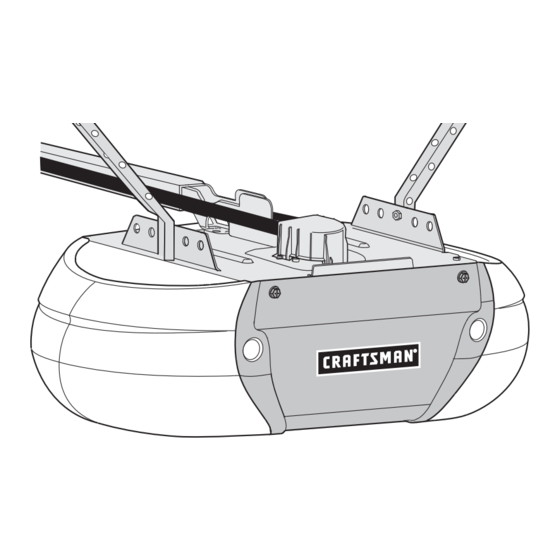
- Page 3 Owner’s Manual SMART CONTROL SMART GARAGE DOOR OPENER For Residential Use Only MODEL 139.57915 Read and follow all safety rules and operating instructions before first use of this product. Fasten the manual near the garage door after installation. Periodic checks of the opener are required to ensure safe operation.
-
Page 4: Table Of Contents
TABLE OF CONTENTS Adjustment 29-31 Introduction Introduction ........29 Safety symbol review and signal word review . -
Page 5: Introduction
INTRODUCTION Safety Symbol Review and Signal Word Review This garage door opener has been designed and tested to offer safe service provided it is installed, operated, maintained and tested in strict accordance with the instructions and warnings contained in this manual. When you see these Safety Symbols and Signal Words on the following pages, they will alert you to the possibility of serious injury or death if you do not comply with the warnings that... -
Page 6: Test The Wi-Fi ® Strength In Your Garage
® Check Signal Strength. If you see: Test the Wi-Fi Signal Strength in your garage You will need a router with Wi-Fi and a smartphone or other Wi-Fi signal is strong. You’re all set! mobile device. Make sure your mobile device is connected to your Install your new garage door opener. -
Page 7: Planning
Planning Identify the type and height of your garage door. Survey your Do you have an access door in addition to the garage door? If garage area to see if any of the conditions below apply to your not, Model 139.53702 Emergency Key Release is required. See installation. - Page 8 Planning (Continued) ONE-PIECE DOOR INSTALLATIONS Without a properly installed safety reversing sensor, persons Generally, a one-piece door does not require reinforcement. If (particularly small children) could be SERIOUSLY INJURED or your door is lightweight, refer to the information relating to KILLED by a closing garage door.
-
Page 9: Carton Inventory
Carton Inventory Your garage door opener is packaged in one carton which Hardware for assembly and installation is shown on the next contains the motor unit and all parts illustrated below. page. Save the carton and packing material until installation and Accessories will depend on the model purchased. -
Page 10: Hardware Inventory
Hardware Inventory Separate all hardware and group as shown below for the assembly and installation procedures. ASSEMBLY HARDWARE Lock Washer 3/8" Lock Nut Nut 3/8" Master Link 1/4"-20 Bolt 1/4"-20x1-3/4" Idler Bolt Threaded Shaft with Spring Trolley Nut INSTALLATION HARDWARE Carriage Bolt Handle Ring... -
Page 11: Assemble The Rail And Install The Trolley
ASSEMBLY STEP 1 Assemble the Rail and Install the Trolley To prevent INJURY from pinching, keep hands and fingers away To avoid installation difficulties, do not run the garage from the joints while assembling the rail. door opener until instructed to do so. The front rail has a cut out “window”... -
Page 12: Install The Idler Pulley
ASSEMBLY STEP 3 Install the Idler Pulley 1. Lay the belt beside the rail, as shown. Grasp the end with the hooked trolley connector and pass approximately 12" (30 cm) of belt through the window. Keep the ribbed side toward the rail, and allow it to hang until Assembly Step 4. -
Page 13: Install The Belt
ASSEMBLY STEP 4 HARDWARE SHOWN ACTUAL SIZE Install the Belt 1. Pull the belt around the idler pulley and toward the trolley. The ribbed side must contact the pulley. 2. Hook the trolley connector into the retaining slot on the Master Link trolley as shown (Figure 1). -
Page 14: Install The Sprocket Cover
ASSEMBLY STEP 6 Install the Sprocket Cover To avoid possible SERIOUS INJURY to finger from moving garage 1. Position the sprocket cover over the sprocket as shown and door opener: fasten to the mounting plate with 8x3/8" hex screws provided. ALWAYS keep hand clear of sprocket while operating opener. -
Page 15: Determine The Header Bracket Location
INSTALLATION STEP 1 Unfinished OPTIONAL Ceiling CEILING Determine the Header Bracket Location MOUNT HEADER BRACKET Header Wall To prevent possible SERIOUS INJURY or DEATH: Header bracket MUST be RIGIDLY fastened to structural Vertical Centerline of Garage Door support on header wall or ceiling, otherwise garage door might NOT reverse when required. -
Page 16: Install The Header Bracket
INSTALLATION STEP 2 HARDWARE SHOWN ACTUAL SIZE Install the Header Bracket You can attach the header bracket either to the wall above the garage door, or to the ceiling. Follow the instructions which will Lag Screw work best for your particular requirements. Do not install the 5/16"-9x1-5/8"... -
Page 17: Attach The Rail To The Header Bracket
INSTALLATION STEP 3 Attach the Rail to the Header Bracket 1. Position the opener on the garage floor below the header bracket. Use packing material as a protective base. NOTE: If the door spring is in the way, you will need help. Have someone hold the opener securely on a temporary support to allow the rail to clear the spring. -
Page 18: Position The Opener
INSTALLATION STEP 4 Position the Opener To prevent damage to garage door, rest garage door opener rail Follow instructions which apply to your door type as illustrated. on 2x4 placed on top section of door. SECTIONAL DOOR OR ONE-PIECE DOOR WITH TRACK Figure 1 A 2x4 laid flat is convenient for setting an ideal door-to-rail distance. -
Page 19: Hang The Opener
INSTALLATION STEP 5 Hang the Opener To avoid possible SERIOUS INJURY from a falling garage door Three representative installations are shown. Yours may be opener, fasten it SECURELY to structural supports of the garage. different. Hanging brackets should be angled (Figure 1) to provide Concrete anchors MUST be used if installing ANY brackets into rigid support. -
Page 20: Install The Lights
INSTALLATION STEP 6 Install the Lights To prevent possible OVERHEATING of the end panel or light 1. Press the release tabs on both sides of lens. Gently rotate socket: lens back and downward until the lens hinge is in the fully Use ONLY A19 incandescent (100W maximum) or compact open position. -
Page 21: Fasten The Door Bracket
INSTALLATION STEP 8 Fasten the Door Bracket Fiberglass, aluminum or lightweight steel garage doors WILL Follow instructions which apply to your door type as illustrated REQUIRE reinforcement BEFORE installation of door bracket. below or on the following page. Contact the garage door manufacturer or installing dealer for A horizontal reinforcement brace should be long enough to be opener reinforcement instructions or reinforcement kit. -
Page 22: Fasten The Door Bracket
Fasten the Door Bracket (Continued) ONE-PIECE DOORS Please read and comply with the warnings and reinforcement HARDWARE SHOWN instructions on the previous page. They apply to one-piece doors ACTUAL SIZE also. Center the door bracket on the top of the door, in line with the header bracket as shown. -
Page 23: Connect Door Arm To Trolley
Pulley INSTALLATION STEP 9 Figure 1 8" (20 cm) min. Connect Door Arm to Trolley Follow instructions which apply to your door type as illustrated below and on the following page. Inner Outer Trolley IMPORTANT: The groove on the straight door arm MUST face Trolley Ring away from the curved door arm (Figure 4). -
Page 24: Attach The Warning Labels
Figure 5 Connect Door Arm to Trolley (Continued) CORRECT INCORRECT ALL ONE-PIECE DOORS Straight IMPORTANT: The groove on the straight door arm MUST face Door Arm Straight away from the curved door arm (Figure 5). Door Arm Curved Curved 1. Close the door. Disconnect the trolley by pulling the (Groove Door Arm Door... -
Page 25: Install The Door Control
INSTALLATION STEP 11 Install the Door Control To prevent possible SERIOUS INJURY or DEATH from INTRODUCTION electrocution: NOTE: Older Craftsman door controls and third party products are Be sure power is NOT connected BEFORE installing door not compatible. Your garage door opener is compatible with up to 2 Smart Control panels. -
Page 26: Install The Protector System
INSTALLATION STEP 12 Install The Protector System ® Be sure power is NOT connected to the garage door opener BEFORE installing the safety reversing sensor. IMPORTANT INFORMATION ABOUT THE SAFETY REVERSING SENSORS To prevent SERIOUS INJURY or DEATH from closing garage The safety reversing sensors must be connected and aligned door: correctly before the garage door opener will move in the... - Page 27 Install The Protector System ® (Continued) Figure 1 DOOR TRACK MOUNT (RIGHT SIDE) INSTALLING THE BRACKETS Door Be sure power to the opener is disconnected. Install and align Track the brackets so the sensors will face each other across the garage door, with the beam no higher than 6"...
-
Page 28: Install The Protector System
Install The Protector System ® (Continued) Figure 5 Wing MOUNTING AND WIRING THE SAFETY REVERSING SENSORS Carriage Bolt Mounting: 1. Slide a 1/4"-20 x 1/2" carriage bolt head into the slot on each sensor. Use wing nuts to fasten sensors to brackets, with lenses pointing toward each other across the door. -
Page 29: Electrical Requirements
INSTALLATION STEP 13 Electrical Requirements To prevent possible SERIOUS INJURY or DEATH from To avoid installation difficulties, do not run the opener at electrocution or fire: this time. Be sure power is NOT connected to the opener, and To reduce the risk of electric shock, your garage door opener has disconnect power to circuit BEFORE removing cover to a grounding type plug with a third grounding pin. -
Page 30: Aligning The Safety Reversing Sensors
INSTALLATION STEP 14 Aligning the Safety Reversing Sensors Figure 1 The door will not close if the sensors have not been installed and aligned correctly. When the light beam is obstructed or misaligned while the door is closing, the door will reverse and the garage door opener lights will flash ten times. -
Page 31: Adjustment
ADJUSTMENT Introduction Your garage door opener is designed with electronic controls to make setup and adjustments easy. The adjustments allow you to Without a properly installed safety reversal system, persons program where the door will stop in the open (UP) and close (particularly small children) could be SERIOUSLY INJURED or (DOWN) position. -
Page 32: Program The Travel
ADJUSTMENT STEP 1 Program the Travel Without a properly installed safety reversal system, persons 1. Press and hold the (particularly small children) could be SERIOUSLY INJURED or Adjustment Button until the KILLED by a closing garage door. UP Button begins to flash Incorrect adjustment of garage door travel limits will and/or a beep is heard. -
Page 33: Test The Safety Reversal System
ADJUSTMENT STEP 2 Test the Safety Reversal System Without a properly installed safety reversal system, persons TEST (particularly small children) could be SERIOUSLY INJURED or KILLED by a closing garage door. 1. With the door fully open, place a 1-1/2 inch (3.8 cm) board (or a 2x4 laid flat) on the floor, centered under the garage door. -
Page 34: Smartphone Control
3. CONNECT THE GARAGE DOOR OPENER TO YOUR HOME SMARTPHONE CONTROL Wi-Fi NETWORK Get Connected Launch the web browser (such as Safari or Chrome) on your …and control your garage door opener with the Craftsman Garage mobile device and go to setupgdo.craftsman.com. Follow the on- Door app. -
Page 35: Operation
OPERATION IMPORTANT SAFETY INSTRUCTIONS To reduce the risk of SEVERE INJURY or DEATH: 1. READ AND FOLLOW ALL WARNINGS AND INSTRUCTIONS. 9. After ANY adjustments are made, the safety reversal system MUST be tested. 2. ALWAYS keep remote controls out of reach of children. 10. -
Page 36: Features
ENERGY CONSERVATION Features For energy efficiency the garage door opener will enter sleep Your garage door opener is equipped with features to provide you mode when the door is fully closed. The sleep mode shuts the with greater control over your garage door operation. garage door opener down until activated. -
Page 37: Door Control
Door Control LEARN A DEVICE SYNCHRONIZE THE DOOR CONTROL Any compatible remote controls, wireless keyless entry, or Smart To synchronize the door control to the garage door opener, press Control accessories can be programmed to the garage door the push bar until the garage door opener activates (it may take opener by pressing the LEARN button on the Motion-Detecting up to 3 presses). -
Page 38: Motion-Detecting Control Panel Setup
Motion-Detecting Control Panel Setup Motion Command LED Sensor NOTE: If the command LED is Switch continuously blinking, the Lock feature needs to be deactivated. Button LEARN Button LOCK Button Button HOLD OPEN Button 1 Minute, 5 Minute, and 10 Minute LIGHT Button TTC LED Motion... -
Page 39: Programming
Programming ® Your garage door opener has been programmed at the factory to operate with your remote control. Older Craftsman accessories are not compatible, see page 44 for compatible accessories. Programming can be done through the door control or the learn button on the garage door opener. -
Page 40: To Erase The Memory
To Erase the Memory ERASE ALL REMOTE CONTROLS AND KEYLESS ENTRIES ERASE THE CONNECTION FROM GARAGE DOOR OPENER TO HOME Wi-Fi NETWORK 1. Press and hold the LEARN button on garage door opener until the learn LED goes out (approximately 6 seconds). All remote 1. -
Page 41: To Open The Door Manually
To Open the Door Manually Trolley DISCONNECT THE TROLLEY To prevent possible SERIOUS INJURY or DEATH from a falling 1. The door should be fully closed if garage door: possible. If possible, use emergency release handle to disengage Trolley Release Arm 2. -
Page 42: Troubleshooting
TROUBLESHOOTING DIAGNOSTIC CHART Your garage door opener is programmed with self-diagnostic capabilities. The UP and DOWN arrows on the garage door opener flash the diagnostic codes. UP ARROW DOWN ARROW SYMPTOM SOLUTION FLASH(ES) FLASH(ES) The garage door opener will not Safety reversing sensors are not installed, connected, or wires close and the light bulbs flash. -
Page 43: Repair Protection Agreements
TROUBLESHOOTING UP ARROW DOWN ARROW SYMPTOM SOLUTION FLASH(ES) FLASH(ES) Opener runs approximately 6-8" Communication error to travel module. Check travel module (15-20 cm), stops and reverses. connections, replace travel module if necessary. The garage door opener will not Safety reversing sensors are misaligned or were momentarily close and the light bulbs flash. -
Page 44: Repair Parts
REPAIR PARTS Rail Assembly Parts PART DESCRIPTION 4A1008 Master link kit 041C5141-2 Complete trolley assembly 041A5665 Complete rail 41B4103 Spring trolley nut 144C54 Pulley kit 041A5250 Full belt assembly 041D0598-1 “U” bracket NOT SHOWN 183A163 Wear pads Installation Parts PART DESCRIPTION 041A7569 Premium Motion-Detecting Control Panel... -
Page 45: Motor Unit Assembly Parts
Motor Unit Assembly Parts PART PART DESCRIPTION DESCRIPTION 041C1751 Sprocket and Sprocket Cover 041D8916 Cover 041B4245-1 Line Cord 108D0077 Light Lens 041D8006-1 Motor with Travel Module 041C0279 Light Socket 041D8071-4 Travel Module 041A3150 Terminal Block 049DCTWF Receiver Logic Board 041D8234 Receiver Logic Board End Panel 041D8914 Front End Panel with All Labels... -
Page 46: Accessories
Accessories 139.53702 Emergency Key Release: 139.30498 Remote Control: Required for a garage with NO access door. Works with all Craftsman openers 1993- Enables homeowner to open garage door Present. Includes visor clip. manually from outside by disengaging trolley. 139.3050 Wireless Keypad: 139.53728 8 Foot (2.4 m) Rail Extension: For use outside of the home to enable access... -
Page 47: Repair Parts And Service
Product questions or problems? 1-888-331-4569 Customer Care Hot Line Get answers to questions, troubleshoot problems, order parts, or schedule repair service. Para respuestas a preguntas o problemas, y ordenar piezas o pedir servicio para la reparación de su equipo. To help us help you, register your product at www.craftsman.com/registration Para poderte ayudar mejor, registra tu producto en www.craftsman.com/registration Join the Craftsman Club today! Receive exclusive member benefits including special pricing and offers,...
Need help?
Do you have a question about the 139.57915 and is the answer not in the manual?
Questions and answers
Opener not working
What does the learn button look like on the opener?