Table of Contents
Advertisement
Advertisement
Table of Contents

Subscribe to Our Youtube Channel
Related Manuals for Leica Geosystems CS20

Summary of Contents for Leica Geosystems CS20
- Page 1 Leica CS20 & GS07 Sensors User Manual Version 1.0.2 English...
- Page 2 Bluetooth SIG, Inc. All other trademarks are the property of their respective owners. Validity of this This manual applies to the CS20 field controller, the GS07 and the CTR20/CGR4 manual expansion packs. Differences between the various models are marked and described.
- Page 3 Leica Geosystems On the last page of this manual, you can find the address of Leica Geosystems address book headquarters. For a list of regional contacts, please visit http://leica-geosystems.com/contact-us/sales_support. myWorld@Leica Geosystems (https://myworld.leica-geosystems.com) offers a wide range of services, information and training material.
-
Page 4: Table Of Contents
Data Storage Concept Container Contents CS Components GS07 Components User Interface Keyboard Operating Principles LED Indicators on CS20 LED Indicators on GS07 Operation Equipment Setup 4.1.1 Setting up as a Post-Processing Base 4.1.2 Fixing the Field Controller to a Holder and Pole 4.1.3... - Page 5 Technical Data CS20 GS07 6.2.1 Tracking Characteristics 6.2.2 Accuracy 6.2.3 Technical Data Conformity to National Regulations 6.3.1 Products without Radio 6.3.2 CS20 6.3.3 GS07, CTR20 6.3.4 CGR4 Software Licence Agreement Appendix A Pin Assignments and Sockets CS20 GS07 Table of Contents...
-
Page 6: Safety Directions
Safety Directions General Introduction Description The following directions enable the person responsible for the product, and the person who actually uses the equipment, to anticipate and avoid operational hazards. The person responsible for the product must ensure that all users understand these directions and adhere to them. -
Page 7: Definition Of Use
• Use of products with recognizable damages or defects. Use with accessories from other manufacturers without the prior explicit • approval of Leica Geosystems. Inadequate safeguards at the working site. • Controlling of machines, moving objects or similar monitoring application •... -
Page 8: Responsibilities
• To be familiar with local regulations relating to safety and accident preven- • tion. To inform Leica Geosystems immediately if the product and the application • becomes unsafe. • To ensure that the national laws, regulations and conditions for the opera- tion of the product are respected. - Page 9 WARNING Inadequate securing of the working site. This can lead to dangerous situations, for example in traffic, on building sites and at industrial installations. Precautions: ▶ Always ensure that the working site is adequately secured. ▶ Adhere to the regulations governing safety, accident prevention and road traffic.
- Page 10 DANGER Risk of being struck by lightning If the product is used with accessories, for example on masts, staffs, poles, you may increase the risk of being struck by lightning. Danger from high vol- tages also exists near power lines. Lightning, voltage peaks, or the touching of power lines can cause damage, injury and death.
- Page 11 Either of the following actions may cause you to receive an electric shock: Touching live components • Using the product after incorrect attempts were made to carry out repairs • Precautions: ▶ Do not open the product! ▶ Only Leica Geosystems authorised service centres are entitled to repair these products. Safety Directions...
-
Page 12: Laser Classification
WARNING Improperly repaired equipment Risk of injuries to users and equipment destruction due to lack of repair knowl- edge. Precautions: ▶ Only Leica Geosystems authorised service centres are entitled to repair these products. Laser Classification 1.6.1 General General The following chapters provide instructions and training information about laser safety according to international standard IEC 60825-1 (2014-05) and technical report IEC TR 60825-14 (2004-02). -
Page 13: Disto
1.6.2 DISTO General The DISTO module built into the product produces a visible red laser beam which emerges from the window at the top of the product. The laser product described in this section is classified as laser class 2 in accordance with: •... -
Page 14: Electromagnetic Compatibility Emc
WARNING Electromagnetic radiation can cause disturbances in other equipment. Although the product meets the strict regulations and standards which are in force in this respect, Leica Geosystems cannot completely exclude the possibil- ity that other equipment may be disturbed. CAUTION Use of the product with accessories from other manufacturers. -
Page 15: Fcc Statement, Applicable In U
Precautions: ▶ Although the product meets the strict regulations and standards which are in force in this respect, Leica Geosystems cannot completely exclude the possibility that other equipment can be disturbed or that humans or ani- mals can be affected. - Page 16 S.No.:1234567 Equip.No.:12345678 20XX Made in Switzerland, Manufactured: Leica Geosystems AG, CH-9435 Heerbrugg This device complies with part 15 of the FCC Rules. Operation is subject to the following two conditions: (1) This device may not cause harmful interference, and (2) this device must accept any interference received, including interference that may cause undesired operation.
- Page 17 / 2.8 Ah Made in China 15 A / 31.1 Wh Leica Geosystems AG, CH-9435 Heerbrugg This device complies with part 15 of the FCC Rules. Operation is subject to the following two conditions: (1) This device may not cause harmful interference, and...
-
Page 18: Description Of The System
Description of the System Overview System components CS20 GS07 CGR4 CTR20 CS20 3.75G CS20 3.75G CS20 CDMA DISTO DISTO 0016300_001 Terminology CS general descrip- CS is a collective term describing the various models of the multi-purpose field tion controller which is used with GNSS and TS instruments. -
Page 19: System Concept
Radios for remote control (RCS) or real-time kinematic (RTK) GNSS are available in the following variations: Type Description CS20 Radio unavailable CS20 with internal long-range Field controller with an integrated long-range TS communication radio TS communication radio. CS20 with expansion pack Field controller with an integrated long-range TS communication radio. - Page 20 Software for Description All CS models The software is stored in the flash RAM of the field controller. Firmware update instructions Download the most recent firmware file • from https://myworld.leica-geosystems.com. Copy the firmware file into the \SYSTEM • folder on the Leica SD card. ☞...
-
Page 21: Power Concept
Please note: Charging functionality is not available for CS20 field controller. CTR20, CGR4 Externally by the field controller. Please note: Expansion pack support is not available for CS20 field controller. GS07 Internally by GEB212 battery, OR Externally by GEV219 cable If an external power supply is connected and the internal battery is inserted, then the external power is used. -
Page 22: Container Contents
☞ While other SD cards can be used, Leica Geosystems recommends to only use Leica SD cards and is not responsible for data loss or any other error that can occur while using a non-Leica card. ☞ Removing the SD card or USB stick while the field controller is turned on can cause loss of data. - Page 23 GHT63 clamp Manuals and USB documentation card GEB212 or GEB331 batteries Antenna GAT18, GAT27 or GAT28 mobile antenna GAT21, GAT25 or GAT26 radio antenna Field controller with holder or CS35 tablet Tribrach Height hook USB stick Cables Antenna Stylus SD cards GAD34 arm 3 cm TNC QN-adapter Allen key and adjustment tool...
- Page 24 Container for GS instrument and accessories 0014955_001 Field controller with holder Antenna CRP15, quick release adaptor for quick mounting and demounting the GS18 to the pole without screwing GAT25, GAT26, GAT27 or GAT28 antenna Stylus GHT63 clamp USB stick GAT1 or GAT2 radio antennas Antenna arm microSD card including adapter or SD card Manual &...
-
Page 25: Cs Components
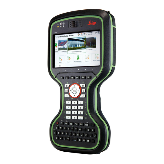
CS Components Upside of CS20 DISTO with camera Screen Keyboard Connector cover Power socket SD card slot USB A host port LEMO port (USB and serial) 008471_001 Underside of CS20 Hand strap Thread for screwing on hand strap or utility hook... -
Page 26: User Interface
User Interface Keyboard Keyboard display Function keys F1 - F6 Arrow keys Home Numeric keys ± key ON/OFF CAPS Lock Cameras Favourites ENTER Function keys F7 - F12; Backspace Alpha keys 008473_001 ENTER SPACE Keys Function Function keys Correspond to six softkeys that appear on F1-F6 the bottom of the screen when the screen is activated. - Page 27 Function ON/OFF If the field controller is already off: Turns the field controller on when held for 2 s. If the field controller is already on: • Turns to Power Options menu when held for 2 s. Turns the field controller off when held •...
-
Page 28: Operating Principles
The field controller has Light Emitting Diode indicators. They indicate the basic field controller status. Power LED Bluetooth LED Long range TS LED - not avail- able for CS20 field controller 008513_001 Description of the LEDs LED Status Status of Field Controller Power LED Power is off. -
Page 29: Led Indicators On Gs07
LED Status Status of Field Controller green Power is okay. flashing Power is okay. The battery is being charged. green Power is low. The remaining time for which enough power is available depends on the use of wireless modules, the temperature and the age of the battery. - Page 30 IF the THEN blue Bluetooth has connected. flashing blue Data is being transferred. GS07 PWR Power is off. green Power is 100% - 20%. Power is 20% - 5%. flashing red Power is low (<5%). The remaining time for which enough power is available depends on the type of survey, the temperature and the age of the battery.
-
Page 31: Operation
Operation Equipment Setup 4.1.1 Setting up as a Post-Processing Base The equipment setup described is used for static operations over markers. Description The instrument can be programmed with the field controller before use which can then be omitted from the setup. ☞... - Page 32 (micro)SD card GEB212 battery GRT146 carrier Tribrach Height hook Tripod GHT61 hand strap CompactFlash card Utility hook CS20 field controller GEB331 battery CS10/CS15 field controller GEB212 battery CS35 tablet USB stick Equipment setup Set up the tripod. step-by-step Mount and level the tribrach on the tripod.
-
Page 33: Fixing The Field Controller To A Holder And Pole
4.1.2 Fixing the Field Controller to a Holder and Pole Components of the The GHT66 holder consists of the following components: GHT66 holder GHT63 clamp Plastic sleeve Pole clamp Clamp bolt GHT66 holder Locking pin Top clip Mounting plate Bottom clip Tightening screw Mounting arm 008545_001... -
Page 34: Fixing A Hand Strap To The Cs
After the CS field controller is placed onto the mounting plate, ensure that the locking pin is put into the locked position. To lock the locking pin, push the locking pin to the right. 008549_001 Detaching the field Unlock the locking pin by pushing the locking pin to the left of the controller from a pole mounting plate. -
Page 35: Fixing The Utility Hook To The Cs
4.1.4 Fixing the Utility Hook to the CS Fixing the utility hook (GHT68) step-by-step 008498_001 ☞ If the hand strap is already attached to field controller, you need to detach it before you can fix the utility hook. ☞ Turn over the field controller. Place the screw of the utility hook into the thread at the top of the field controller and fasten it. -
Page 36: Inserting And Removing A Sim Card
SIM card step-by-step 5s = OFF 008506_001 ☞ Inserting/removing the SIM card while the CS20 is turned on can result in permanent damage to the card. Only insert/remove the SIM card when the CS20 is switched off. ☞ The SIM card is inserted into a slot inside the battery compartment. -
Page 37: Setting Up For Remote Control Or Rtk Using An Expansion Pack
4.1.7 Setting Up for Remote Control or RTK using an Expansion Pack Attaching the exten- This section does only apply to the models CS20 3.75G, CS20 3.75G DISTO and sion pack step-by- CS20 CDMA DISTO. step ☞... -
Page 38: Connecting To A Personal Computer
4.1.8 Connecting to a Personal Computer Description Windows Mobile Device Center for PCs with Windows 7/Windows 8/ Windows 10 operating system is the synchronization software for Windows mobile-based pocket PCs. WMDC enables a PC and a Windows mobile-based pocket PC to communicate. Leica USB drivers support Windows 7, Windows 8 (8.1) and Windows 10 oper- ating systems. - Page 39 Run the Setup_Leica_USB_XXbit.exe to install the drivers necessary for Leica devices. Depending on the version (32bit or 64bit) of the operating system on your PC, you have to select between the three setup files following: Setup_Leica_USB_32bit.exe • • Setup_Leica_USB_64bit.exe Setup_Leica_USB_64bit_itanium.exe •...
-
Page 40: Enabling Wlan In Windows Ec7
It is normal for the battery to become warm during charging. Using the • chargers recommended by Leica Geosystems, it is not possible to charge the battery once the temperature is too high. For new batteries or batteries that have been stored for a long time •... -
Page 41: Changing The Battery
Operation/discharging The batteries can be operated from -30°C to +60°C/-22°F to +140°F. • • Low operating temperatures reduce the capacity that can be drawn; high operating temperatures reduce the service life of the battery. 4.2.2 Changing the Battery Insert and remove the battery step-by-step 008509_001 ☞... -
Page 42: Charging The Battery
Close the battery compartment by pushing the slide fastener in the direction of the arrow with the close-lock symbol. 4.2.3 Charging the Battery Charge the battery ☞ Please note: Charging functionality is not available for CS20 field con- inside the CS20 step- troller (823 164). by-step GEV276 GEV219... -
Page 43: Power Functions
Refer to LED indicators for detailed information about the power LED. Charge battery for To charge the batteries for GS07, use the Leica Geosystems chargers GKL311 GS07 or GKL341. Refer to the GKL311 or GKL341 User Manual for further informa- tion. -
Page 44: Working With The Memory Device
Working with the Memory Device 4.4.1 Working with the SD Card ☞ • Keep the card dry. Use it only within the specified temperature range. • Do not bend the card. • Protect the card from direct impacts. • ☞ Failure to follow these instructions could result in data loss and/or permanent damage to the card. -
Page 45: Working With A Usb Memory Stick
4.4.2 Working with a USB Memory Stick Insert a USB stick step-by-step 008504_001 ☞ The USB stick can be inserted into a slot behind the connector cover. Push the slide fastener of the connector cover in the direction of the arrow with the open-lock symbol. -
Page 46: Using The Camera Flash Light As Torch
Using the Camera Flash Light as Torch Using the flash light You can use the flash light of the camera as torch. as torch To put the flash light on/off, hold and press Operation... -
Page 47: Care And Transport
Shipping When transporting the product by rail, air or sea, always use the complete orig- inal Leica Geosystems packaging, container and cardboard box, or its equiva- lent, to protect against shock and vibration. Shipping, transport of When transporting or shipping batteries, the person responsible for the prod-... - Page 48 Cables and plugs Keep plugs clean and dry. Blow away any dirt lodged in the plugs of the con- necting cables. Connectors with dust Wet connectors must be dry before attaching the dust cap. caps DISTO window 008590_001 Care and Transport...
-
Page 49: Technical Data
1600 x 1200 pixels, 2 MP Dimensions 150 mm 49 mm 008595_001 Weight Type Weight [kg]/[lbs] CS20 1.095/2.414 CS20 3.75G 1.175/2.590 CS20 3.75G/CDMA DISTO 1.215/2.678 Memory devices Data can be stored on the SD card, USB stick or in the internal memory. Technical Data... - Page 50 IP68 (IEC60529) Dust tight Protected against continuous immersion in water (tested for 2 hours in 1.40 m depth). ☞ CS20 is in compliance with IP68 only when expan- sion cover, connector cover and battery cover are closed. GEB331 IP54 (IEC 60529)
-
Page 51: Gs07
Parity: None Stop bits: Terminator: CR/LF Ports Type 8 pin LEMO-1 USB2.0 Host LEMO USB client (high-speed) CS20 For power and/or For communication communication GS07 6.2.1 Tracking Characteristics Satellite reception Multi-frequency Instrument channels ☞ Depending on the satellite systems and signals configured, a maxi- mum number of 320 channels is allocated. -
Page 52: Technical Data
☞ The measurement of accuracy is compliant with ISO 17123-8. Differential phase in Type Horizontal Vertical post-processing Static and rapid static 5 mm + 0.5 ppm 10 mm + 0.5 ppm Kinematic 10 mm + 1 ppm 20 mm + 1 ppm Static with long observations 3 mm + 0.5 ppm 6 mm + 0.5 ppm... -
Page 53: Conformity To National Regulations
For products without radio transmitter or receiver: national regulations FCC Part 15 (applicable in US) • Hereby, Leica Geosystems AG declares that the product/s • is/are in compliance with the essential requirements and other relevant provisions of the applicable European Direc- tives. -
Page 54: Cs20
• Hereby, Leica Geosystems AG declares that the radio equipment type CS20 is in compliance with Directive 2014/53/EU and other applicable European Directives. The full text of the EU declaration of conformity is available at the fol- lowing Internet address: http://www.leica-geosystems.com/ce. -
Page 55: Gs07, Ctr20
• national regulations • Hereby, Leica Geosystems AG declares that the radio equipment type GS07/CTR20 is in compliance with Directive 2014/53/EU and other appli- cable European Directives. The full text of the EU declaration of conformity is available at the fol- lowing Internet address: http://www.leica-geosystems.com/ce. -
Page 56: Cgr4
Conformity to FCC Part 15 (applicable in US) • national regulations Hereby, Leica Geosystems AG declares that the radio equipment type • CGR4 is in compliance with Directive 2014/53/EU and other applicable European Directives. The full text of the EU declaration of conformity is available at the fol- lowing Internet address: http://www.leica-geosystems.com/ce. -
Page 57: Software Licence Agreement
Leica Geosystems. Such software is protected by copyright and other laws and its use is defined and regulated by... -
Page 58: Appendix A Pin Assignments And Sockets
Appendix A Pin Assignments and Sockets CS20 Description Some applications require knowledge of the pin assignments for the instru- ment ports. In this chapter, the pin assignments and sockets for the instrument ports are explained. Ports at the instru- ment bottom panel -... - Page 59 Ports at the instru- ment underside Lemo port (USB and serial) 0016302_001 Pin assignments for 8 pin LEMO-1 PIN_001 Signal Name Function Direction USB_D+ USB data line In or out USB_D− USB data line In or out Signal ground RS232, receive data RS232, transmit data Not connected Power input, 10.5 V–28 V...
- Page 60 870196-1.0.2en Original text (870196-1.0.2en) Printed in Switzerland © 2018 Leica Geosystems AG, Heerbrugg, Switzerland Leica Geosystems AG Heinrich-Wild-Strasse CH-9435 Heerbrugg Switzerland Phone +41 71 727 31 31 www.leica-geosystems.com...
Need help?
Do you have a question about the CS20 and is the answer not in the manual?
Questions and answers