Table of Contents
Advertisement
Advertisement
Table of Contents

Summary of Contents for Tecno Automazione T011S
- Page 2 SAFETY INSTRUCTION This appliance can be used by children aged from 8 years and above and persons with reduced physical, sensory or mental capabilities or lack of experience and knowledge if they have been given supervision or instruction concerning use of the appliance in a safe way and understand the hazards involved.
-
Page 3: Table Of Contents
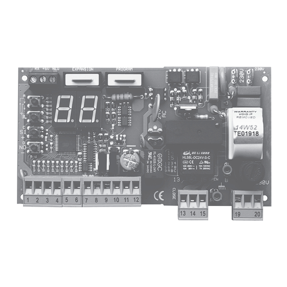
INDEX T011S ver. tS2112 ..................2 FUNCTIONS....................9 MENU NAVIGATION...................2 F0 AUTO-CLOSE TIME..............9 TROUBLE SHOOTING..................2 F1 PEDESTRIAN WORKING TIME..........9 STAND BY................3 F2 CLOSING KICK................9 - REMOTE TRANSMITTING..........3 F3 BLINKING TIME................9 STOP................3 F4 KICK BACK AT OPENING............9 tC / td EXTERNAL PHOTOCELL LOGIC 1/2.......3 F5 and F6 STANDARD, COMMUNITY MODE, STEP BY STEP ..9... - Page 4 T011S ver. tS2111 BOARD’S COMPONENTS Button A Button B Button C Button D 250 VAC power fuse 5A Resettable fuse 24V 1.6A Resettable fuse 24V 0.6A A B C Ground terminals Primary varistor Secondary varistor Terminal block pins 1 to 20 Button A...
-
Page 5: Menu Navigation
MENU NAVIGATION DISPLAY REPORT DISPLAY DESCRIPTION STAND BY The control board is waiting for a command. REMOTE TRANSMITTING A remote key is pressed. The display showing a dot. Stop input open ( Terminal block 2 Normally closed, STOP Stop remote key pressed, stored using function. - Page 6 INSTALLING RADIO MODULE You can choose to install the radio module inside the flashing lamp or antenna to increase the signal range. FLASHING LAMP BASE RADIO-ANTENNA HOUSING Screws and stops not included. 3.5mm. x 13mm. COVER 3.5mm. x 13mm. LIGTHS 3.5 mm.
-
Page 7: Ta Internal Photocell
CONNECTIONS Go, OPEN oP, CLOSE CL, START A1..A9 MOTOR DEAD-MAN OPEN Po, no, STOP 5t, DISABLED POWER SUPPLY 230 VAC DEAD-MAN CLOSE PC, DOMUS Eo, OPEN oP, CLOSE CL ELECTRIC-LOCK EL 13: CLOSE 14: COMMON 15: OPEN FLASHING LAMP PE, OPEN oP, PEDESTRIAN . - Page 8 GLOSSARY The gate is completely closed and the stop, the external photocells, the internal photocells and the STAND BY opening limit switch are not activated. The control board is ready to start a working cycle. In this state the flashing lamp is off. The gate is opening and the flashing lamp blinks quickly (0.3 seconds ON and 0.2 seconds OFF).
-
Page 9: Www.tecnoautomazione.com
MOTOR The opening and closing cycles are subdivided into two phases: The standard phase STANDARD WORKING A1 and the slowdown phase A2. TIME Programs the duration of the standard phase, during this time the force of the motor is A5. →... -
Page 10: Www.tecnoautomazione.com
SENSOR OPERATING MODE There are two sensor operating modes: Obstacle Detection and Limit switch. They are described in the table below: OBSTACLE DETECTION LIMIT SWITCH In this operating mode the motor changes direction. If the direction was In this operating mode the motor finishes the closure, the gate opens completely. -
Page 11: Typical Installation
FUNCTIONS The gate remains open for seconds at the end of opening before begging the closing phase. AUTO-CLOSE TIME To disable hold down @C button until display shows It is the motor working time during a pedestrian working cycle. The slowdown phase is skipped during the PEDESTRIAN WORKING TIME opening and executed during the closing. -
Page 12: Opening
FUNCTIONS L4 = SI → ENABLED L4 = no → DISABLED SAFETY BY PASS L4 allows to open/close the gate even if stop or photocells inputs are detected (I.E. damaged FUNCTION photocells). It requires a normally open push button wired on the terminal block 1-8 or 7-8. E1 / E7 must be set to one of following functions: Go start, oP open, CL close. - Page 13 PRE-PROGRAMMED CONFIGURATIONS Keep pressing button A or B until the display shows . The control board shows FACTORY CONFIGURATION . To set the factory settings hold down button C until the display shows . The factory configuration does not have any effect on radio memory. MOTOR TERMINAL BLOCK FUNCTIONS...
-
Page 14: Standard Working Cycle
REMOTE Keep pressing A or B button until the display shows r0. After a few seconds the control SINGLE ERASE board starts scanning for stored codes. Each code showed is a remote key ID. To erase hold down button C. The display blinks showing remote key ID. When the display is off the remote key ID has been erased. -
Page 15: Functions
INPUTS Each terminal block is programmable by a configuration parameter. E1 → input 1, E2 → input 2 , E3 → input 3, E4 → input 4, E5 → input 5, E6 → input 6, and E7 → input 7 FUNCTIONS DESCRIPITION TYPE... -
Page 16: Test
PROGRAMMING PROCEDURE MOTOR YOU NEED: START Button WORKING TIME • For saving a remote key as START, using buttons A/B to select r1. hold down the remote key PROGRAMMING then press button C on the control board. Check the motor direction. •... - Page 17 PROGRAMMING OBSTACLE SENSOR P6 helps you to program the obstacle detection sensor. OBSTACLE PROGRAMMING P6 sets: A7 → Motor A standard obstacle detection threshold • A8 → Motor A slowdown obstacle detection threshold • HOW-TO: The gate must be closed. Selecting P6 using buttons A/B.
-
Page 18: Terminal Block Inputs
INTRODUCTION DOMUS MODULE The DOMUS expansion consists of a DOMUS MODULE and up to three RELAY MODULES. The DOMUS module expands the control board with three open collector outputs. Each output controls a relay module. The DOMUS module has a push-button K1 to select the outputs menu and three LEDs: L1, L2 and L3. -
Page 19: Recycle
RECYCLE For private households: Information on Disposal for Users of WEEE This symbol on the product(s) and / or accompanying documents means that used electrical and electronic equipment (WEEE) should not be mixed with general household waste. For proper treatment, recovery and recycling, please take this product(s) to designated collection points where it will be accepted free of charge.
Need help?
Do you have a question about the T011S and is the answer not in the manual?
Questions and answers