Table of Contents
Advertisement
Quick Links
IMPORTANT INSTRUCTIONS - SAVE THESE INSTRUCTIONS
Read all instructions before installing or using the heater. Please adhere to instructions published in this manual.
Failure to do so may be dangerous and may void certain provisions of your warranty.
Gas Fired Railway Switch Heater
HELLFIRE 900
Installation, Operation, & Maintenance Instructions
ANSI Z83.7-2017 / CSA 2.14-2017
Gas Fired Unvented Construction Heaters (Unattended Type)
Fastrax
is a registered trademark of Thermon Heating Systems, Inc.
®
Copyright
2018. All rights reserved.
©
Part No. HF18948.Rev.3.04
November 2018
ISO 9001
Printed in Canada
Advertisement
Table of Contents

Summary of Contents for Fastrax Hellfire 900
- Page 1 Failure to do so may be dangerous and may void certain provisions of your warranty. ISO 9001 Gas Fired Railway Switch Heater HELLFIRE 900 Installation, Operation, & Maintenance Instructions ANSI Z83.7-2017 / CSA 2.14-2017 Gas Fired Unvented Construction Heaters (Unattended Type) Fastrax is a registered trademark of Thermon Heating Systems, Inc.
-
Page 2: Table Of Contents
TABLE OF CONTENTS E.18 Reset ..............18 A. Important Notices And Warning Symbols E.19 Energy Management System (EMS) .....19 B. Identification E.20 Terminal Blocks ...........20 Heater Labels ............6 E.21 Inputs and Outputs ..........20 Model and Serial Number Tag .......6 F. Troubleshooting Components Diagram ...........6 Control Panel Diagram - 240V Single Phase G. - Page 3 J. Service Recommended Service Schedule ......45 Gas Supply Pressure ...........46 Gas Supply Leak Test ..........46 Manifold Leak Test ..........46 Main And Safety Gas Solenoid Valves Leak Test .47 Dirt Trap And Strainer ..........47 Motor ..............47 Vibration Specifications and Measurement ..47 Lubrication ............47 J.10 Flame Safety Relay (FSR)........47...
-
Page 4: Important Notices And Warning Symbols
IMPORTANT NOTICES AND WARNING SYMBOLS Keep this manual with the machine at all times. The purpose of WARNING. Read and adhere to the following. FAILURE this manual is to provide owners, operators, and installers with TO DO SO MAY RESULT IN SEVERE OR FATAL the precautions and procedures essential for the safe and proper INJURY. - Page 5 Description Symbol English French If you smell gas; immediately extinguish all sources of S’il y a une odeur de gaz : fermer immédiatement toute ignition and turn off gas source. Call qualified service source d’allumage et de gaz. Faire réparer la fuite par un technician to repair leak.
-
Page 6: Identification
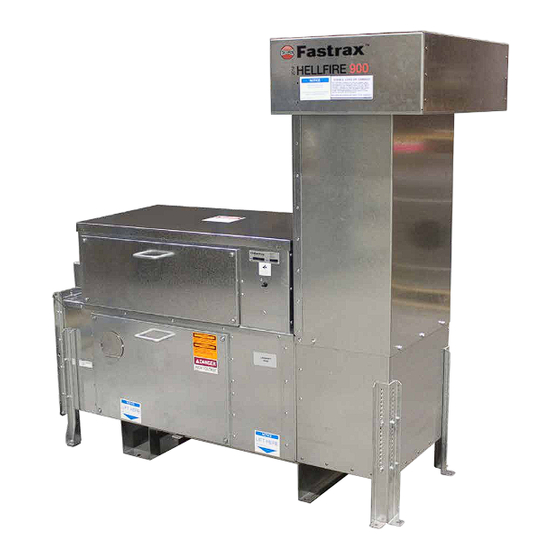
IDENTIFICATION The logo, located on the side of the air intake hood Heater Labels identifies the series as HELLFIRE, and the size, either 400 Each heater has a ratings label, a logo label, a model and or 900. serial number tag and a voltage label. The model / serial number tag is a blue aluminum plate. -
Page 7: Control Panel Diagram - 240V Single Phase Example Shown
Control Panel Diagram - 240V Single Phase Example Shown No. Label No. Label Track duct Air intake plenum Track duct elbow Leveling leg Rail mounting spring clip and pad Control panel Ballast retainer Motor/Impeller/Base Thermostat box Combustion chamber access panel Precipitation detector Transition duct Burner... -
Page 8: Pre-Operation Inspection
PRE-OPERATION INSPECTION Label Label Regulator vent Manifold gas pressure gage Regulator vent pipe Main manual shutoff valve Pilot gas solenoid valve Union Pilot gas pressure regulator Burner mounting bracket Pilot manual shutoff valve Burner defroster Gas supply inlet Igniter Gas supply pressure gage Flame rod Main gas pressure regulator Burner... -
Page 9: Important Notices
Important Notices To ensure trouble free operation during the winter months, inspect NOTE: Perform inspection and operations in accordance with WARNING. All persons employed in handling propane the system annually at the start of the season. the instructions provided in the service section of this or natural gas shall be trained in proper handling and manual. - Page 10 Inspect Action Verify correct line voltages at each heater. Must be within +/- 5% of nominal voltage. Electrical supply Verify current draw is less than or equal to nameplate rating. Verify supply and manifold gas pressures are within nameplate limits when heater and all Gas supply connected loads are operating.
-
Page 11: Operation
If the heater is in ‘REMOTE SCADA’ mode and the to maintain the rail temperature. ‘Fastrax® RCMS’ software is requesting performance REMOTE SCADA - With the controller configured for operation, the burner will remain lit regardless of rail REMOTE SCADA MODE, toggling the mode selector thermostat status. - Page 12 The factory default setting is 550,000 BTU/hr when WARNING. Install cap once regulator adjustment is operated on LPG, or 390,000 BTU/hr on NG. complete. In the event of pressure relief, the cap must The heat output can be adjusted as follows: be closed to vent gas to the exterior.
-
Page 13: Controls & Indications
NOTE: Controllers are not interchangeable between HELLFIRE connections are made with plug connectors to allow quick 400 (24V AC) and HELLFIRE 900 (120V AC). replacement in the event of a failure. With the addition of the EMS package, a stand alone heater can operate automatically based on weather... -
Page 14: Controls
On the controller are a number of status LEDs intended NOTE: This setting is overridden when operated in REMOTE to aid the user’s understanding of the heater state of SCADA mode by the corresponding Fastrax® RCMS operation. See Table 6 - Controller LED Descriptions for software parameter. full description. -
Page 15: Terminal Blocks
LED Name Description State Indication EMS module request for heater to run. EMS REQ EMS request Heater only acts on this request if in AUTO mode. POWER Power supply Controller energized. MOTOR Motor Contactor closed, motor turned on. Controller HEAT FSR requested. -
Page 16: Data Communications
Data Communications Activating a COMMUNICATION Parameter The RS-485 serial communications port, and an NOTE: Read and understand the following procedure before EEPROM, allows the heater to be part of a Supervisory starting. COMMUNICATION parameters require a Control and Data Acquisition (SCADA) network and hardware programming key to make changes, MODE Remote Control and Monitoring System (RCMS) software. -
Page 17: Activating Mode Parameter
E.10 Activating MODE Parameter E.14 RAIL THERMOSTAT Mode, Reverse NOTE: Read and understand the following procedure before When enabled, the controller is configured to operate starting. with the previous, open on rise (OOR), thermostat. The controller must be powered on for a minimum of 60 seconds, the mode selector switch toggled OFF, and E.15 Failure Shutdowns and Alarm Indications... -
Page 18: Aggressive Retry Feature
Table 10 – Fault Condition Codes and LED States E.18 Reset Prior to performing a reset: Alarm Code Fault Condition State Type WARNING. If you smell gas; Immediately extinguish all Selector switch left in sources of ignition and turn off gas source. Minor OFF position for more ENABLE... -
Page 19: Energy Management System (Ems)
TEST switch. EMS request to turn HEAT ON Heater request These setting are overridden when operated in REMOTE on heater. SCADA mode by the corresponding Fastrax® RCMS Ambient software parameter. temperature is below set point. SNOW-RAIN: Low Temperature... -
Page 20: Terminal Blocks
E.20 Terminal Blocks E.21 Inputs and Outputs The controller interconnects with the control panel by PRECIPITATION DETECTOR: As its name implies, it means of 2 board level headers, TB-1 and TB-2, which senses precipitation that can be in the form of rain or accept wire harness plug connectors. -
Page 21: Troubleshooting
TROUBLESHOOTING * The resets made by aggressive retry function are not described in the **Reset controller only after observing the condition of all status indicators conditions. then follow reset instructions. Problem Conditions* Possible Cause Remedy** • Verify panel and motor breakers are closed. No LEDs are on. - Page 22 Problem Conditions* Possible Cause Remedy** The as delivered heater is set for LPG operation. Manifold pressure at Heater connected to natural gas. Increase manifold pressure to within natural gas maximum for propane. limits. • Service burner. Heater operating Corrosion, dirt or other debris Manifold pressure at •...
- Page 23 Problem Conditions* Possible Cause Remedy** • Fan starts, runs briefly Heater NOT connected to duct Complete heater installation. then stops. system. • Controller LEDs Clear intake screen of blockage, Air intake severely blocked. – POWER on. i.e. ice, snow, paper. –...
- Page 24 Problem Conditions* Possible Cause Remedy** Marginal flame signal. • Inspect flame rod and wiring. • Fan starts. • Replace any damaged items, fouled rod, PILOT signal above and MAIN signal below 1.2 micro amps. corroded wire or cracked boot. • Controller LEDs –...
-
Page 25: Installation
INSTALLATION Overview WARNING. Install and use Heater in accordance with owners manual and local codes. The following are general guidelines for the installation of typical WARNING HELLFIRE gas fired systems. They should be followed in In the absence of local codes, installation must comply with CAN/CSA-B149 Installation code and National Fuel conjunction with the specific site layout drawings provided with Gas Code ANSI Z223.1 / NFPA 54, or Standard for the... - Page 26 Figure 2 – 140” Clearance Figure 3 – 155” Clearance 26 26...
- Page 27 Figure 4 – 155” Clearance Turned 90 Degrees...
-
Page 28: Site Preparation
Site Preparation Identify the tie to be replaced by the tie duct, or the crib for the crib ducts. Relative to the appropriate tie or crib, prepare a foundation for the heater with ties, concrete pad, or other suitable level mounting structure. Note the location for the gas, electrical supply, and the signal cable lines. -
Page 29: Power Connections
entrance panel and main disconnect. Observe primary surge Three Phase Systems Only protector manufacturer’s instructions for installation and circuit breaker protection (if required). CAUTION. For three phase systems only - verify correct fan rotation. • Grounding of the switch heater metal housing as well as CAUTION the ground terminals of the primary arresters is essential for personnel protection as well as surge protection. - Page 30 Conductor Sizing Using the following table to aid in the selection of the appropriate size conductors between the heater and service. Table 13 – Conductor Sizing Wire Size Maximum Distance 1131 1799 2860 1289 2048 3257 1579 5179 1681 2675 1296 4250 2060...
-
Page 31: Thermostat Installation
Thermostat Installation Install the thermostat sensor box as per instructions below: Remove combustion chamber shipping cover. Detach thermostat box from shipping cover. Secure thermostats to the duct using SST machine screws - ensure colour coded wires match. Secure thermostat box to the sensor duct as depicted, with the ground wire under the head of a bolt and washers. - Page 32 Ambient Temperature Sensor Precipitation Indicator To route the sensor cable it is necessary to remove the air Remove the plug from the top hole marked ‘Precipitation intake. Sensor’. Pass the 4-pin connector through the hole, install lock nut and tighten. Remove the 4 screws holding the extension to the elbow.
- Page 33 Rail Thermostat Pass the two (2) wires from the rail temperature sensor through the hole, install the locknut and Mount the rail thermostat on the field or gage side of tighten. the stock rail ahead of the points and tie duct, as shown. Select a location shaded from the sun.
-
Page 34: Inspection And Commissioning
G.11 Inspection and Commissioning Gas System Supply pressure at rated supply pressure with all … Once the installation is complete review it against the following connected loads operating. checklist. Gas supply leak tested. … Point Nozzles Heater Installed. … Level. …... -
Page 35: Heater Specifications
HEATER SPECIFICATIONS Performance Controls Table 17 – Controls • Clears ice and snow from switches with up to 40-foot points or longer. (Recommended heating, 10,000 to 22,500 BTU/hr per Feature Description foot of track coverage, based on severity of local climate). V AC Provide dry contract, rated for 24 Remote Start... -
Page 36: Controller Terminal Identification
Controller Terminal Identification Table 19 – Controller Terminal Identification Terminal Block Input Output Power Source V AC Neutral Motor Contactor V AC Neutral V AC Transformer Neutral V AC V AC V AC FSR Request V AC V AC From Transformer V AC V AC From Transformer Run Indication Dry Relay Contact Run Indication Dry Relay Contact Alarm Indication... -
Page 37: Schematicsmaintenance
SchematicsMaintenance... - Page 41 41 41...
- Page 42 42 42...
-
Page 43: Maintenance
MAINTENANCE Thermostat Removal Remove cover from thermostat box to gain access to the thermostats. There are two thermostats. The high limit, which has a red and a white wire connected to it, and the cycling thermostat, which has a black and a blue wire, connected to it. -
Page 44: Flame Rod And Spark Igniter Removal
Flame Rod and Spark Igniter Removal Burner Defroster Removal NOTE: The defroster circuit is protected with a reset-enabled fuse. If tripped, open then close the panel breaker to reset. Turn heater OFF and disconnect power. If the flame rod (16) or spark igniter (15) requires inspection or replacement, remove them as follows: Once impeller is at a complete stand still, remove combustion chamber access panel. -
Page 45: Service
SERVICE WARNING. Burn hazard / hot surfaces. Do not touch WARNING. Install and use Heater in accordance with owners manual and local codes. track ducts, nozzles or any non-insulated duct connected downstream of heater during operation WARNING WARNING In the absence of local codes, installation must comply with CAN/CSA-B149 Installation code and National Fuel Gas Code ANSI Z223.1 / NFPA 54, or Standard for the WARNING. -
Page 46: Gas Supply Pressure
Inspect heater annually. testing solution. If a gas leak is detected, replace any cracked fittings or components, tighten any leaking pipe Ensure the air intake and all ductwork are not obstructed. connection, or disassemble, reapply pipe thread sealant, Keep area around heater clear and free from combustible and reassemble. -
Page 47: Main And Safety Gas Solenoid Valves Leak Test
Main And Safety Gas Solenoid Valves Leak Test Vibration Specifications and Measurement Turn heater OFF. All motor/impeller/base sets are match balanced with vibration levels lower than 0.20 in./sec RMS, at the four Verify supply pressure is between 5 – 20 psi. points depicted. -
Page 48: Flame Signal
As a further check, close the manual gas valve. The Remove the blockage and reset the controller. The heater FLAME LED goes out, followed by the MAIN and PILOT starts. LED, the red ALARM LED lights. Open manual gas valves. Reset controller, which in turn resets FSR. -
Page 49: Aar Terminals, Signals, And Communications
J.15 AAR Terminals, Signals, and Communications To correct the problem, remove the burner, flame rod and igniter, following the removal instructions in the To verify remote start: maintenance section. Place the heater in REMOTE RTC mode, and make Drill out any blocked gas orifice using a #47 (.0785) drill bit. a contact closure across AAR terminals A1 A2. -
Page 50: Parts
PARTS Parts - Heater Body Table 20 – Heater Body Parts List Index Part No. Description Index Part No. Description 18929 LID, ELECTRICAL COMPARTMENT 17439-XX MOT/IMPLR ASSY 17437-01 LOCKING BAR, TOP HF900 240V AC 1PH 16058 PLENUM, INTAKE, HF900 HF900 208/230/460V AC 3PH 16075 LEG, REAR, HF400/900 HF900 575V AC 3PH 16067-01 EXT, INTAKE W/SCREEN, 13”L HF900... -
Page 51: Parts - Control Panel, 240V Single Phase
Parts - Control Panel, 240V Single Phase Table 21 – Control Panel Parts List Index Part No. Description Index Part No. Description 9012-0059 BUCHANAN TSB100012DS=TUBULAR BARRIER ST 9078-0043 CONTACTOR, 2 POLE, 25A, 120V COIL 9040-0018 RELAY, FS, BURNER CONTROL 9078-0044 PROTECTIVE COVER, CONTACTOR,2 POLE 9040-0022 AMPLIFIER, FS, MDL 9079-0004 RCPT, DUPLEX 15A-125V, GFCI SMARTLOCK 9040-0023 CARD, FS, PURGE TIMER, 2 SEC... -
Page 52: Parts - Control Panel, 460V/575V Three Phase With 120V Duplex Receptacle
Table 23 – Control Panel Parts List Index Part No. Description Index Part No. Description 9012-0059 BUCHANAN TSB100012DS=TUBULAR BARRIER ST 9077-0033 FUSE, RESETTABLE 9040-0018 RELAY, FS, BURNER CONTROL 9077-0034 CB, 1A, PNL MNT 9040-0022 AMPLIFIER, FS, MDL 9078-0126 CONTACTOR, 12A C/W 120V COIL 9040-0023 CARD, FS, PURGE TIMER, 2 SEC 18532 LABEL, AAR CONNECTOR, VINYL 18783-02 CONTROLLER, 900 HEATER... - Page 53 1,16 Table 25 – Parts - Gas Components Index Part No. Description Index Part No. Description 19304 HTR, 2”DIA 30W 24V AC 18”L LEADS SI 16952 PILOT REGULATOR, MODIFIED 9045-0085 CONN, 1/4TUBE MALE * 1/8NPTM, BR SPRING WEDGE, 2”X2”, SST,HF900 BURNER 17927 9045-0160 VALVE, BALL 1/4”...
- Page 54 NOTES...
- Page 55 NOTES...
- Page 56 • 12 months - HELLFIRE Heaters, FEB Heaters the terms and conditions of the contract. • 12 months - All other Fastrax Products ® The Purchaser agrees that the Company makes no warranty or guarantee, express, implied or statutory, (including any warranty...
Need help?
Do you have a question about the Hellfire 900 and is the answer not in the manual?
Questions and answers