Advertisement
Project Documentation | Getting Started Guide for Automotive and Industrial
Radar Sensors
Project Number:
...
SMS Project Number:
...
Project Title:
...
Keyword(s):
...
Date:
January 30, 2019
Document:
Getting_started_Guide.docx
Document state:
In progress
Ready for review
X
Released
Outdated
CONFIDENTIAL AND PROPRIETARY
The Information contained in this document shall remain the sole exclusive property of s.m.s smart microwave sensors GmbH and shall not
be disclosed by the recipient to third parties without prior consent of s.m.s smart microwave sensors GmbH in writing.
Getting_started_Guide I Page 1 of 16 I January 30, 2019
Advertisement
Table of Contents

Related Manuals for smartmicro UMRR-11 T132

Summary of Contents for smartmicro UMRR-11 T132
- Page 1 Project Documentation | Getting Started Guide for Automotive and Industrial Radar Sensors Project Number: SMS Project Number: Project Title: Keyword(s): Date: January 30, 2019 Document: Getting_started_Guide.docx Document state: In progress Ready for review Released Outdated CONFIDENTIAL AND PROPRIETARY The Information contained in this document shall remain the sole exclusive property of s.m.s smart microwave sensors GmbH and shall not be disclosed by the recipient to third parties without prior consent of s.m.s smart microwave sensors GmbH in writing.
-
Page 2: Table Of Contents
1 Contents Contents ........................2 Reference Documents ....................3 Getting Started ......................4 Hardware UMRR-11 T132 ..................4 Hardware UMRR-8F T146 ..................6 Installation of the sensors ..................8 3.3.1 UMRR-11 T132 ....................8 3.3.2 UMRR-8F T146 ....................9 DriveRecorder3 software ..................10 3.4.1... -
Page 3: Reference Documents
Reference Documents Document SVN-ID Notes UMRR_Automotive_Ty pe_132_Data_Sheet.p UMRR_Automotive_Ty pe_146_Data_Sheet.p Datasheet_DR3.pdf Detailed_Feature_List _DR3.pdf CustomerInterface Table 1: Reference documents CONFIDENTIAL AND PROPRIETARY The Information contained in this document shall remain the sole exclusive property of s.m.s smart microwave sensors GmbH and shall not be disclosed by the recipient to third parties without prior consent of s.m.s smart microwave sensors GmbH in writing. -
Page 4: Getting Started
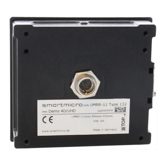
3 Getting Started 3.1 Hardware UMRR-11 T132 Picture 1: UMRR-11 Type 132 (1) with CABLE-0C0200 (2) and BRACKET-030400 (3, optional, different models available) CONFIDENTIAL AND PROPRIETARY The Information contained in this document shall remain the sole exclusive property of s.m.s smart microwave sensors GmbH and shall not be disclosed by the recipient to third parties without prior consent of s.m.s smart microwave sensors GmbH in writing. - Page 5 Picture 2: Connecting UMRR-11 Type 132 to the cable The sensor has to be connected with a bayonet connector to the cable (1) as seen in Picture 2. Afterwards, the connection to the CAN interface is established by the DSUB9-connector labeled “CAN”...
-
Page 6: Hardware Umrr-8F T146
3.2 Hardware UMRR-8F T146 Picture 3: UMRR-8F Type 146 (1) with compatible CABLE-FF0025 (2) CONFIDENTIAL AND PROPRIETARY The Information contained in this document shall remain the sole exclusive property of s.m.s smart microwave sensors GmbH and shall not be disclosed by the recipient to third parties without prior consent of s.m.s smart microwave sensors GmbH in writing. Getting_started_Guide I Page 6 of 16 I January 30, 2019... - Page 7 Picture 4: Connecting UMRR-8F Type 146 to the cable To operate the UMRR-8F Type 146 the sensor has to be connected to the cable as shown in Picture 4, Number 1. The connection to the CAN interface is established by the DSUB9- connector labeled with “CAN”...
-
Page 8: Installation Of The Sensors
Picture 5: Coordinate system relative to UMRR-11 T132 CONFIDENTIAL AND PROPRIETARY The Information contained in this document shall remain the sole exclusive property of s.m.s smart microwave sensors GmbH and shall not be disclosed by the recipient to third parties without prior consent of s.m.s smart microwave sensors GmbH in writing. -
Page 9: Umrr-8F T146
3.3.2 UMRR-8F T146 The connector of the UMRR-8F has to show to the left side (see Picture 6) if you’re looking from behind. The origin of the coordinate system is in the middle of the sensor (zero axis). The azimuth angle refers to the horizontal axis, whereas the elevation angle refers to the vertical axis as indicated in Picture 6. -
Page 10: Driverecorder3 Software
The DriveRecorder3 (DR3) is a smartmicro tool for visualization, recording, replaying and exporting of CAN or Ethernet data. This software can be downloaded on smartmicro’s homepage. For using the DR3 an access code is required. When starting the DR3 for the first time after installation, a request code will be generated. -
Page 11: Driverecorder3
1 2 3 Picture 8: Controller with active monitoring The CAN raw data (not interpreted data) is displayed in the CANdataGrid. In this window the messages are sorted either by identifier (= identifier mode -> so each message with the same identifier overwrites the old message with this same identifier) or sorted by time (= buffer mode). -
Page 12: Using Desktop Files
3.4.3 Using Desktop files The behavior of the DR3 is mainly controlled by the so called “desktops”, which store the configuration within a *.dsk file. There are three DR3 desktops delivered within the installation of the software, one for UMRR-8F Type 146 and two for the UMRR-11 Type 132. To load the appropriate desktop, open the “File”... - Page 13 Picture 12: Sensor Drawing Settings Picture 11: TargetDraw settings Afterwards a click on the field “Sensor drawing settings” (1 in Picture 11) should make a button appear next to “Collection”, which, once clicked, opens the dialogue shown in Picture 12. At the bottom there is the option to turn the velocity vector on (or off). Another noticeable option within the TargetDraw is the configuration of reference lanes.
- Page 14 for different applications or scenarios is possible. This is true for every configuration dialogue within DR3. Picture 13: Automotive settings CONFIDENTIAL AND PROPRIETARY The Information contained in this document shall remain the sole exclusive property of s.m.s smart microwave sensors GmbH and shall not be disclosed by the recipient to third parties without prior consent of s.m.s smart microwave sensors GmbH in writing.
-
Page 15: Important Legal Disclaimer Notice
Product. To the extent permitted by applicable law, Smartmicro disclaims (i) any and all liability arising out of the application or use of the Product or the data contained herein, (ii) any and all liability of damages exceeding direct damages, including - without limitation – indirect, consequential or incidental damages, and (iii) any and all implied warranties, including warranties of suitability of the Product for a particular purpose. -
Page 16: Contact
Phone: +49-531-39023-0 Fax: +49-531-39023-599 Web / Email address: Web: www.smartmicro.de Email: info@smartmicro.de Technical support for industrial and automotive sensors: support@smartmicro.de CONFIDENTIAL AND PROPRIETARY The Information contained in this document shall remain the sole exclusive property of s.m.s smart microwave sensors GmbH and shall not be disclosed by the recipient to third parties without prior consent of s.m.s smart microwave sensors GmbH in writing.
Need help?
Do you have a question about the UMRR-11 T132 and is the answer not in the manual?
Questions and answers