Table of Contents
Advertisement
Quick Links
Advertisement
Table of Contents

Summary of Contents for Bosch Motorsport DDU 7
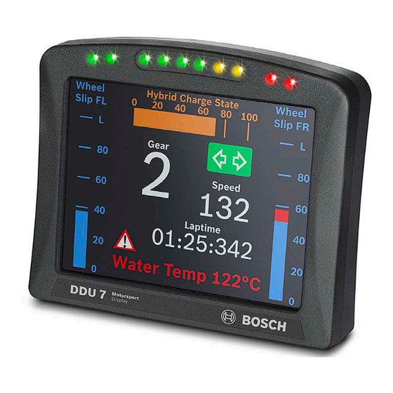
- Page 1 Bosch Motorsport Display DDU 7 Manual F 02U 003 052-01...
-
Page 3: Table Of Contents
5.2 Output channels ....................10 5.3 Communication channels ..................11 5.4 Pin layout connector ....................12 6 Mechanical drawing ..................... 13 7 Starting up the DDU 7 ..................14 7.1 Before starting ....................... 14 7.2 Feature activation ....................21 7.3 1 display configuration (Quick Start) .............. - Page 4 15.4 Measurement labels .................... 152 15.5 GPS troubleshooting ................... 153 16 Fuel consumption calculation ................154 16.1 Setting up fuel consumption calculation and tank management for DDU 7 ..154 16.2 Fuel consumption diagnosis / counter reset ............156 16.3 Example ....................... 156...
-
Page 5: Preparation
1 Preparation Important Notes: Use the DDU 7 only as intended in this manual. Any maintenance or repair must be performed by authorized and qualified personnel approved by Bosch Motorsport. Operation of the DDU 7 is only certified with the combinations and accessories that are specified in this manual. -
Page 6: Power Supply
Power supply 2 Power supply Please ensure that you have a good ground installation. That means: • A ground that has a solid, low resistance connection to the negative battery terminal. • Connection should be free from dirt, grease, paint, anodizing, etc. •... -
Page 7: Technical Data
Technical data 4 Technical data The display DDU 7 integrates a programmable color dash board display with a data logging system motorsport applications. This allows synchronized acquisition visualization of engine data from the ECU and chassis data from 6 analogue and 4 digital input channels. - Page 8 Laptrigger input RS232 Telemetry, GPS Part Number Configuration via RaceCon over Ethernet or Display DDU 7 F 02U V01 130-01 MSA-Box II Application Hints Internal battery for data preservation included Required service interval 12 months (internal battery is replaced)
-
Page 9: Inputs And Outputs
5 Inputs and outputs Input channels 5.1.1 Analog inputs The DDU 7 analog inputs accept an input signal of 0 to 5 V. A 3.01 kOhm pull-up resistor can be activated by software. 5.1.2 Digital inputs The digital inputs of the DDU 7 accept 0 V to 5 V signals of Hall-effect sensors by default. Connect the output of the Hall-effect sensor to the REVn_P pin and leave the REVn_M pin open. -
Page 10: Output Channels
5.2.1 Sensor power supply The DDU 7 has 2 types of sensor power supply: 5 V and 10 V regulated voltage. The regulated 5 V and 10 V outputs can deliver 350 mA each. They are short circuit protected to battery voltage and... -
Page 11: Communication Channels
Ethernet switch. The Ethernet port has 'cable auto crossover' functionality. 5.3.3 RS232 ports The DDU 7 has two RS232 serial ports. Baudrate for both ports is programmable. RS232 port 1 is reserved for online telemetry, port 2 can be used for reception of data from a serial GPS receiver. -
Page 12: Pin Layout Connector
Inputs and outputs Pin layout connector Connector AS-2-14-35PN Name Description Direction Remark ANA05 analog signal 5 input ANA06 analog signal 6 input switched positive Kl.15 switched power supply Ubat input unit ground (Kl. 31) ground power supply input USB_Power USB power input USB_DP USB data +... -
Page 13: Mechanical Drawing
6 Mechanical drawing... -
Page 14: Starting Up The Ddu 7
Pin 10 Ethernet Screen 7.1.1 Setting up the network interface The DDU 7 contains a DHCP server, network addresses can be assigned automatically to the configuration PC. The DDU 7’s IP address is 10.10.0.207. 1. Switch off the PC’s firewall. - Page 15 RaceCon is an all integrated software tool for configuration and calibration of Bosch Motorsport hardware products. It is used to set up, configure and calibrate the DDU 7. For better understanding, Bosch Motorsport offers a video tutorial that explains many functions of RaceCon.
- Page 16 Starting up the DDU 7 7.1.4 Connecting the DDU 7 to RaceCon The following screenshot shows an overview of the RaceCon Main Screen with its areas. All (sub-) windows are resizable and dockable. 1. Start the RaceCon software.
- Page 17 Starting up the DDU 7 2. In the ‘File’ menu select ‘New’ to create a new project. 3. In the Toolbox select the DDU 7 and drag it into the Main Area. A pop up window to specify the DDU 7 program archive appears.
- Page 18 7. Choose the way to switch display pages that fits to your hardware configuration. For more information see chapter ‘8.4 Page select. 8. Click ‘Finish’. The DDU 7 is inserted into the project and RaceCon tries to connect to the device.
- Page 19 Starting up the DDU 7 RaceCon detects configuration differences between the DDU 7 and the RaceCon project and asks for permission for data download. 9. Click ‘OK’ to proceed. Successful Ethernet connection, DDU 7 ‘talks’ to PC The download starts and the DDU 7 carries out a reset.
- Page 20 Starting up the DDU 7 After the reset RaceCon reconnects to the DDU 7. Local configuration on both the PC and DDU 7 match (Indicated by green background and dot). The DDU 7 is now connected to RaceCon. Green back-...
-
Page 21: Feature Activation
• If you have not purchased an option package, the next steps can be skipped. 1. To activate a feature, double-click on ‘DDU 7’ in the Project Tree and click on the ‘Features info’ tab in the Main Area. : Double- click on ‘DDU7’... - Page 22 3. Enter the activation key you received for this feature on this device and click ‘OK’ when done. The feature’s status changes to ‘unlocked’. 4. Perform these steps to activate other features you purchased. 5. Switch the car’s ignition off and on again to cycle the power of the DDU 7.
-
Page 23: St Display Configuration (Quick Start)
This chapter explains the configuration of a display element showing the battery voltage. See chapter ‘8.2 Display element configuration’ for a detailed instruction to configure display elements. 1. Expand the DDU 7 Project Tree by clicking ‘+’. 2. Double-click on ‘New Page’. The DDU 7 display configuration area opens. - Page 24 A message in the ‘Large Element’ box shows that it is not linked to a measurement channel. Drag + Drop 4. In the DDU 7 Project Tree, click on ‘DDU 7’ to display the available measurement channels. 5. In the data window, scroll down to ‘ub’ (measurement channel for battery voltage).
- Page 25 Starting up the DDU 7 6. Drag the ‘ub’ measurement channel from the Data Area and drop it on the ‘Large Element’. Drag + Drop 7. Right-click on ‘DDU 7’ in the DDU 7 Project Tree and choose ‘Download Configuration’. Click ‘Download configuration’...
- Page 26 Starting up the DDU 7 The configuration download starts and the DDU 7 carries out a reset. The value of the battery voltage is displayed on the DDU 7.
-
Page 27: St Recording (Quick Start)
This chapter explains the configuration of the recording of the battery voltage channel. See chapter ‘12 Recording and telemetry’ for a detailed instruction to configure recordings. 1. Expand the DDU 7 Project Tree by clicking ‘+’ 2. Expand the Logger Tree by clicking ‘+’. - Page 28 Starting up the DDU 7 4. In the DDU 7 Project Tree, click on ‘DDU 7’ to display the available measurement channels. 5. In the data window, scroll down to ‘ub’ (measurement channel for battery voltage). Click ‘DDU 7‘ Scroll down to ‘ub‘...
- Page 29 Starting up the DDU 7 7. Right-click on ‘DDU 7’ in the DDU 7 Project Tree and choose ‘Download configuration’. Click ‘Download configuration’ The configuration download starts and the DDU 7 carries out a reset. As we did not define global start conditions, recording starts immediately.
- Page 30 Starting up the DDU 7 8. Start the WinDarab software. 9. Disconnect the DDU 7 network cable. 10. Click on the ‘Import/Export’ icon. 11. Select ‘Data logger C50/C55/C60/DDU7/DDU8’ and click ‘OK’ when done. Click ‘Import/ Export’ The ‘Read measurement Data’ dialog opens.
- Page 31 Starting up the DDU 7 17. Connect the DDU 7 network cable. Data transmission from the DDU 7 starts automatically. Measurement files are stored automatically in the base folder. 18. Click on ‘Close’ when transmission has finished. 19. Click on the Start button and choose ‘Open measurement file’.
-
Page 32: Display Configuration
• Display elements: large numeric, medium numeric, bar graph style, alarm messages, static elements, image element • DDU 7 supports up to 12 display pages, 6 brightness settings for display and LEDs Display page setup 8.1.1 Organizing display pages •... - Page 33 A new empty page opens. 8.1.3 Selecting display pages In the DDU 7 Project Tree, click on ‘DDU 7’, then on ‘Display’ and double-click on the page you want to select (example: ‘New Page’). In the Main Area, a representation of the DDU 7 opens.
-
Page 34: Display Element Configuration
Display configuration Display element configuration 8.2.1 Numeric display element Adding a numeric display element to display page The ‘Large Element’ and the ‘Medium Element’ numeric display elements differ in element and font size. The element and font size can be changed using the Numeric Wizard. 1. - Page 35 Display configuration Note: In this view the displayed values are random values and do not show the real values of the measurement channels. Configuring a numeric display element 1. Double-click on the numeric display element. The Numeric Wizard window opens. a) Enter the title displayed on top of the numeric display element.
- Page 36 Display configuration 8.2.2 ‘Bargraph’ display element Adding a ‘Bargraph’ display element to display page Drag the ‘Bargraph’ display element from the Toolbox and drop it on the display page. Configuring a ‘Bargraph’ display element 1. Double-click on the ‘Bargraph’ display element. The Bargraph Wizard window opens. a) Enter the title displayed on top of the ‘Bargraph’...
- Page 37 Display configuration 2. Click ‘OK’ when done. Note: The tab ‘Conditional Formatting’ is explained in chapter ‘8.2.5 Conditional formatting’. 8.2.3 ‘Alarm’ display element The ‘Alarm’ display element displays a warning message in case of a defined condition becoming ‘true’. In case of a condition becoming ‘false’, the ‘Alarm’ display element is not shown. Two types of ‘Alarm’...
- Page 38 Display configuration e) Choose the type of input data: • Value • Gear • Time (in different formats) f) Enter the number of decimal places of the measurement channel. g) Choose the font size, alignment, borderstyle, background and foreground color of the ‘Alarm’ display element.
- Page 39 Display configuration Configuring an ‘Alarm Icon’ (image) display element 1. Double-click on the ‘Alarm Icon’ display element. The Alarm Icon Wizard window opens. a) Select the image from the hard drive that is shown in case of an alarm. b) Choose the condition when the alarm will be activated: •...
- Page 40 Display configuration 8.2.4 Other display elements Two types of other display elements are available: • Label: A label displaying a specified text • Picture element: An element displaying a static picture (e.g. temperature warning) Adding a Label or picture display element to display page Drag the Label or picture display element from the Toolbox and drop it on the display page.
- Page 41 Display configuration Configuring a Picture display element Supported image file formats are: bmp, jpg, gif, png, tif 1. Double-click on the Picture display element. The Picture Wizard window opens. a) Select the image from the hard drive. b) Enable the checkbox if you want to define parts of the image as transparent. c) Select the basic transparent color key.
- Page 42 Display configuration 8.2.5 Conditional formatting This function pigments the displayed values in dependence of a specified measurement channel value. Example: The text color changes from white to red when the battery voltage is fewer than 12 V. Conditional Formatting is available at numeric, ‘Bargraph’ and ‘Alarm’ display element. 1.
-
Page 43: Leds
Display configuration 8.2.6 Context menu The context menu appears by right-clicking on a display element. Copy element to different page or all pages Move element to different page Change type of display element Remove assigned measurement channel Delete element Manage overlapping elements Insert element into library in toolbox Show and edit properties LEDs... - Page 44 Choose the number and color of the LEDs corresponding to the RPM-limits shown in the table. You can choose the number and color of each LED individually by right-clicking. 4. Click ‘OK’ when done. The configuration is displayed in the DDU 7 LED Configuration window.
- Page 45 Display configuration 8.3.2 Converting a gear channel to ASCII representation If you get the gear information of a different control unit as the Bosch ECU (e.g. a gearbox control unit), use the Gear Lookup Table to translate numeric values to ASCII format. 1.
- Page 46 Display configuration The ‘Create channel on DDU 7’ window appears. 5. Enter the name and an optional description of the translated ASCII measurement channel. 6. Click ‘Ok’ when done. A graphic shows the connection between the input and output channels. The measurement channel...
- Page 47 To create a LED that alternately blinks in two different colors, choose ‘Display “on” pattern’ and define the LEDs in the one color. Then choose ‘Display “off” pattern’ and define the LEDs in the other color. 2. Click ‘OK’ when done. The configuration is displayed in the DDU 7 LED Configuration window.
- Page 48 Display configuration 8.3.4 Assigning display pattern priority You can assign the priority of the created display pattern and shift lights. The 1st display pattern is activated before all following pattern if its condition is ‘true’. The 2nd display pattern is only activated if the condition of the 1st display pattern is ‘false’ or the LEDs of the 1st display pattern are transparent.
-
Page 49: Page Select
1650 / 2430 / 3830 / 6980 / 23200 Ohm) Display pages selectable by page select switch Connection diagram of 12 position switch Note: If pin ANA01 is open or directly connected to GND, the DDU 7 displays Page 1 by default. - Page 50 0 Rotary switch • 1 Up/Down switch • 2 Up/Down switch with wrap around By default, the DDU 7 is configured for a 12 position rotary switch. Connection diagram of up/down switches Note: De-bounce time of switches is 30 ms.
-
Page 51: Display + Led Brightness
Position of brightness switch Setting for display brightness (% of maximum) Setting for LED brightness Click on the ‘Settings” tab (% of maximum) to display brightness controls Connection diagram of brightness switch Write configuration to DDU 7 to activate changed brightness settings! -
Page 52: Math + Condition Channels
Result can be used as input source for various display elements (numeric elements, alarms, Bargraphs) and further calculations in the whole RaceCon project All math channels can be used globally in the whole DDU 7 project. 8.6.2 Creating a new math channel 1. - Page 53 Define a value that can be used as a constant in the formula. g) Choose a function. h) Describes the function selected above. 3. Click ‘Finish’ when done. The math channel is displayed in the DDU 7 math channel window.
- Page 54 Display configuration 8.6.3 Creating a new conditional function 1. Follow the steps shown in the screenshot. : Double-click on ‘Math Channels’ in Project Tree : Click on the dropdown arrow beside ‘Add channel’ : Choose ‘Conditional Function’...
- Page 55 Enter the Otherwise-condition. Click on the pencil symbol to open an editor to enter expressions. e) Enter the reset value (must be a number). 3. Click ‘Finish’ when done. The conditional function is displayed in the DDU 7 math channel window.
- Page 56 Display configuration Example: Setting up a condition for maximum front brake pressure Brake pressure ‘front p_br_front’ Condition ‘p_br_front > 20’ Time Max brake pressure of the variable ‘front p_br_front_mx’ Time Reset Reset Hold Follow value value max. max. is used is used value value...
-
Page 57: Condition Channels
Combination of several (up to 16) condition channels for more complex calculations • Logical result All condition channels can be used globally in the whole DDU 7 project. 8.7.1 Creating a new condition channel 1. Follow the steps shown in the screenshot. - Page 58 Display configuration The ‘create/edit condition’ window appears. 2. Define the condition channel using the following configuration possibilities: a) Enter the name of the condition channel. b) Select the comparing mode: • Constant: Compare a measurement channel with a constant value. •...
- Page 59 Display configuration 3. Click ‘Ok’ when done. The conditional channel is displayed in the DDU 7 condition channel window. 8.7.2 Creating a new condition combination 1. Follow the steps shown in the screenshot. : Double-click on ‘Conditional Channels’ in Project Tree...
- Page 60 Pulse: Result is a short one-time pulse if the condition is fulfilled. • Toggling output: Result is a pulse that lasts until the next condition is fulfilled. 4. Click ‘Finish’ when done. The conditional combination is displayed in the DDU 7 condition channel window.
-
Page 61: Can Bus
• 11 Bit or 29 Bit identifiers • Input configuration: Read messages from CAN bus and convert to DDU 7 measurement / display variables. CAN bus supports row counter configuration. • Output configuration: Write DDU 7 measurement variables to CAN messages, output... -
Page 62: Can Input
CAN bus Row counter concept • Re-use (multiplex) of message identifiers • One byte of message contains row counter • 7 bytes payload remaining • Position of row counter is configurable Message Payload Area Counter CAN input 9.2.1 Input configuration Create new channel to read from CAN bus Import Vector CAN database (DBC) channel configuration Export RaceCon CAN input configuration to file... - Page 63 CAN bus The channel is listed in the Data window and a CAN channel configuration window opens. 9.2.3 CAN channel configuration Extraction of data from CAN bus Mini CAN analyzer functionality Automatic assignment to measurement view Conversion to physical values...
- Page 64 CAN bus 9.2.4 Extracting data from CAN bus Representation: Byte Some CAN devices need to be addressed by a byte represented CAN channel. The address can be assigned in this window and is illustrated by a bargraph. a) Enter name of the CAN-channel. b) Enter CAN message ID.
- Page 65 CAN bus Representation: Bit Some CAN devices need to be addressed by a bit represented CAN channel. The address can be assigned in this window and is illustrated by a matrix table. a) Enter name of the CAN-channel. b) Enter CAN message ID. Check the box, if extended IDs (29 bit) are used. c) If replacement values are used, specify time-out period and raw value.
- Page 66 CAN analyzer functionality This functionality is only available, if a MSA-Box (I & II) is used to connect the DDU 7 to the PC. Choose the CAN bus that is connected to the MSA-Box to display the raw value and the converted physical value here.
- Page 67 CAN bus 9.2.7 Online view of CAN channels in vehicle 1. Double-click on ‘Sheet 1’ in Project Tree. Measurement Sheet 1 is displayed in Main Area. 2. Click on ‘Measurement elements’ in the Toolbox. 3. Drag the desired Measurement element (e.g. Numeric Indicator) and drop it on the Measurement Sheet.
- Page 68 CAN bus 4. Click on folder ‘CAN Input’ of desired CAN bus to display available channels. 5. Drag desired Measurement channel and drop it on the Measurement element. Drag + Drop The measurement element displays the values of the assigned channel. 6.
- Page 69 CAN bus 9.2.8 Import a CAN database (DBC) file 1. Right-click on CAN Input of desired bus (CAN1 or CAN2). 2. Select ‘Import DBC file’ from menu. A file browser opens. Select DBC file to import and click ‘OK’ when done. A channel import window opens.
- Page 70 5. Drag and drop the channel to ‘CAN Input’ of desired CAN bus on right hand side. 6. Click ‘Next’. If a measurement channel belongs to more than one source (e.g. DDU 7 and ECU MS 5.1), the ‘Solve Label Ambiguity’ window opens.
-
Page 71: Can Output
CAN bus 7. Assign the ambiguous channels to the desired source. 8. Click ‘Finish’. CAN output 9.3.1 Output configuration Create new CAN output message Export RaceCon CAN output configuration to file Import RaceCon CAN output configuration from file Display CAN bus properties (Baudrate 9.3.2 Create new CAN output message channel 1. - Page 72 Output messages on CAN bus 1 Content of message 6. Click on ‘DDU 7’ in the DDU 7 Project Tree to display all labels. 7. Select the desired measurement channel and drop it on message’s bytes. Click here Drag + Drop The measurement channel is assigned to the CAN message.
- Page 73 CAN bus 9.3.3 Set up of word length, byte order and quantization Set byte order of channel on CAN bus Word length and quantization of channel are fixed. Byte Order can only be changed if a channel allocates more than one byte. 9.3.4 Export RaceCon CAN configuration 1.
- Page 74 5. Drag and drop the channel to ‘CAN Output’ of desired CAN bus on right hand side. 6. Click ‘Next’. If a measurement channel belongs to more than one source (e.g. DDU 7 and ECU MS 5.1), the ‘Solve Label Ambiguity’ window opens.
-
Page 75: Analog And Frequency Inputs
Analog and frequency inputs 10 Analog and frequency inputs 10.1 DDU 7 features 6 analog inputs • 0…5 V • 12 bit A/D converter • Switchable 3.01 kOhm pull-up resistor • 8 kHz acquisition rate, up to 1 kHz recording rate •... -
Page 76: Analog Inputs
Filtered channels are routed through digital low pass filters: • DDU 7 uses A/D converter oversampling and digital filtering to recording rate • Digital filters eliminate ‘out-of-band’ noise • Cut-off frequency automatically adjusted to recording rate •... -
Page 77: Configuring Inputs
1. Click on ‘Measurement Sources’ in the Toolbox. 2. Expand the list of ‘I/O Channels’ by clicking on ‘+’ in the DDU 7 Project Tree. 3. Drag the ‘Bosch Sensor Wizard’ from the Toolbox and drop it on the desired analog input channel in the DDU 7 Project Tree. - Page 78 Analog and frequency inputs 5. The ‘Create channel on DDU 7’ window opens. 6. Enter channel name and description. 7. Click ‘Ok’ when done. The channel is inserted into the DDU 7 Project Tree. Channel is linked to ANA03 Input pin...
- Page 79 A ‘Sensitivity/Offset Wizard’ opens. 4. To activate the internal DDU 7 pullup-resistor, check the box. The internal DDU 7 pullup-resistor is used to get a 5 V signal at the analog channel of the DDU 7. It allows you to use a push-button.
- Page 80 Analog and frequency inputs The second part of the ‘Sensitivity/Offset Wizard’ opens. Choose unit group and unit of physical value Enter values from sensor datasheet Physical (channel) Electrical value (pin) value 6. Click ‘Next’ when done. The third part of the ‘Sensitivity/Offset Wizard’ opens. Enter physical limits of the sensor Choose data type of...
- Page 81 Analog and frequency inputs The channel is inserted into the DDU 7 Project Tree. Channel is linked to ANA04 Input pin Sensitivity Adjustment is enabled Pull-up and Offset resistor is value for deactivated sensor Available measurements for channel: Measurement label...
- Page 82 Analog and frequency inputs 10.3.3 Configuring a generic nonlinear sensor Example: Thermistor 5 kOhm • From sensor data sheet: resistance values over temperature • The sensor has a nonlinear behavior • Use characteristic curve for linearization • Input voltage is the ratio between pull-up resistor and thermistor 3 kOhm Thermistor...
- Page 83 A ‘Characteristic Curve Wizard’ opens. 4. To activate the internal DDU 7 pullup-resistor, check the box. The internal DDU 7 pullup-resistor is used to get a 5V signal at the analog channel of the DDU 7. It allows you to use a push-button.
- Page 84 Note: Working with automatically created measurement sheets is explained in chapter ‘11.2 Setting up an online measurement’. 7. Click ‘Finish’ when done. 8. Enter channel name and description. 9. Click ‘OK’ when done. The channel is inserted into the DDU 7 Project Tree. Channel is linked to ANA05 Input pin...
- Page 85 A ‘Multipoint Adjustment Wizard’ opens. 4. To activate the internal DDU 7 pullup-resistor, check the box. The internal DDU 7 pullup-resistor is used to get a 5 V signal at the analog channel of the DDU 7. It allows you to use a push-button.
- Page 86 Analog and frequency inputs 5. Click ‘Next’ when done. The second part of the ‘Multipoint Adjustment Wizard’ opens. Choose unit group and unit of physical value Select type of curve Enter physical adjustment values values here Physical (Can still be edited later) (channel) Electrical value...
- Page 87 Analog and frequency inputs The channel is inserted into the DDU 7 Project Tree. Channel is linked to ANA06 Input pin Characteristic Adjustment Pull-up curve for is enabled resistor is sensor deactivated Available measurements for channel: Measurement label Function raw_name...
- Page 88 Analog and frequency inputs 10.3.5 Digital filter details DDU 7 uses A/D converter oversampling and digital filtering to recording rate. Digital filters eliminate ‘out-of-band’ noise Cut-off frequency automatically adjusted to recording rate Example: • 100 Hz recording rate (10 ms) •...
- Page 89 1. Click on ‘Measurement Sources’ in the Toolbox. 2. Expand the list of ‘I/O Channels’ by clicking on ‘+’ in the DDU 7 Project Tree. 3. Drag the ‘Velocity’ digital signal source from the Toolbox and drop it on the desired ‘REV’ input channel in the DDU 7 Project Tree.
- Page 90 Enter name to automatically create a new measurement sheet 4. Click ‘Finish’ when done. 5. Enter channel name and description. 6. Click ‘OK’ when done. The channel is inserted into the DDU 7 Project Tree. Channel is linked to REV01 Input pin...
-
Page 91: Computed Sources
Example: Sensitivity / offset calculation on input channel 1. Click ‘Measurement Sources’ in the Toolbox. 2. Drag the ‘Sensitivity/Offset’ computed source from the Toolbox and drop it on ‘Computed Channels’ in the DDU 7 Project Tree. A ‘Computed Sensitivity / Offset Wizard’ opens. Choose input channel... - Page 92 Note: Working with automatically created measurement sheets is explained in chapter ‘11.2 Setting up an online measurement’. 4. Click ‘Finish’ when done. 5. Enter channel name and description. 6. Click ‘OK’ when done. The channel is inserted into the DDU 7 Project Tree.
-
Page 93: Hysteresis
1. Click ‘Measurement Sources’ in the Toolbox. 2. Drag the ‘Hysteresis’ computed source from the Toolbox and drop it on ‘Computed Channels’ in the DDU 7 Project Tree. A ‘Hysteresis Wizard’ opens. a) Choose input measurement channel. b) Choose unit group and unit of output. - Page 94 Enter name to automatically create a new measurement sheet 4. Click ‘Finish’ when done. 5. Enter channel name and description. 6. Click ‘OK’ when done. The channel is inserted into the DDU 7 Project Tree. Channels available in Computed Sources...
- Page 95 1. Click on tab ‘System Overview’. 2. Click on ‘Measurement Sources’ in the Toolbox. 3. Drag the ‘Speed’ computed source from the Toolbox and drop it on ‘Computed Channels’ in the DDU 7 Project Tree. Do not drop it on ‘DDU 7’! Drag + Drop...
- Page 96 (internal / external) Choose driven axle Choose individual wheel speed channels Set limit for speed difference for calculation 4. Click ‘Finish’ when done. The speed calculation is inserted into the DDU 7 Project Tree. Speed calculation in DDU 7 Project Tree Measurement...
-
Page 97: Online Measurement
Online measurement 11 Online measurement DDU 7 configuration • System configuration (channel + display configuration, CAN I/O, etc.) is stored in the DDU 7 • Use RaceCon to create and download configuration from the PC to DDU 7 • Communication interface: Ethernet •... - Page 98 Click ‘OK to download RaceCon configuration to DDU 7. The download starts. A green dot and background at the device in the project view and the DDU 7 Project Tree indicate a successful download and system consistency. If the system’s configuration in RaceCon has been changed, the dot and background becomes yellow and a configuration download is necessary.
-
Page 99: Setting Up An Online Measurement
A Green dot and background indicate a successful download. 11.2 Setting up an online measurement DDU 7 supports online measurement of sensor values and diagnostic variables. Expand ‘Measurement Container’ and ‘Measurement Folder 1’ in the Project Tree and double-click on ‘Sheet1’. ‘Sheet 1’ is opened in the Main Area. - Page 100 Online measurement From the context menu of a measurement page, the page can be renamed and deleted. To change between different pages, click on the tabs on the bottom of the Main Project Area. Tabs to switch between sheets To add an element to a measurement sheet, do following steps: 1.
- Page 101 Online measurement 2. Click on ‘DDU 7’ in the Project Tree to display all measurement channels. 3. Select the desired measurement channel and drop it on the measurement element. If the DDU 7 is online, the value is displayed. Drag + Drop...
- Page 102 Online measurement RaceCon offers different types of measurement elements: Circular gauge Temperature Horizontal Bar Vertical Bar gauge graph style graph style Measurement label Numeric indicator Oscilloscope (Chart)
- Page 103 11.2.1 Automatic creation of measurement sheets RaceCon can create measurement sheets automatically. You can create and use measurement sheets with the DDU 7 as well as with all other devices connected to RaceCon. 1. During the configuration of a measurement channel, select a measurement sheet from the list box or enter a name for a new measurement sheet.
- Page 104 Online measurement The automatically created sheet is inserted in the Project Tree under ‘Measurement Container’ and ‘Device Channels’. If the DDU 7 is connected to RaceCon, live values of the channels are shown. Raw and Button for Characteristic physical online offset...
-
Page 105: Online Calibration Of Measurement Channels
Online measurement 11.3 Online calibration of measurement channels • Analog sensors drift with age, temperature, etc. • Manual calibration is necessary • Solution: online offset calibration • Example: acceleration sensor 11.3.1 Enable online offset calibration for measurement channel During creation of the measurement channel Check box to enable online offset calibration and enter desired physical target value... -
Page 106: Group Adjustment
Online measurement 11.3.2 Performing the online offset calibration DDU 7 has to be connected to RaceCon to calibrate the sensor’s offset. 1. Apply the desired physical condition to the sensor. (e.g. 1 G to an acceleration sensor) 2. Open the measurement channel’s online page by double-clicking on the measurement channel name in the Data Area. - Page 107 11.4.2 Setting up the group adjustment trigger channel 1. Click on ‘Measurement Sources’ in the Toolbox. 1. Drag the ‘Group Adjustment Channel’ element from the Toolbox and drop it on the DDU 7. Drag + drop A ‘Group Adjustment Channel Wizard’ opens.
- Page 108 Online measurement 2. Click ‘Next’ when done. The second part of the ‘Computed Sensitivity / Offset Wizard’ opens. Signal is active high or active low Define minimum active time to detect activation Define minimum time between two activations Enter name to automatically create a new measurement sheet Note: Working with automatically created measurement sheets is explained in chapter ‘11.2 Setting...
- Page 109 2. Make sure the pullup-resistor is enabled, if you selected ‘active low’ trigger polarity. 3. Double-click on the input channel ‘grp_adj_channel’ of the group adjustment. 4. Download the configuration on the DDU 7. To connect the DD8 to RaceCon, see chapter ‘7.1.4 Connecting the DDU 7 to RaceCon’.
-
Page 110: Online Calibration Of Multipoint Adjustment Channels
Online measurement Voltage at input pin Drag channels on Measurement State of adjustment Sheet 0 – Idle 1– Adjustment triggered 2 – Adjustment lock time Hint: A display alarm can be linked to the trigger channel to indicate that the trigger has been detected. - Page 111 1. Create a multipoint adjustment measurement channel. To create a multipoint channel, see chapter ‘10.3.4 Configuring a multipoint adjustment’. 2. Download the configuration on the DDU 7. To connect the DDU 7 to RaceCon, see chapter ‘7.1.4 Connecting the DDU 7 to RaceCon’.
- Page 112 Online measurement The calibration curve is displayed in the online view. Adjustment points vs. offset adjustment Overall offset adjustment of all curve points. Calibration of E.g. to compensate individual curve sensor drift points wheel_FR wheel_FR...
-
Page 113: Recording And Telemetry
Recording and telemetry 12 Recording and telemetry 12.1 DDU 7 features Recording • Synchronized recording of DDU 7 analog and digital input channels, DDU 7 internal measurement channels, ECU data, Data from external sensor interfaces • Up to two independent recordings •... -
Page 114: Configuration Of Recordings
Variables can be grouped Double-click to display configuration Tabs to access conditions, settings and statistics 3. To add measurement channels to a recording, click ‘DDU 7’ in the DDU 7 Project Tree. In the Data Area, the measurement channels are displayed. - Page 115 Recording and telemetry 4. Drag and drop desired measurement channels into recording group. Click to display DDU 7 variables Recording Drag measurement properties channels into group Activate these filters 5. To edit channel’s settings, mark the channel(s) and click ‘Edit Channel’.
- Page 116 See chapter ‘12.2.4 Recording statistics’ for more information. 12.2.1 Adding a recording DDU 7 supports up to two independent recordings. To add a recording, select ‘Add Recording’ from the context menu of the Logger in the DDU 7 Project Tree.
- Page 117 To add a new group, select ‘Add group’ in the context menu of the recording. The groups can be renamed to ‘Gearbox’, ‘Aero’, ‘Engine’, etc. 12.2.3 Global DDU 7 settings To display the global DDU 7 settings, select the ‘Settings’ Tab.
- Page 118 The overview helps to detect bandwidth bottlenecks of channels. Bandwidth bottlenecks can be solved by changing the ‘fast/slow block’ setting for each channel. The data rate of the whole system is often less than the data rate of the DDU 7 and limits the overall transmission speed.
- Page 119 Recording and telemetry 12.2.5 Recording diagnosis The channel ‘statectrl_ok’ of the DDU 7 can be used for online monitoring of recording status. Value Name RECORD DATAOK BLKOK STARTED Content of status bits Name Bit set Bit cleared RECORD Measurement data is recorded.
-
Page 120: Configuration Of Online Telemetry
0, a red highlighted channel means 1. • Measurement correctly initialized, but recording threshold(s) not reached: 254 • Measurement correctly initialized, DDU 7 is recording data: 255 • Values less than 254 indicate an error state •... - Page 121 Recording and telemetry 12.3.2 Hardware setup DDU 7 Car Antenna B261208888 RS232 Antenna Cable Kit B261209490 FM 40 Transmitter B261208898 Pit Receiver Box2 (for two cars) F01TA20455-01 Rod Antenna 7dBi B261208867 (optional) Pit Receiver Box1 (for one car) Control Module...
- Page 122 1. Drop FM 40 from Toolbox into system overview. Drag + drop 2. Click on FM 40 in Project Tree to display the Properties Menu. Baudrate of DDU 7 (must match baudrate of FM 40) Transmission pause (5% recommended for improved re-synchronisation) Project Key (1111…9999)
- Page 123 Recording and telemetry Adding channels to telemetry 1. Expand the list of ‘Loggers’ by clicking on ‘+’ in the DDU 7 Project Tree. 2. Double-click on ‘Recording’ in DDU 7 Project Tree. The recording configuration is displayed in the Main Area.
- Page 124 Recording and telemetry 12.3.4 Telemetry channels with special functionality The FM 40 allows the transmission of special information such as running distance of current lap, lap number of current lap and lap time, fuel consumption of last lap completed. You have to assign the channel type to the telemetry channel so that it is recognized accurately by RaceCon.
-
Page 125: Configuration Of Burst Telemetry
0.4 W max. RF output • 802.11a OFDM system; proprietary protocol • max 12 MBit/s data rate – bidirectional • Ethernet interface to DDU 7 / C 60 / C 55 • Partial track coverage • Approx. 300 m reception range •... - Page 126 Recording and telemetry 12.4.2 Hardware setup DDU 7 Ethernet BT 60 F Set F02UV00038 BR 60 F Set F02UV00047 Connecting Cable B261209743...
- Page 127 Recording and telemetry 12.4.3 Software setup The IP address of the DDU 7 must be compatible with the address range of the pit PC, the BT 60 and the BR 60. 1. Drop BT 60 from Toolbox into system overview.
-
Page 128: Setup For Usb Recording
Recording and telemetry 12.4.4 Diagnostic channels Diagnosis of BT 60 is possible through channels on DDU 7. To display a channel, drag a channel from Data Area to the measurement sheet. Data ready for transmission DDU 7 connected to BT60... - Page 129 3. Power on the system and connect with RaceCon to the vehicle. 4. Download the configuration to the DDU 7. 5. Record measurement data. If an USB device is present, the DDU 7 stores the data in parallel on the internal memory and the USB device.
- Page 130 Recording and telemetry 6. Power off the system. 7. Remove USB device from the vehicle. 8. Start the WinDarab software. 9. Click on the ‘Import/Export’ icon. 10. Select ‘Data logger C50/C55/C60/DDU7/DDU8’ and click ‘OK’ when done. Click ‘Import/ Export’ The ‘Read measurement data’ dialog opens. 11.
- Page 131 Recording and telemetry 16. Insert the USB device into the PC. Data transmission from device starts automatically. Measurement files are stored automatically in the base folder. 17. Click ‘Close’ when transmission has finished. 18. Click on the Start button and choose ‘Open measurement file’. 19.
- Page 132 • If the USB device is unplugged and re-inserted for > 4 s while the DDU 7 is powered up or a different USB device is plugged in, the DDU 7 restarts. In this case, the DDU 7 is not operational for 1.5 s.
-
Page 133: Lap Trigger
Lap trigger 13 Lap trigger 13.1 Lap trigger (timing beacon) Why do we need a lap trigger (timing beacon)? • Vehicle lap time measurement • Calculation of lap-dependent functions (lap fuel consumption, min/max values) • Calculation of lap distance dependent functions •... - Page 134 Lap trigger 13.1.1 Electrical trigger signal In DDU 7 all sources of measurement channels can be used as trigger signal. • Analog input • Digital input • CAN input Signal (measurement channel) properties Low active signal (Bosch triggers): Trigger releases if signal is below the threshold.
- Page 135 Choose the source for vehicle speed Enter the distance of the racetrack Note: In this example, the Rx is connected to the dedicated lap trigger pin of DDU 7. The channel ‘speed’ is calculated from 4 wheel speeds. 3. Click ‘Finish’ to complete the operation.
- Page 136 Lap trigger A pre-configured lap trigger window opens. a) Change signal device, if desired. b) Change signal channel, if desired. c) Choose signal threshold. See chapter ‘13.1.1 Electrical trigger signal’ for details. d) Define threshold of input channel signal when trigger is released. Only possible if no digital source is selected as signal source.
- Page 137 Lap trigger 13.1.6 Lap trigger channel diagnosis / counter reset To display a quick lap trigger channel diagnosis and to reset counters use the diagnosis page in RaceCon. Any ‘Laptrigger_xxx’ channel can be displayed. Double-click on any ‘Laptrigger_xxx’ channel in the Data Area. Example: ‘laptrigger_lapdist_dls’ A diagnosis window opens in Main Area.
- Page 138 Lap trigger 13.1.7 Lap trigger presettings When the reset buttons on the diagnosis page are activated, these values are used. Preset values for lap counter and outing counter Minimum laptime that a new ‘best laptime’ is accepted Preset value for ‘best laptime’...
-
Page 139: Counting Outings / Laps / Fragments
Lap trigger 13.2 Counting outings / laps / fragments Functionality • Power ON: system + measurement is initialized but not yet started • Global start condition fulfilled: recording starts • Reception of valid lap trigger: recording of lap completed, new lap starts •... -
Page 140: Lap Timing
Lap trigger Channels for display To display counters use the following channels: Channel Function Laptrigger_outcnt_dls Outing counter Laptrigger_lapctr_dls Lap counter Fractr Fragment counter Counting in WinDarab To automatically name recorded files use filename templates in WinDarab dialog: Filename template Function [outing] Value of outing counter [lap]... - Page 141 Lap trigger 13.3.1 Time based retrigger protection Trigger is locked for 5 s after main trigger was received. To deactivate time based retrigger protection, set ‘Retrigger lock time’ to 0 ms. 5000ms Main Trigger...
- Page 142 Lap trigger 13.3.2 Distance based retrigger protection Trigger is locked until 80% of track distance has been covered (3200 m). To deactivate distance based retrigger protection, set min distance to 0%. 800m Main Trigger...
- Page 143 Lap trigger 13.3.3 Distance based forced trigger After a missed main trigger, a forced trigger is inserted, if 120% of the track distance has been covered (4800 m). In this case, the channel ‘Laptrigger_distlap_dls’ starts at 800 m. To deactivate distance based forced trigger, uncheck box. 800m Missed Trigger Forced Trigger...
-
Page 144: Segment Timing
Lap trigger 13.4 Segment timing Segment timing is the calculation of elapsed time for parts of laps (segments). Segments are defined: • based on sub-trigger signals (additional transmitters) • based on distance travelled Times for segments are compared to: • Last lap completed •... - Page 145 Lap trigger 13.4.1 Sub trigger mode Using main trigger (20 ms pulse) at Start-Finish-Line. 3 sub triggers (40 ms pulse) positioned at 1000 m, 2000 m and 3000 m. To deactivate sub trigger mode uncheck box. Sub Trigger Trigger Sub Trigger Main Trigger...
- Page 146 Lap trigger 13.4.2 Distance mode Using main trigger (20 ms pulse) at Start-Finish-Line. Set ‘Mode’ to ‘Distance’ and enter desired segment distances. Segment time is automatically calculated at each segment. Time difference to last lap and fastest lap is automatically calculated at each segment. To deactivate distance mode set ‘Mode’...
-
Page 147: Countdown Timer
Lap trigger 13.5 Countdown timer Some race classes require a minimum time spent in the pits. An additional lap trigger Tx is configured as a segment trigger positioned at pit entry. The trigger signal starts a timer countdown. The current value of the timer is stored in the variable Laptrigger_cntdown_dls which can be displayed. -
Page 148: Firmware
14 Firmware 14.1 Firmware and configuration DDU 7 holds 4 types of data: • Firmware: the software (PST program file) of the DDU 7 • Configuration: the configuration of Input channels, CAN I/O, display configuration, recording + telemetry configuration •... -
Page 149: Firmware Update
Firmware update is only possible if the DDU 7 is connected to RaceCon. The configuration of Input channels, CAN I/O, display, recording + telemetry will not be changed. 1. In the DDU 7 Project Tree, right-click on ‘DDU 7’ and choose ‘Synchronize’ then ‘Update firmware’. - Page 150 Do not switch off the car’s ignition or interrupt the power supply of the DDU 7! When the firmware update is complete, the DDU 7 displays the message ‘Updating firmware finished. Do a powercycle.’ 4. Switch the car’s ignition off and on again to cycle the power of the DDU 7.
-
Page 151: Gps Sensor
Voltage levels: RS232 is standard (+/-12 V), UART (0 V/ 5 V) needs level shifter • Baud rate: 9600 is standard for GPS, DDU 7 supports 1200…115200 baud. GPS Rx interface baud rate must match DDU interface baud rate. DDU 7 Baud rate can be set with the ‘GPS_BAUDRATE’ characteristic •... -
Page 152: Sensor Recommendation
The system has been tested with a Navilock NL 403P serial GPS receiver. This sensor is based on an UBlox5 chipset and is fully configurable with UCenter SW. 15.4 Measurement labels The decoded NMEA messages are copied to these DDU 7 measurement labels. Measurement label Function... -
Page 153: Gps Troubleshooting
15.5 GPS troubleshooting Electrical • Is the transmitter signal of the GPS sensor connected to the receiver pin of serial interface 2 of the DDU 7 ? • Is the GPS sensor powered up? • Does the GPS sensor deliver RS232 signal levels? Interface •... -
Page 154: Fuel Consumption Calculation
DDU 7 1. Select ‘Measurement Sources’ in Toolbox. 2. Drag ‘Fuel’ element and drop it on the vehicle in System Overview. Do not drop it on the DDU 7! Drag + Drop A ‘fuel consumption wizard‘ opens. - Page 155 1ml per inc for summed-up fuel consumption • 1ml/s per inc for momentary consumption e) Enter factor to correct calculated consumption in DDU 7 vs. ‘real’ consumption of vehicle, if required. f) Choose method to calculate remaining laps with fuel in tank, if desired: •...
-
Page 156: Fuel Consumption Diagnosis / Counter Reset
Fuel consumption calculation 16.2 Fuel consumption diagnosis / counter reset To display a fuel consumption diagnosis and to reset counters, use the diagnosis page in RaceCon. Double-click on any ‘fuel_xxx’ channel in channel list. A diagnosis window opens in Main Area. Button to reset total fuel consumption (Reset with RaceCon... -
Page 157: Racecon Shortcuts
RaceCon shortcuts 17 RaceCon shortcuts The table shows important shortcuts simplify controlling the DDU 7 in RaceCon. Shortcut Function General navigation Open RaceCon help Rename selected object Select Data Area Select Project Tree – Start the data comparison Start dataset manager... - Page 158 Contact Europe: Bosch Engineering GmbH Motorsport Robert-Bosch-Allee 1 74232 Abstatt Germany Phone: +49 7062 911 79101 Fax: +49 7062 911 79104 North and South America: Bosch Engineering North America Motorsports 38000 Hills Tech Drive Farmington Hills, MI 48331-3417 United States of America Phone: +1 248 876 2977 Fax: +1 248 876 7373 Asia Pacific:...
Need help?
Do you have a question about the DDU 7 and is the answer not in the manual?
Questions and answers