Table of Contents
Advertisement
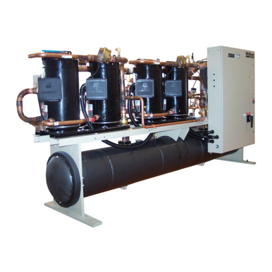
TGZ Scroll Compressor Templifiers™ ™ ™ ™
TGZ 040A to TGZ 190A, Packaged Water Heater
600 to 3100 MBH
R134a
Software: WGZDU0102E
Operation and Maintenance Manual
Group: Chiller
Part Number: 331975601
Effective: February 2011
Supercedes: June 2009
Corrections
2/22/11 Changed/added setpoints pgs 62, 63,+
OMM TGZ-1
Advertisement
Table of Contents

Subscribe to Our Youtube Channel
Related Manuals for McQuay TGZ 040A

Summary of Contents for McQuay TGZ 040A
- Page 1 Group: Chiller Part Number: 331975601 Effective: February 2011 Supercedes: June 2009 TGZ Scroll Compressor Templifiers™ ™ ™ ™ TGZ 040A to TGZ 190A, Packaged Water Heater Corrections 2/22/11 Changed/added setpoints pgs 62, 63,+ 600 to 3100 MBH R134a Software: WGZDU0102E...
-
Page 2: Table Of Contents
Manufactured in an ISO Certified facility ©2007 McQuay International. Illustrations and data cover the McQuay International product at the time of publication and we reserve the right to make changes in design and construction at anytime without notice. ™® The following are trademarks or registered trademarks of their respective companies: BACnet from ASHRAE;... -
Page 3: Introduction
Introduction General Description McQuay Type TGZ water heaters are scroll compressor refrigeration units that recover heat from warm fluid streams in the evaporator and deliver hot water, at a useful temperature, from the condenser to a heating load. They are designed for indoor installations only and are completely assembled, wired, charged and tested. -
Page 4: Tgz Scroll
13.4 15.5 23.3 46.3 40.9 38.8 122.3 Note: Nominal Flow Rate is gpm for 10ºF Delta-T at unit operating conditions of evaporator at 75/65ºF water temp and condenser at 110/30º F water temp. TGZ 040A through TGZ 190A OMM TGZ-1... - Page 5 TGZ150 C1612-164 4.85 5.68 14.50 18.1 11.4 54.1 31.3 15.1 93.4 TGZ170 C1612-184 4.89 6.50 14.60 18.4 13.1 55.0 31.8 17.4 95.0 TGZ190 C1612-184 6.24 7.38 18.66 23.3 14.8 69.6 40.2 19.7 120.3 OMM TGZ-1 TGZ 040A through TGZ 190A...
- Page 6 12.3 19.7 18.5 15.1 31.5 45.3 TGZ150 C1612-164 14.2 22.7 24.2 19.8 36.3 59.1 C1612-184 16.3 10.4 26.1 25.4 20.8 41.8 62.1 TGZ170 C1612-184 18.5 13.2 10.8 29.5 32.3 26.4 47.2 78.8 TGZ190 TGZ 040A through TGZ 190A OMM TGZ-1...
-
Page 7: Tgz Electrical Data
Single point power supply requires a single fused disconnect to supply electrical power to the unit. Compressor RLA values are for wire sizing purposes only and do not reflect normal operating current draw. OMM TGZ-1 TGZ 040A through TGZ 190A... - Page 8 Multiple point power supply requires a separate fused disconnect for each circuit to supply electrical power to the unit. External compressor overload option is only available for units with 140° F maximum leaving condenser water temperature. Wire sizes shown above are for standard ambient temperature and short runs of wire. TGZ 040A through TGZ 190A OMM TGZ-1...
- Page 9 3. External compressor overload option is only available for units with 140° F maximum leaving condenser water temperature. 4. Wire Sizes shown above are for standard ambient temperature and short runs of wire. OMM TGZ-1 TGZ 040A through TGZ 190A...
- Page 10 EXTERNAL OL'S SIZE CIRC.#1 CIRC.#2 CIRC.#1 CIRC.#2 TOTAL UNIT TOTAL UNIT NOTE: 1. "Maximum Fuse Sizes" are selected at approximately 225% of the largest compressor RLA plus 100% of other compressor RLA values. TGZ 040A through TGZ 190A OMM TGZ-1...
- Page 11 NOTES:. 1. "Size" is the maximum amperage rating for the terminals or the main electrical device... 2. "Connection" is the range of wire sizes that the terminals on the electrical device will accept. OMM TGZ-1 TGZ 040A through TGZ 190A...
- Page 12 NOTES: 1. "Size" is the maximum amperage rating for the terminals or the main electrical device. 2. "Connection" is the range of wire sizes that the terminals on the electrical device will accept. TGZ 040A through TGZ 190A OMM TGZ-1...
- Page 13 (2) 3/0 - 500 kcmil #14 - 2/0 #14 - 2/0 #6 - 350 kcmil #6 - 350 kcmil #14 - 2/0 #14 - 2/0 #6 - 350 kcmil #6 - 350 kcmil OMM TGZ-1 TGZ 040A through TGZ 190A...
- Page 14 (2) 3/0 - 500 kcmil #14 - 2/0 #14 - 2/0 #6 - 350 kcmil #6 - 350 kcmil #14 - 2/0 #14 - 2/0 #6 - 350 kcmil #6 - 350 kcmil TGZ 040A through TGZ 190A OMM TGZ-1...
- Page 15 Refer to the unit dimension drawings for the location of power and control connections. CAUTION To avoid equipment damage, use only copper conductors in main terminal block. Control Power A factory mounted control transformer is provided to supply the correct control circuit voltage. OMM TGZ-1 TGZ 040A through TGZ 190A...
-
Page 16: Field Wiring Diagram
4-20MA FOR DEMAND LIMIT (BY OTHERS) 0-10 VDC FIELD WIRING FOR TGZ COOLING TOWER BYPASS WITH MICROTECH CONTROLLER (BY OTHERS) DWG. 330538901 REV.0D (MOD) 0-10 VDC KDL 09-04-08 COOLING TOWER BYPASS (BY OTHERS) TGZ 040A through TGZ 190A OMM TGZ-1... - Page 17 Control Transformer Fuses, Primary Switches On Side Control 7/8-in. KO for Transformer control wiring Fuse, Secondary Optional Disconnect Switch (4) Compressor KO for Power Contactors Wiring Location for Grounding Lug Optional External Overloads OMM TGZ-1 TGZ 040A through TGZ 190A...
-
Page 18: Start-Up And Shutdown
Warranty Form” (Form No. 206036A) be completed to obtain full warranty benefits. Be sure to list the pressure drop across both vessels. This form is shipped with the unit and after completion should be returned to the McQuay Service Department through your sales representative. TGZ 040A through TGZ 190A... -
Page 19: Weekend Or Temporary Shutdown
14. Place pumpdown switch(es) PS1 and PS2 to the “auto pumpdown” position for restart and normal operation. 15. After running the unit for a short time, check the oil level in each compressor crankcase and for flashing in the refrigerant sightglass (see Maintenance section). OMM TGZ-1 TGZ 040A through TGZ 190A... -
Page 20: Sequence Of Operation
For a cold start-up (no compressors running), the first compressor will start at any temperature below 133.5°F. Each subsequent compressor will start after the Stage Up Timer has timed out and if the temperature is below the Control Band, 138.5°F in this case. TGZ 040A through TGZ 190A OMM TGZ-1... - Page 21 • If all of the compressors on a circuit are disabled, then the circuit will be disabled. • If both circuits have all of their compressors disabled, the Unit State will remain Off OMM TGZ-1 TGZ 040A through TGZ 190A...
- Page 22 They may also be controlled by the BAS or manually . Programming directions and the sequence of operation can be found beginning on page 42. TGZ 040A through TGZ 190A OMM TGZ-1...
-
Page 23: Microtech Ii Controller
Unit Enable Selection Enables unit operation from local keypad or digital input. Unit Mode Selection Selects standard cooling, ice, glycol, or test operation mode. OMM TGZ-1 TGZ 040A through TGZ 190A... - Page 24 3. Change field values in edit mode according to the following table: LEFT Default RIGHT Cancel Increment DOWN Decrement These four edit functions are indicated by one-character abbreviation on the right side of the display (this mode is entered by pressing the ENTER key). TGZ 040A through TGZ 190A OMM TGZ-1...
-
Page 25: Inputs And Outputs
0 VAC (No Flow) 24 VAC (Flow) Open Open Pump Down Switch #2 0 VAC (Stop) 24 VAC (Start) Open Condenser Water Flow Switch 0 VAC (No Flow) 24 VAC (Flow) Continued on next page. OMM TGZ-1 TGZ 040A through TGZ 190A... - Page 26 Fan Contactor Fan OFF Fan ON Condenser Fan #5&7 (R134a) Fan Contactor Fan OFF Fan ON Condenser Fan #8 Fan Contactor Fan OFF Fan ON Condenser Fan #6&8 Fan Contactor Fan OFF Fan ON TGZ 040A through TGZ 190A OMM TGZ-1...
-
Page 27: Expansion I/O Controller
0.5 °F 0 to 3.0 °F Max Pulldown Rate 1.0 °F 0.5 to 5.0 °F Max Rate (R134a) 1.0 ºF 0.5 to 5.0 ºF Evap Recirculate Timer 15 to 300 seconds Continued next page. OMM TGZ-1 TGZ 040A through TGZ 190A... - Page 28 5 to 15 seconds Recirc Timeout 3 minutes 1 to 10 minutes * Phase Voltage Protection * Ground Fault Protection Cooling Tower TGZ in Cooling Mode Tower Control None None, Temperature Tower Stages 0 to 2 TGZ 040A through TGZ 190A OMM TGZ-1...
- Page 29 Ice w/Glycol Low Evaporator Pressure Inhibit Loading and Unloading Mode Refrigerant Type Range Unit Mode = Cool R134a 26 to 54 psi Unit Mode = Cool w/Glycol, Ice R134a 12 to 54 psi w/Glycol OMM TGZ-1 TGZ 040A through TGZ 190A...
-
Page 30: Events & Alarms
AND Evaporator Flow Digital Input = No Flow. Action Taken: Rapid stop all circuits. Reset: This alarm can be cleared at any time manually, via the keypad, or via the BAS clear alarm signal. If active via trigger condition 1: TGZ 040A through TGZ 190A OMM TGZ-1... - Page 31 [60 – 1.6 x freeze error] with R22 and R407C refrigerant, limited to a range of 20- 60 seconds [60 – freeze error] with R410A refrigerant, limited to a range of 20-60 seconds OMM TGZ-1 TGZ 040A through TGZ 190A...
- Page 32 Trigger: Sensor shorted or open AND TGZ unit (refrig = R134a) AND operating in ‘heat’ mode. Action Taken: Normal stop all circuits Reset: This alarm can be cleared manually via the keypad if the sensor is back in range. TGZ 040A through TGZ 190A OMM TGZ-1...
- Page 33 After communication is established, when communication is lost to either EXB an immediate shutdown occurs. Action Taken: Rapid stop all circuits Reset: Auto clear when EXB1 is communicating with CP1. OMM TGZ-1 TGZ 040A through TGZ 190A...
-
Page 34: Limit Events
Reset: While still running, the event will be reset if evaporator pressure > (Low Evaporator Pressure - Hold set point + 8psi for R134a/R22/R407C or 13 psi for R410A). The event is also reset if the circuit state is no longer run. TGZ 040A through TGZ 190A OMM TGZ-1... - Page 35 Reset: Cond Sat Refr Temp > Condenser Freeze Set Point plus 2°F. Suction Temperature Sensor Fail Event description (as shown on screen): SuctT Sensor Fail N Trigger: Sensor shorted or open. Action Taken: None. Reset: N/A OMM TGZ-1 TGZ 040A through TGZ 190A...
- Page 36 Event Log. All other entries are moved down in the Event Log and the last entry is dropped if 25 earlier event occurrences have been logged. Each Event Log entry includes an event description and a time and date stamp for the event occurrence. TGZ 040A through TGZ 190A OMM TGZ-1...
-
Page 37: Controller Operation
The leaving water reset input uses a 4-20mA signal to reset the leaving water set point to a higher value. The adjustment varies linearly from 0 to 10 F, with a reset of 0 for a 4mA signal and a reset of 10 for a 20mA signal. OMM TGZ-1 TGZ 040A through TGZ 190A... - Page 38 +/- 0.5°F when compared to standard look up tables for R410a. Evaporator Approach The evaporator approach shall be calculated for each circuit. For R22 and R410a refrigerant the equation is: Evaporator Approach = LWT – Evaporator Saturated Temperature TGZ 040A through TGZ 190A OMM TGZ-1...
- Page 39 When the Control source is set to BAS, the most recent BAS mode request shall go into effect even if it changed while the Control source was set to KEYPAD or DIGITAL INPUTS. OMM TGZ-1 TGZ 040A through TGZ 190A...
- Page 40 If the OAT drops below the low ambient lockout set point, then all running circuits will do a normal stop. Once the lockout has been triggered, no compressors will start until the OAT rises to the lockout set point plus 5°F. TGZ 040A through TGZ 190A OMM TGZ-1...
- Page 41 Unit Alarm OR Unit Switch Off OR No Compressors Running AND [Unit Mode = Ice AND Ice Delay Active] OR No Compressors Running AND [No Circuit Available] Unit State Diagram Power On Pumpdown Auto OMM TGZ-1 TGZ 040A through TGZ 190A...
- Page 42 The Evaporator Water Flow Loss logic allows the Unit to shutdown compressors on a loss of flow up to two times every twenty-four hours before locking the unit out on a Evaporator Flow Loss Alarm. TGZ 040A through TGZ 190A OMM TGZ-1...
- Page 43 No Compressor Running LWT error < Start Delta] No Cond Refrig Freeze Event No Compressor Running [Cond Pump State = Start Start AND Flow Switch Closed] for time > Cond Pmp Recirc Time seconds OMM TGZ-1 TGZ 040A through TGZ 190A...
- Page 44 Condenser Water Flow Loss alarm and it will be locked out until this alarm is manually cleared. The twenty-four hour timer that limits the auto restart is reset when the control clock rolls over 00:00 each night. TGZ 040A through TGZ 190A OMM TGZ-1...
- Page 45 0. Otherwise, it shall be controlled as described below. Initial Valve Position When the condenser pump is not in the RUN state, the valve output will be set as a function of entering condenser water temperature (ECWT)) per the following graph. OMM TGZ-1 TGZ 040A through TGZ 190A...
- Page 46 Mode (above) except that (1) it will be kept at zero until the first fan stage is ON and (2) the following set points do not apply. Valve Control Range (Min) Valve Control Range (Max) Valve Type TGZ 040A through TGZ 190A OMM TGZ-1...
- Page 47 Stage Down Now = True If Unit Mode = Cool AND LWT error < (-0.5 * Control band - stop delta) AND One compressor running AND Stage down timer expired THEN Stage Down Now = True OMM TGZ-1 TGZ 040A through TGZ 190A...
- Page 48 Evaporator Pressure Hold set point. A Low Evaporator Pressure Unload event will be recorded in the Event Log. If the evaporator pressure drops below the Low Evaporator Pressure Unload setpoint and one compressor on the circuit is running then the following table applies. TGZ 040A through TGZ 190A OMM TGZ-1...
- Page 49 355 psi. As you can see, for each occurrence the discharge pressure must get lower and lower (based on Step-Increase value) before the circuit is allowed to again load. This logic is intended to prevent excessive cycling of compressors. OMM TGZ-1 TGZ 040A through TGZ 190A...
- Page 50 (with 6 compressors) Stage Stage 25.0 50.0 75.0 100.0 16.7 33.3 50.0 66.7 83.4 100.0 Network Limit (%) Network Limit (%) In order to allow all stages to run, a signal of 100.0% is required. TGZ 040A through TGZ 190A OMM TGZ-1...
- Page 51 The liquid line output shall be on any time a compressor on the circuit is running and the circuit is not performing a pump down. This output should be off at all other times. OMM TGZ-1 TGZ 040A through TGZ 190A...
-
Page 52: Exv Control
‘MaxOpPress’ set point (found on “SET COMP SPs (6) screen) and overloading the compressors. The electronic expansion valves (EEV) will close to prevent the operating circuit’s evaporator pressure from exceeding the ‘MaxOpPress’ set point. TGZ 040A through TGZ 190A OMM TGZ-1... -
Page 53: Using The Controller
After pressing the “EVAPORATOR” menu button, the selected data screen will show: VIEW EVAP (screen data) (screen data) (screen data) The arrow keys will automatically return to the “scroll” mode at this time. OMM TGZ-1 TGZ 040A through TGZ 190A... - Page 54 1. Change another setpoint in this menu by scrolling to it with the ENTER key. 2. Using the ENTER key, scroll to the first line in the menu. From there the ARROW keys can be used to scroll to different menus. TGZ 040A through TGZ 190A OMM TGZ-1...
-
Page 55: Menu Screens
Figure 8 going from left to right and down when there are sub-menus. Many menus are self-explanatory. A Setpoint menu allows selection of whether the unit has a water-cooled condenser, WaterCooled = Y (Yes). OMM TGZ-1 TGZ 040A through TGZ 190A... - Page 56 When more than one screen are stacked (i.e., relate to each other on the same subject), they are numbered sequentially with the numbers appearing in the upper-right corner. VIEW UNIT STATUS (2) Demand Limit=Stg 4 Network Limit=Stg 4 TGZ 040A through TGZ 190A OMM TGZ-1...
- Page 57 LWT Target = XX.X° ° ° ° F LWT Target = XX.X° ° ° ° F VIEW UNIT TEMP LWT Rate= XX.X ° ° ° ° F Control Band= XX.X° ° ° ° F OMM TGZ-1 TGZ 040A through TGZ 190A...
- Page 58 Starts = XXXXX If # of Compresors = 6 VIEW CIRCUIT 1 Comp5=Off Hours = XXXXX Starts = XXXXX VIEW CIRCUIT 2 VIEW CIRCUIT#2 Comp 2 = OFF Hours = XXXXX Starts = XXXXX TGZ 040A through TGZ 190A OMM TGZ-1...
- Page 59 VIEW REFRG Cir 1 (5) EXV Ctrl = XXX EXV Pos = XXX.X% SH Target = XX.X° ° ° ° F TGZ Units Only (R134a) VIEW REFRG Cir 1 (6) EXV Ctrl Range XX.X% ---XX.X% OMM TGZ-1 TGZ 040A through TGZ 190A...
- Page 60 Stages setpoint (0 if Tower Control = None). This screen shows the number of tower fans “on” for each circuit. This screen will show the fans “on” whether they are actually connected to and controlled by the MicroTech II controller or not. TGZ 040A through TGZ 190A OMM TGZ-1...
- Page 61 Set Unit Setpoints SET UNIT SPs (1) Unit Enable = OFF Unit Mode = COOL Source = KEYPAD Unit Enable settings can be OFF and ON as determined from the Unit Enable setpoint. OMM TGZ-1 TGZ 040A through TGZ 190A...
- Page 62 Heating Mode SET UNIT SPs SET UNIT SPs Cond Delta T – XX.X° ° ° ° F Cond Recirc=XXX sec Cond Recirc=XXX sec Cond Pump = #1 Only Cond Pump = #1 Only TGZ 040A through TGZ 190A OMM TGZ-1...
- Page 63 (psi) SET UNIT SPs (13) LWT Sensors Evap offset= 00.0° ° ° ° F Cond Offset= 00.0 SET UNIT SPs (14) EWT Sensors Evap offset= 00.0° ° ° ° F Cond Offset= 00.0 OMM TGZ-1 TGZ 040A through TGZ 190A...
- Page 64 Start-Start is the time required before starting a compressor after the last time it has started. Do not change default values of 5/10 minutes. SET COMP SPs InterStgUp =XXXsec InterStgDown= XXsec Clear Cycle Tmr = NO TGZ 040A through TGZ 190A OMM TGZ-1...
- Page 65 LowEvPrUnld is in effect and the lag compressor will be shut off to unload the unit. If one compressor is running, the LowEvPrHold is in effect and the lag compressor is prevented from starting, thereby holding the unit capacity. OMM TGZ-1 TGZ 040A through TGZ 190A...
- Page 66 LowAmbientLock applies to units with air-cooled condensers and prevents unit operation below the setting. The available range is -2 F to 60 F with a default of 35 F. WaterCooled=ON SET ALARM LIMITS (5) Cond Freeze= XX.X °F CondFlowProof= XX sec TGZ 040A through TGZ 190A OMM TGZ-1...
- Page 67 SET TOWER SPs (1) Tower Control= None Tower Stages = X StageUP/DN=XXX/XXX% When Tower Control is None the control of condenser water temperature is not by the MicroTech II controller and assumed to be furnished elsewhere. OMM TGZ-1 TGZ 040A through TGZ 190A...
- Page 68 New %Position = Old %Position + Increment/10 Valve Stage, controls from the fan stage setpoint in use. It is recommended that the Valve Setpoint method explained above be used rather than this mode. TGZ 040A through TGZ 190A OMM TGZ-1...
- Page 69 0 to 10 VDC (Valve Type = NC) 10 to 0 VDC (Valve Type = NO) SET TOWER SPs (5) Valve SP = XXX ° ° ° ° F Valve DB = XX.X ° ° ° ° F OMM TGZ-1 TGZ 040A through TGZ 190A...
- Page 70 2= OFF 4= OFF 2= OFF 4= OFF 6= OFF Wa t er Co o led = O N TEST UNIT Cond Pump 1 = OFF Cond Pump 2 = OFF TwrFan1=OFF Fan2=OFF TGZ 040A through TGZ 190A OMM TGZ-1...
- Page 71 ENTER again. Once the correct password has been entered, the previously selected screen will reappear. Once a password has been entered, it will remain valid for 15 minutes after the last key-press. OMM TGZ-1 TGZ 040A through TGZ 190A...
-
Page 72: Bas Interface
Active alarms 2 Active alarms 3 Active alarms 4 Active alarms 5 Active alarms 6 Active alarms 7 Active alarms 8 Active alarms 9 Active alarms 10 Active alarms 11 Continued next page. TGZ 040A through TGZ 190A OMM TGZ-1... - Page 73 Network chiller enable set point Chiller enable status Active alarm indicator Chiller run enabled Chiller local control Chiller capacity limited Evap flow Cond flow Network chiller enable default set point Ignore network defaults Network clear alarm signal OMM TGZ-1 TGZ 040A through TGZ 190A...
-
Page 74: Optional Controls
If only one hot gas valve is specified for the unit, the hot gas bypass is wired in the first refrigerant circuit and TGZ 040A through TGZ 190A OMM TGZ-1... - Page 75 The hot gas line can become hot enough to cause injury in a very short time; care should be taken during valve checkout. Figure 11, Hot Gas Bypass Piping Figure 12, Hot Gas Bypass Adjustment Range OMM TGZ-1 TGZ 040A through TGZ 190A...
-
Page 76: System Maintenance
Failure to do so can result in serious personal injury. If motor or compressor damage is suspected, do not restart until qualified service personnel have checked the unit. TGZ 040A through TGZ 190A OMM TGZ-1... -
Page 77: Electrical Terminals
Before resealing the compressor, purge the crankcase by opening the suction valve slightly for 1 or 2 seconds. Close the oil port, open the compressor valves and restore the system to operation. OMM TGZ-1 TGZ 040A through TGZ 190A... -
Page 78: Oil Equalization
If the crankcase is cool (below 80°F) (26.7°C) and the oil level in the sight glass is full to top, allow more time for oil to warm before starting the compressor. The crankcase heaters are on whenever power is supplied to the unit and the compressor is not running. TGZ 040A through TGZ 190A OMM TGZ-1... -
Page 79: System Service
Be sure to replace the coil on its mounting stud before returning pumpdown switch(es) PS1 and PS2 to the “auto pumpdown” position. To replace the entire solenoid valve, follow the steps involved when changing a filter- drier. OMM TGZ-1 TGZ 040A through TGZ 190A... -
Page 80: Troubleshooting Chart
Reset thermostat setting to fit Stages not set for application. application. Compressor Erratic water thermostat. Replace Loading/Unloadin Insufficient water flow. Adjust flow. g Intervals Too Short Table continued on next page. TGZ 040A through TGZ 190A OMM TGZ-1... - Page 81 Blown valve plate gasket. Replace gasket. Freeze Thermostat set too low. Reset to 42° F (6° C) or above. Protection Low water flow. Adjust flow. Opens Low suction pressure. See “Low Suction Pressure.” OMM TGZ-1 TGZ 040A through TGZ 190A...
- Page 82 TGZ 040A through TGZ 190A OMM TGZ-1...
- Page 84 Warranty and Terms of Sale All McQuay equipment is sold pursuant to McQuay’s Standard Terms and Conditions of Sale and Limited Product Warranty. Consult your local McQuay Representative for warranty details. Refer to form 933- 430285Y-00-A (09/08).
Need help?
Do you have a question about the TGZ 040A and is the answer not in the manual?
Questions and answers