Table of Contents

Summary of Contents for Magnetic Instrumentation 2130
- Page 1 Fluxmeter Model 2130 Instruction Manual Revision 3, 18-March-2013 Starting with Serial Number 41554 8431 Castlewood Drive, Indianapolis, IN 46250 USA (317) 842-7500 • Fax (317) 849-7600 E-Mail: maginst@maginst.com • www.maginst.com...
- Page 3 The CAUTION Message indicates that a condition exists that may cause damage to the Model 2130. 000.01 kMT The display symbol indicates the information displayed by the 100 kMT NORM Model 2130 after a preceding step is executed. The EXAMPLE message indicates that an example follows. EXAMPLE:...
-
Page 4: Table Of Contents
1.5.2 I/O Specifications ........................ 1-5 1.5.3 General Specifications ......................1-6 1.5.4 Radiated RF Immunity ......................1-6 INITIAL SETUP ..........................2-1 ..........................2-1 NPACKING 2130 F ....................2-1 ODEL UNCTIONAL HECK USING THE MENU SYSTEM ......................3-1 ..................... 3-1 ENERAL ESCRIPTION ...................... - Page 5 CONTENTS 4.5.1 Maxwell-Turns ........................4-3 4.5.2 Maxwells ..........................4-4 4.5.3 Gauss ........................... 4-4 4.5.4 Tesla ............................ 4-4 4.5.5 Bdi-Gauss ..........................4-4 4.5.6 Bdi-Tesla ..........................4-4 ......................4-4 ELECTING A EARCH 4.6.1 Number of Turns ........................4-4 4.6.2 Coil Resistance ........................4-4 4.6.3 Coil Area ..........................
- Page 6 CONTENTS List of Figures 1.2.1 M 2130 F ....................1-2 IGURE ODEL RONT ANEL 1.3.1 M 2130 R ....................1-3 IGURE ODEL ANEL 1.4.1 M 2130 D ......................1-4 IGURE ODEL ISPLAY 3.3.1 M 2130 M ....................3-2 IGURE ODEL YSTEM 4.2.1 S...
-
Page 7: Introduction
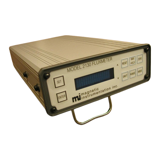
1. INTRODUCTION 1.1 Overall Description 1.1.1 Overview The Magnetic Instrumentation, Inc. Model 2130 Fluxmeter is a compact, precision, microprocessor-controlled instrument capable of measuring static, alternating, or pulsed magnetic fields. Twelve measurement ranges allow the user to configure the meter for maximum resolution and accuracy from 100 kMaxwells to 100 MMaxwells (1 mWeber - 1 Weber) full scale. -
Page 8: Front Panel Description
(increments) through menu options and parameters. MAX HOLD Key Switches between NORMAL and MAX HOLD modes of operation. ZERO Key Allows the user to zero and calibrate the Model 2130’s integrator. MODE Key Switches between the NORMAL, DUAL LIMITS, and RELATIVE modes of operation. -
Page 9: Rear Panel Description
Connects the power cord to the Model 2130. RECEPTACLE FUSE HOLDER Contains the line fuse for the 2130 meter. This fuse does not affect the operation of the meter from a ±9 VDC power source. PROBE Connects a sense coil or Helmholtz coil to the Model 2130. -
Page 10: Display Description
Indicates the measurement units currently selected. DC/AC Indicates whether the Model 2130 is measuring a static or alternating flux. This space is blank when the meter is in DC mode. The letters AC are displayed when the meter is in AC mode. -
Page 11: Specifications
0.800 1 ms Pulse width Analog Output - 10 0.150 0.400 Specification is for the deviation of the analog output compared to the Model 2130 display value. Table 1.5.1 Accuracy Specifications 1.5.2 I/O Specifications Interface Specification Serial RS-232C 9600 baud rate, 8 data bits, no parity, 1 stop bit, no handshaking... -
Page 12: General Specifications
CHAPTER 1 INTRODUCTION 1.5.3 General Specifications Property Specification Size 12.6" x 6.9" x 2.9" ( L x W x H ) Weight 7.5 lbs. Power 115 or 220 VAC 50/60 Hz Fuse 0.25A 250V type 3AG Table 1.5.3 General Specifications 1.5.4 Radiated RF Immunity When operated in a field of 3.0V/M at frequencies from 26 MHZ to 500 MHZ reading may change by as much as 40 KMT. - Page 13 Avoid dropping or jarring the Model 2130. Store the Model 2130 in a cool dry environment when it is not in use. Do not use solvents or abrasives to clean the exterior of this instrument.
-
Page 14: Initial Setup
If possible, keep the original shipping container. In the event that the Model 2130 needs to be returned to Magnetic Instrumentation, Inc., the original shipping container will provide the best means of repackaging the fluxmeter and accessories. -
Page 15: Table 2.2.1 Default Configuration
Press the front panel SET key to disable the menu system 00.000 MMT and return to normal operation. 10 MMT NORM k) The Model 2130 is now set to factory default configuration. The following table indicates the default configuration settings which are now enabled. Menu Number Parameter Default Value... -
Page 16: Using The Menu System
3.1 General Menu Description The Model 2130 menu system is composed of a three-level hierarchical arrangement of optional settings and configuration information. The top level of the menu system allows access to the major groups of menu options and configuration. Some of these major groups are divided into sub-menus. -
Page 17: Figure 3.3.1 Model 2130 Menus
No, This set, All sets 9. Default +45° 0 to 10. GPIB Address DC or 11. DC/AC Pads All Active 12. Keypad Active Yes or No Setup # 1 to Setup # 8 13. Setup # Figure 3.3.1 Model 2130 Menu System... -
Page 18: Table 3.3.1 Menu Items
“All sets” parameter will set all eight setups to default. Note that resetting the Model 2130 to factory default will set the GPIB address to 1. If the GPIB remote interface is used to set the Model 2130 to factory default, communication may be lost if the fluxmeter GPIB address was previously set to any address other than 1. -
Page 19: Setting The Display Period
CHAPTER 3 USING THE MENU SYSTEM 3.4 Setting the Display Period a) Press the front panel SET key until the menu system is active and is at the top menu level. This is indicated by the 1. Display Period appearance of the “SET” message on the top row of the display. -
Page 20: Setting The Measurement Units
CHAPTER 3 USING THE MENU SYSTEM 3.5 Setting the Measurement Units a) Press the front panel SET key until the menu system is active and is at the top menu level. This is indicated by the 1. Display Period appearance of the “SET” message on the top row of the display b) Press the front panel UP (RESET) key or the DOWN (DRIFT) key until the menu system is set to the Change Unit menu... -
Page 21: Setting The Coil Resistance
CHAPTER 3 USING THE MENU SYSTEM 3.6 Setting the Coil Resistance a) Press the front panel SET key until the menu system is active and is at the top menu level. This is indicated by the xx. xxxxxxxxxxxxxx appearance of the “SET” message on the top row of the display b) Press the front panel UP (RESET) key or the DOWN (DRIFT) key until the menu system is set to the Coil Parameter menu... -
Page 22: Setting The Coil Area
CHAPTER 3 USING THE MENU SYSTEM 3.7 Setting the Coil Area a) Press the front panel SET key until the menu system is active and is at the top menu level. This is indicated by the 1. Display Period appearance of the “SET” message on the top row of the display. -
Page 23: Setting The Coil Turns
CHAPTER 3 USING THE MENU SYSTEM 3.8 Setting the Coil Turns a) Press the front panel SET key until the menu system is active and is at the top menu level. This is indicated by the 1. Display Period appearance of the “SET” message on the top row of the display. -
Page 24: Setting The Helmholtz Constant For Use With Helmholtz Coils
CHAPTER 3 USING THE MENU SYSTEM 3.9 Setting the Helmholtz Constant for use with Helmholtz Coils a) Press the front panel SET key until the menu system is active and is at the top menu level. This is indicated by the 1. -
Page 25: Setting The Magnet Volume
CHAPTER 3 USING THE MENU SYSTEM 3.10 Setting the Magnet Volume a) Press the front panel SET key until the menu system is active and is at the top menu level. This is indicated by the 1. Display Period appearance of the “SET” message on the top row of the display. -
Page 26: Viewing The Calibration Coefficient
CHAPTER 3 USING THE MENU SYSTEM 3.11 Viewing the Calibration Coefficient a) Press the front panel SET key until the menu system is active and is at the top menu level. This is indicated by the 1. Display Period appearance of the “SET” message on the top row of the display. -
Page 27: Setting The Lower Limit
CHAPTER 3 USING THE MENU SYSTEM 3.12 Setting the Lower Limit a) Press the front panel SET key until the menu system is active and is at the top menu level. This is indicated by the 1. Display Period appearance of the “SET” message on the top row of the display. -
Page 28: Setting The Upper Limit
CHAPTER 3 USING THE MENU SYSTEM 3.13 Setting the Upper Limit a) Press the front panel SET key until the menu system is active and is at the top menu level. This is indicated by the 1. Display Period appearance of the “SET” message on the top row of the display. -
Page 29: Setting The Relative Offset
CHAPTER 3 USING THE MENU SYSTEM 3.14 Setting the Relative Offset a) Press the front panel SET key until the menu system is active and is at the top menu level. This is indicated by the 1. Display Period appearance of the “SET” message on the top row of the display. -
Page 30: Enabling/Disabling The Drift Rates
CHAPTER 3 USING THE MENU SYSTEM 3.15 Enabling/Disabling the Drift Rates a) Press the front panel SET key until the menu system is active and is at the top menu level. This is indicated by the 1. Display Period appearance of the “SET” message on the top row of the display. -
Page 31: Setting Factory Default Configuration
CHAPTER 3 USING THE MENU SYSTEM 3.16 Setting Factory Default Configuration a) Press the front panel SET key until the menu system is active and is at the top menu level. This is indicated by the 1. Display Period appearance of the “SET” message on the top row of the display. -
Page 32: Setting The Gpib Address
CHAPTER 3 USING THE MENU SYSTEM 3.17 Setting the GPIB Address a) Press the front panel SET key until the menu system is active and is at the top menu level. This is indicated by the 1. Display Period appearance of the “SET” message on the top row of the display. -
Page 33: Setting The Dc/Ac Function
CHAPTER 3 USING THE MENU SYSTEM 3.18 Setting the DC/AC Function a) Press the front panel SET key until the menu system is active and is at the top menu level. This is indicated by the 1. Display Period appearance of the “SET” message on the top row of the display. -
Page 34: Setting The Keypad Active Function
CHAPTER 3 USING THE MENU SYSTEM 3.19 Setting the Keypad Active Function g) Press the front panel SET key until the menu system is active and is at the top menu level. This is indicated by the 1. Display Period appearance of the “SET”... -
Page 35: Selecting The Active Setup
CHAPTER 3 USING THE MENU SYSTEM 3.20 Selecting the active Setup # a) Press the front panel SET key until the menu system is active and is at the top menu level. This is indicated by the 1. Display Period appearance of the “SET”... -
Page 36: Measurement Considerations
To realize the full potential of the Model 2130, the user must become familiar with some general guidelines for making measurements. This section will cover some of the basic configurations of the Model 2130 as well as the use of the auxiliary outputs (analog and dual limits). -
Page 37: Ac Mode
(an alternating field, by definition, changes polarity). Note that the Model 2130 does not indicate RMS values in the true sense. In the AC mode, the output of the integrator is actually AC coupled to the RMS detector. This helps eliminate the problem of integrator drift causing the apparent measured AC field from drifting as well. -
Page 38: Dual Limits Mode
(refer to Sections 3.12 - 3.13 on setting the upper and lower limit). The Model 2130 display will indicate if the measurement is between the upper and lower limits, less than the lower limit, or above the upper limit. -
Page 39: Maxwells
. To use this measurement unit, both the number of turns, and the coil area must be entered into the Model 2130’s coil parameter menu. The shape and area of the sample must be very close to those of the search coil. -
Page 40: Coil Area
Therefore using a search coil with a larger cross sectional area allows the Model 2130 to be set to a higher range. The size of the search coil will often be a compromise between the signal strength and the spatial resolution that is required. -
Page 41: Using The Zero Key
NO to prevent the meter from tracking desired signal as though it were drift error. Each press of the DRIFT button on the front panel of the 2130 cycles the meter to the next of the four possible drift adjustment modes. There is no "manual" drift adjustment. -
Page 42: Using The Analog Output
Model 2130 will set the Limits High Output to a logic low state. When the Model 2130 is not in the Dual Limit mode all the limit outputs are high. Refer to Section 3.12, “Setting the Lower Limit” and Section 3.13, “Setting the Upper Limit”, to define the upper and lower limit parameters. -
Page 43: Using The Remote Reset
RESET key without the use of the RS-232 or IEEE-488 interfaces. If a logic low (< 0.8 V) is placed on the Remote Reset pin, the Model 2130 will respond as if the front panel RESET key were pressed. Refer to Section 8.3 “Auxiliary Connector Pin Assignments” for Remote Reset pin designation. -
Page 44: Coil Parameters
See also Section 4.6.3. 4.13.3 Sample Volume When a Helmholtz coil is used with the Model 2130, the volume of the magnet sample must be known and must be entered using the Model 2130’s menu system. Any error in the magnet volume will directly affect the accuracy of the measurement. -
Page 45: Theory Of Operation
CHAPTER 5 THEORY OF OPERATION 5. THEORY OF OPERATION 5.1 Measurement of Flux The instantaneous voltage e induced in a coil having N turns that is cut by ∅ lines of transverse flux during time t is given by: ∅ = −... -
Page 46: Measurement Of Flux Density
In the preceding explanations, a method of integration was required to measure both total flux and flux density. Most electronic fluxmeters (the Model 2130 included) accomplish this function with a Miller integrator. The following figure is a simplified representation of the Model 2130’s integrator. - Page 47 CHAPTER 5 THEORY OF OPERATION where v is in volts I is in amps t is in seconds and c is in farads. Substituting equation 7 for I and C for c gives: Since the junction of C and R is at virtual ground, the voltage developed across C is equal to the integrator output voltage e...
-
Page 48: Remote Operation
When using the RS-232 interface, each character received by the Model 2130 is echoed to the host PC. Once a character is sent to the Model 2130, no further characters should be sent until the echoed character is received. When the IEEE488 interface is used, characters are... - Page 49 The parameter must always contain two ASCII numeric characters. While the Model 2130 menu system is enabled, the user may scroll through the menu options and parameters by simulating front panel key presses, or by sending numeric characters corresponding to the menu option or parameter.
-
Page 50: Command Reference
Parameter: drift rate number Returns: none Description: Sets the Model 2130 to the Drift Rate specified by drift rate number . The drift rate number is defined in the following table. Example: Sending the command “q01” will set the Model 2130 to Lo Drift Rate adjustment. - Page 51 Parameter: none Returns: gain Description: Returns the current gain setting of the Model 2130. Value can be 1, 2, 4, or 8. Example: Sending the GAIN QUERY command while the Model 2130 gain is set to 8 will return the following string.
-
Page 52: Table 6.4.2 Mode Numbers
Parameter: max hold number Returns: none Description: Sets the Model 2130 to the Max Hold mode specified by max hold number . The max hold number is defined in the following table. Example: Sending the command “h01” will set the Model 2130 in Max Hold mode. - Page 53 Parameter: mode number Returns: none Description: Sets the Model 2130 to the mode specified by mode number . Mode number is defined in the following table. Example: Sending the command “m01” will set the Model 2130 to Dual Limits mode.
- Page 54 Description: Returns a string of characters indicating the current range setting the Model 2130. Example: Sending the RANGE QUERY command while the Model 2130 is set to the 100 kMT range will return the following string: 100 kMT <CR><LF> RESET (Up arrow) Character: “R”...
-
Page 55: Service
Configuration” for instructions on resetting the meter configuration to factory default. Table 7.2.1 is a listing of messages that may be displayed by the Model 2130. Some of these messages will appear each time power is supplied to the Model 2130 while other messages will only appear in the event of an error. - Page 56 This message is displayed each time power is applied to the Model 2130. “Power Supply Error” Indicates a failure in the Model 2130 ±5V power supply. When the Model 2130 is being powered from an external ±9VDC source, this error will result if the external source voltage is too low.
-
Page 57: Connector Pin Assignments
CHAPTER 8 CONNECTOR PIN ASSIGNMENTS 8. CONNECTOR PIN ASSIGNMENTS 8.1 GPIB Connector Pin Assignments Figure 8.1.1 GPIB Connector NAME DESCRIPTION DIO 1 Data Input / Output 1 DIO 2 Data Input / Output 2 DIO 3 Data Input / Output 3 DIO 4 Data Input / Output 4 End or Identify... -
Page 58: Rs-232 Connector Pin Assignments
CHAPTER 8 CONNECTOR PIN ASSIGNMENTS 8.2 RS-232 Connector Pin Assignments Figure 8.2.1 RS-232 Connector NAME DESCRIPTION pins 1, 4, and 6 internally shorted Transmit Data Receive Data pins 1, 4, and 6 internally shorted Ground pins 1, 4, and 6 internally shorted pins 7 and 8 internally shorted pins 7 and 8 internally shorted Not Connected... -
Page 59: Auxiliary Connector Pin Assignments
CHAPTER 8 CONNECTOR PIN ASSIGNMENTS 8.3 Auxiliary Connector Pin Assignments Figure 8.3.1 Auxiliary Connector NAME DESCRIPTION Common Limits High Output (active low) Limits Low Output (active low) Common Limits Pass Output (active low) Remote Not Reset (active low) Not Connected Probe Memory +5V +Batt +9V Battery Connection... -
Page 60: Units Conversion
CHAPTER 9 UNITS CONVERSION 9. UNITS CONVERSION 9.1 CGS - SI Conversion SI Units multiplied by Conversion equals CGS Units. Quantity SI Units Conversion CGS Units SI/CGS Electric Current [I] Ampere [A] abampere Flux Density [B] Tesla [T] Gauss [G] Force Newton [N] dyne [dyn]... -
Page 61: Declaration Of Conformity
DECLARATION OF CONFORMITY 10. DECLARATION OF CONFORMITY We, Magnetic Instrumentation, .declare under sole responsibility that the Model 2130 Fluxmeter to which this declaration relates is in conformity with emissions requirements CENELEC document EN5022 and for class B ITE and immunity requirements of CENELEC document EN50082-1, Part 1: Residential, Commercial, Light Industry (sections covered: Environmental Phenomena, RF Electromagnetic Field, Electrodischarge Air, Fast Transient, and Electrostatic Discharge Contact.) -
Page 62: Index
INDEX 11. INDEX Power ............1-3 Probe ............1-3 AC Function ........... 4-2 RS-232 ..........1-3, 8-2 Analog Output ..........4-7 DC Function ........... 4-1 Bdi-Gauss ............4-4 Default Configuration ........2-2 Bdi-Tesla ............4-4 Display ............1-2 DC/AC ............1-4 description .......... - Page 63 INDEX system diagram ........... 3-2 Sources of Error ..........4-8 Miller Integrator ..........5-2 Specifications MODE Key ............. 1-2 accuracy ............1-5 Dual Limit Outputs ........1-5 general ............1-6 Normal Mode ..........4-2 GPIB ............1-5 I/O ............... 1-5 input ............
Need help?
Do you have a question about the 2130 and is the answer not in the manual?
Questions and answers