
Summary of Contents for Minster SCRB-68
- Page 1 Manual No. 679A MINST R ® SCRB-68 EDDY CURRENT COUPLING CONTROLS DESCRIPTION OPERATION MAINTENANCE MINSTER SOLID STATE CONTROLS REPAIR PARTS 8952-574 $5.00...
- Page 2 Manual No. 679A MINST R ® SCRB-68 EDDY CURRENT COUPLING CONTROLS DESCRIPTION OPERATION MAINTENANCE MINSTER SOLID STATE CONTROLS REPAIR PARTS 8952-574 $5.00...
- Page 3 If technical assistance is desired, please contact the Minster Service Department. REGARDING WARRANTY TERMS OF THE WARRANTY ARE FULLY DOCUMENTED IN THE MINSTER WARRANTY. A COPY OF THAT WARRANTY IS INCLUDED IN THE COMPOSITE SERVICE MANUAL; ADDITIONAL COPIES ARE AVAILABLE UPON REQUEST.
-
Page 4: Table Of Contents
CONTENTS Page COMPONENT IDENTIFICATION ............DESCRIPTION . -
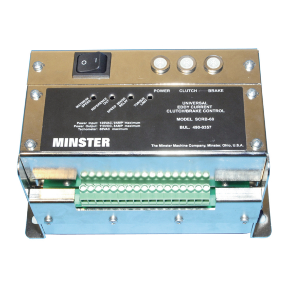
Page 5: Component Identification
COMPONENT IDENTIFICATION Power Switch Indicators Terminal Strip Figure 1. SCRB-68 with cover removed. Figure 2. SCRB-68 rear view. — 4 —... -
Page 6: Description
The control consists of a rugged metal hous- which varies in direct relation to the output speed of the ing. The SCRB-68 control may be used with drives drive is provided for use with programmable controls requiring up to 900 watts at 90 volts D.C. -
Page 7: Explanation Of Eddy Current Coupling
EXPLANATION OF A high strength iron drum is connected to the driveshaft of the constant speed motor and rotates at the speed of EDDY CURRENT COUPLING the motor. This drum is the driving member and, in prin- (See Figure 3) ciple, serves as a series of conductor loops as well as Before entering into a circuit description of the Eddy a magnetic flux carrier. -
Page 8: Eddy Current Brake
This voltage is fed into the SCRB-68 con- interacts with the stationary field to develop braking trol where it is converted from a frequency signal to a torque. -
Page 9: Function Of The Speed Sensitive Relay
POWER OFF/ON drive whenever the press is stopped. A power switch is mounted on the face of the SCRB-68 The speed sensitive relay is used as a checking device Eddy Current Coupling Control and provides a conve-... -
Page 10: Adjustments
1. Drive reaches full speed before operator's speed wire connected to terminal 9 (R signal) of the SCRB-68 control selector is set to maximum. This situation control and temporarily jumper terminals 9 (R signal) results in the control running wide open in an attempt and 8 (P1 signal). -
Page 11: To Adjust The Torque Limit Potentiometer
This poten- 4. Double check adjustment by varying press speed tiometer is located on the SCRB-68 unit and is labeled through the selected speed operating point and “Torque Limit” and is located last from the left when observing relay drop out point. -
Page 12: Reference Out
REFERENCE OUT (PLC ANALOG INPUTS): The reference out potentiometer is located on the front of the SCRB-68 unit. For PLC analog inputs, the output level is typically set at 95% of the maximum allowable input voltage. For example, with an analog input range configured for 0- 10 volts DC, the output voltage would be adjusted so that 9.5 volts DC is present when the output terminals... -
Page 13: Control Replacement
CONTROL REPLACEMENT WARNING The SCRB-68 is the latest in a series of eddy current adjustable speed drive controls produced by MIN- STER. This latest generation unit incorporates the VOLTAGE THAT COULD BE FATAL TO HUMAN LIFE functions of all of the previous controls. As such it can IS PRESENT WITHIN THE ELECTRICAL CONTROL replace any of those previous controls. - Page 14 Then refer to the Adjust- permit removal of the unit. Then remove the unit ment section of this manual. from the control panel. 4. Install the SCRB-68 unit in the control panel and WARNING tighten the four (4) associated mounting screws securely.
-
Page 15: Option B: Conversion From A Scrb 42/48 To A Scrb 68
1; the sec- ond fuse is to be installed in series with the terminal 2 4. Install the SCRB-68 unit in the control panel and of the SCRB-68 control. tighten the four (4) associated mounting screws securely. - Page 16 possible. Begin by drilling and tapping four (4) #10 10. Run a #16 ga. MTW grade wire (or equivalent) - 24 holes in the control panel to anchor the fuse from the top of the second fuse to terminal “Y2” of holders.
-
Page 17: Option C: Conversion From A Scr 22/28 To A Scrb 68
Volt AC control power circuit. Install the fuse in series rent transformer. See Figure 8 for details. with terminal 1 on the SCRB-68 control. The Model SCRB-68 control has a terminal strip simi- The terminal strip designation of the late Model SCR- lar to that shown in Figure 8. -
Page 18: Installation Note
Return unit to Minster for repair. 4. Install the SCRB-68 unit in the control panel and As mentioned previously, the unit contains potentiome- tighten the four (4) associated mounting screws ters which must be adjusted to suit operating conditions securely. -
Page 19: Troubleshooting Guide
TROUBLESHOOTING GUIDE TROUBLE CHECK 1. Make certain 100 volts A.C. exists between terminals 1 (D signal) and 2 (Y2 signal) with the power switch on. A voltage of approximately 16 volts D.C. between terminals 8 (P1 signal) and 7(G1 signal) shows presence of the reference voltage. A voltage or approximately 90 volts D.C. -
Page 20: Voltage Guide
FACTORY CHECKOUT AND REPAIR SPECIFICATIONS If it is determined that a problem exists within the Supply SCRB-68, it can be returned to the factory for checkout and repair. Before returning the unit, contact the Min- • Voltage: 100-125VAC ster Repair Parts Department for a Returned Goods •... - Page 21 ADDITIONAL COMMENTS: — 20 —...
- Page 23 MINST R ® The Minster Machine Company, Minster, Ohio 45865, U.S.A. Phone: (419) 628-2331 / Fax: (419) 628-3517 Distributors strategically located throughout the world. MMC0311...
- Page 24 MINST R ® The Minster Machine Company, Minster, Ohio 45865, U.S.A. Phone: (419) 628-2331 / Fax: (419) 628-3517 Distributors strategically located throughout the world. MMC0311...
Need help?
Do you have a question about the SCRB-68 and is the answer not in the manual?
Questions and answers