
Summary of Contents for Indexator XR Series
- Page 1 Servicemanual ROTATOR XR 500 XR 500 C XR 600 XR 600 C IMPORTANT! Read through the service manual carefully and make sure that you understand the content before starting the service. 1104850 www.indexator.com 2017-10-25...
- Page 2 GENERAL This service manual has been produced inhouse Indexator and can show the special tools and equipment that are used in the production. Alternative equipment can also be used. Vi are contstantly improving our products and reserve the right to make design changes without introducing them on products that have already been delivered.The same applies to maintenance and other service...
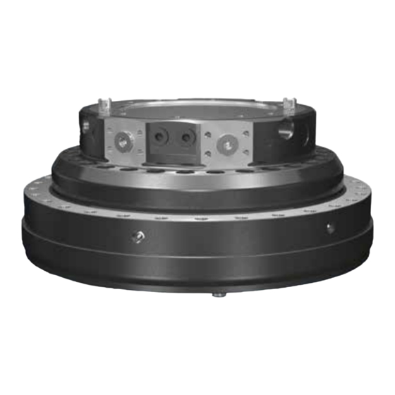
- Page 3 XR is a compact rotator with grapple- and rotation function. C models has an extra function for central greasing. That function is describes as a notification ”only C model” in the servicemanual. Components The components referred to in the servicemanual. This is a XR 600. 1104850 2017 10 25 © Indexator Rotator Systems AB...
- Page 4 333 Nm 1018 258 Smörjnippel Grease nipple M8x1 1070 861 Skruv Screw M8x65 33 Nm 6002 465 Tätningssats Seal kit XR500/XR600 5001 384 Propp Plug G1/2 5001 385 Propp Plug G3/4 1104850 2017 10 25 © Indexator Rotator Systems AB...
-
Page 5: Recommended Tools
To prolong the lifetime: Every 40 hours rotate 10 rounds. Recommended tools PART NO DESCRIPTION 1077 106 Glide seal remover 1 pcs 1104850 2017 10 25 © Indexator Rotator Systems AB... -
Page 6: Changing Seals
Contents This servicemanual describes: Changing seals..............................6-29 Changing bearing..............................30-36 Changing seals Put the rotator upside down and remove the manifold block. Remove the manifold block by loosen 5 pcs of M12 screws. 1104850 2017 10 25 © Indexator Rotator Systems AB... - Page 7 Lift up the transmission. Newer versions of transmission has two M10 holes. Use 2 pcs of M10 screws to create a good grip and prevent any risk of injury. NOTE! Risk of injury! 1104850 2017 10 25 © Indexator Rotator Systems AB...
- Page 8 Remove 5 pcs of M12x45 screws in block lower. LIft up block lower. Remove the outer tube. Remove the internal tube. 1104850 2017 10 25 © Indexator Rotator Systems AB...
- Page 9 Remove 2 pcs of M8x65 screws - holding the motor parts together. Remove stator plate lower. Assemble 2 pcs of M8 screws, with the total thread length 85 mm. That will lift the stator lower plate from the stator frame. 1104850 2017 10 25 © Indexator Rotator Systems AB...
- Page 10 The wiper seal is ordered separately, is not part of the seal kit. The wiper seal is only for XR500 and XR600 (not for c-models). Remove the seal in stator plate lower. 1104850 2017 10 25 © Indexator Rotator Systems AB...
- Page 11 Clean the seal seat thoroughly, using cotton buds and oil for example. Assemble a new seal. Assemble a new wiper seal (not for c-models). 1104850 2017 10 25 © Indexator Rotator Systems AB...
- Page 12 Remove 2 pcs of seals in stator plate lower, clean the seal seats and assemble new seals. Grease the seals on the inside surface. Remove the o-ring from the stator frame. 1104850 2017 10 25 © Indexator Rotator Systems AB...
- Page 13 Clean the seal seat. Lubricate the seal seat with oil. Assemble a new o-ring. 1104850 2017 10 25 © Indexator Rotator Systems AB...
- Page 14 85 mm. Make sure that they do not go through the part on the back side. Make sure that the holes in stator plate lower aligns with the two holes for M8x65 screws in the stator frame. 1104850 2017 10 25 © Indexator Rotator Systems AB...
- Page 15 Stator plate lower is in the end position when the wiper seal is visible. Assemble 2 pcs of M8x65 screws holding the motor parts together. Torque 33 Nm. 1104850 2017 10 25 © Indexator Rotator Systems AB...
- Page 16 That will make it easier to lift the motor off. Lift the motor off from stator upper. If needed knock carefully with a plastic mallet on the lower link to release the vacuum. Remove the o-ring in stator upper. 1104850 2017 10 25 © Indexator Rotator Systems AB...
- Page 17 Clean the seal seat. Assemble a new o-ring. Remove the seal in stator upper. 1104850 2017 10 25 © Indexator Rotator Systems AB...
- Page 18 Clean the seal seat. Assemble a new seal. Only for C model. Remove the o-ring for the c-channel in stator upper. Clean the seal seat. Assemble a new o-ring. 1104850 2017 10 25 © Indexator Rotator Systems AB...
- Page 19 Remove the block upper by loosen 9 pcs of M10x60 screws. Remove the seals in the block upper. 1 pcs of glide seal Ø42 and inside of that 1 pcs of o-ring Ø47. 1104850 2017 10 25 © Indexator Rotator Systems AB...
- Page 20 1 pcs of o-ring Ø47 and - outside of that - 1 pcs of glyde seal Ø42. Remove 2 pcs of o-rings at the grapple channels in stator upper. Clean the seal seats and assemble new o-rings. 1104850 2017 10 25 © Indexator Rotator Systems AB...
- Page 21 The block is pressed down by hand. Assemble 9 pcs of M10x60 in block upper. Crosswise tightening to a torque of 60 Nm. Assemble the motor. Clean the motor from oil to make the assembly possible. 1104850 2017 10 25 © Indexator Rotator Systems AB...
- Page 22 They shall align when assembling the motor part. Otherwise rotation is not possible. To make the reassembly of the motor easier, make a mark on the outside of the stator frame where the dowel pins are positioned. 1104850 2017 10 25 © Indexator Rotator Systems AB...
- Page 23 Knock the motor down carefully. Assemble the motor. Tighten the first 4 pcs of M12x110 crosswise. The other 16 pcs of M12x110 can be tightened one by one. Torque 120 Nm. Grease the outer tube. 1104850 2017 10 25 © Indexator Rotator Systems AB...
- Page 24 Press down the outer tube by hand till a ”click” sound can be heard. Grease the internal tube. Assemble the internal tube inside of the outer tube. Press down the internal tube by hand till a ”click” sound can be heard. 1104850 2017 10 25 © Indexator Rotator Systems AB...
- Page 25 Clean the seal seats and assemble new seals. 1 pcs of o-ring Ø47 and outside of that 1 pcs of glyde seal Ø42. 1 pcs of o-ring Ø31 and outside of that 1 pcs of glyde seal Ø28. 1104850 2017 10 25 © Indexator Rotator Systems AB...
- Page 26 Assemble 5 pcs of M12x45 screws. Crosswise tightening to a torque of 120 Nm. Remove 2 pcs of o-rings on the block lower. Clean the seal seats. Assemble new o-rings. 1104850 2017 10 25 © Indexator Rotator Systems AB...
- Page 27 Clean the seal seat. Assemble a new o-ring. If needed grease the recesses for the transmission in the lower link. Grease the recesses for the transmission on the rotator shaft. 1104850 2017 10 25 © Indexator Rotator Systems AB...
- Page 28 Assemble the bottom plate with 4 pcs of M8x12 screws to a torque of 16 Nm. Make sure the grapple channels in the manifold block aligns with the channels in block lower. 1104850 2017 10 25 © Indexator Rotator Systems AB...
- Page 29 Attach the grapple port G (grapple close) in stator upper to a hydraulic powerpack. Let port GO (grapple open) be open. No leakage and the seals are okey. Pressurize to 20 MPa for 20 seconds. 1104850 2017 10 25 © Indexator Rotator Systems AB...
- Page 30 Attach the grapple port GO (grapple open) in stator upper to a hydraulic powerpack. Let port G (grapple close) be open. No leakage and the seals are okey. Pressurize to 20 MPa for 20 seconds. 1104850 2017 10 25 © Indexator Rotator Systems AB...
-
Page 31: Changing Bearing
Remove the manifold block by loosen 5 pcs of M12 screws. WARNING! If the rotator is normally positioned the transmision can fall down if the bottom plate is loosened! Remove the bottom plate by loosen 4 pcs of M8x12 screws. 1104850 2017 10 25 © Indexator Rotator Systems AB... - Page 32 Use 2 pcs of M10 screws to create a good grip and prevent any risk of injury. NOTE! Risk of injury! Remove 3 pcs of M8x50 screws in the lower link. 1104850 2017 10 25 © Indexator Rotator Systems AB...
- Page 33 Lift up the lower link. Remove the 20 pcs of M12x110 screws from the slewing bearing. Lift the slewing bearing. 1104850 2017 10 25 © Indexator Rotator Systems AB...
- Page 34 The guiding edge of the bearing shall be positioned towards the stator upper. Assemble the 20 pcs of M12x110 screws in the slewing bearing. Torque 120 Nm. Assemble the lower link. 1104850 2017 10 25 © Indexator Rotator Systems AB...
- Page 35 Turn the bearing so the transmission get the correct position. NOTE! Risk of injury! Assemble the bottom plate with 4 pcs of M8x12 screws to a torque of 16 Nm. 1104850 2017 10 25 © Indexator Rotator Systems AB...
- Page 36 120 Nm. Fill the bearing with grease using all 6 pcs of grease nipples on the slewing bearing. Indexator Rotator Systems AB Box 11, S-922 21 Vindeln, Sweden Tel +46 933 148 00 Fax + 46 933 148 99...
Need help?
Do you have a question about the XR Series and is the answer not in the manual?
Questions and answers