Table of Contents
Advertisement
Quick Links
Advertisement
Table of Contents

Related Manuals for Appotronics AL-FX550


Summary of Contents for Appotronics AL-FX550
- Page 1 Engineering Projector User Manual AL-FX550/FW550/FU550/FH550 AL-FX650/FH650/FU650 AL-FX750/FH750/FU750 - Please read this manual carefully before using this equipment and keep it for future reference. - Please read "Important Safety Instructions" carefully before using this product.
-
Page 2: Declaration
Proof of purchase date must be provided when you require the warranty service. If the product is found to be defective during the warranty period, the sole obligation of Appotronics Corporation and the exclusive remedy are to replace any defective parts (including labor service). When you find the product is defective, immediately notify the dealer to obtain the warranty service. -
Page 3: Table Of Contents
Contents Contents SETTINGS ..........26 ADVANCE ..........27 Declaration ..........2 UNIT SPILT MENU ......28 Contents ........... 3 IR ID SETTINGS .........29 Lens Position Adjustment ....30 Important Safety Instructions ....4 Consistency Adjustment/Geometric General Safety Instructions ....4 Correction .........31 Security Tips ........4 Edge Blending Adjustment ....32 FCC Statement........4 Safety Precautions .......5... -
Page 4: Important Safety Instructions
Important Safety Instructions General Safety Instructions Please read this manual carefully before using this equipment and keep it for future reference. The device shall be installed, operated and maintained by a qualified professional authorized by the company. All warnings listed on this projector and listed in this manual should be observed. ... -
Page 5: Safety Precautions
Important Safety Instructions Terms: Maintenance personnel: Refer to the professional personnel who may use the training and skills to avoid possible harms to themselves or others when they are in the maintenance contact area or the device in the restricted contact area has obvious dangers. - Page 6 Important Safety Instructions Preventing personal injury To prevent personal injury and physical damage, refer to this manual and all the labels on the system before plugging the power plug into the electrical outlet, or commissioning the projector. To prevent injury, ensure that the lens and all covers are installed correctly. ...
- Page 7 Important Safety Instructions Preventing fire The design and manufacture of the projector conforms to the most stringent safety requirements. Putting the flammable material near the projector may cause the material to ignite itself, causing a fire. Once fire occurs, be sure to use sand, CO2 or dry powder fire extinguishers.
-
Page 8: Weee Directive
Important Safety Instructions WEEE Directive <Waste Electrical and Electronic Product Recycling Management Regulations> Send the product to the local qualified recycling units when it is discarded. <Waste battery> This product contains the battery. Send the product to the local qualified recycling units when it is discarded. -
Page 9: Overview
However, as the product continues to improve, the information in this document is subject to change without notice. Appotronics Corporation is not responsible for omissions or inaccurate information. The updated version of this document is issued on a regular basis as needed. Please contact Appotronics Corporation to obtain the latest version. -
Page 10: Installation Requirements
Overview Installation requirements Environment conditions The following table describes the physical environment for safe operation or storage of the AL-FX550/ FW550/FU550/FH550/FX650/FH650/FU650/FX750/FH750/FU750 projector. Environment Operation Storage Ambient temperature 0ºC-40ºC (*1) -10ºC-60ºC Humidity 10%-90% RH (non-condensing) 10%-90% RH (non-condensing) Altitude 0-3000 m (*2) 0-3000 m (*1): Derated use at 35ºC-40ºC... -
Page 11: Packaging Overview
Overview Packaging Overview This product is delivered with all the items shown below. Check the packaging to ensure that the items are complete. If any items are missing, please contact the dealer immediately. ID SET Lens Focus Shift Zoom Pattern Image Menu Return... -
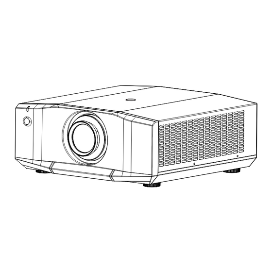
Page 12: Projector Appearance
Overview Projector Appearance Main unit ① ② ⑥ ⑦ ③ ⑫ ④ ⑫ ⑤ ⑫ ⑧ ⑨ ⑫ ⑩ ⑫ ⑪ ⑫ ① LED state indicator ⑦ Control panel ② Lens lock ⑧ Power switch ③ Infrared receiver (front) ⑨... - Page 13 Overview Control panel ③ ⑥ ⑤ AUTO MENU SETUP ① POWER ⑥ ⑥ ⑦ ② ⑧ LENS DOUSER SOURCE ④ ⑥ ① POWER button (power-on/off) Press the power button to enable the projector. In the power-on state, press the power button twice to power off the projector.
-
Page 14: Remote Control
Overview Remote Control ① Power button In standby mode, if you press this key, the device is powered on; in power-on mode, if you press ① ⑨ this key, the screen prompts for the power-off ID SET operation. Press the power button to shut down Lens the device. -
Page 15: Replacing The Battery Of The Remote Control
Overview Replacing the Battery of the Remote Control Procedure Place the remote control with the back facing up, and open the battery cover. ① Put the new battery to the battery compartment. Ensure that the polarity (+ and -) of two AAA batteries are correctly connected to the connectors in the battery compartment. -
Page 16: Installation
Installation Removing the Lens Before replacing the lens, adjust the lens to the center. As shown in the figure, press the lens lock switch on the top cover, and rotate the lens counterclockwise for about 30º. Hold the lens, and move forward to take out the lens. -
Page 17: Installation
Installation Connecting the Projector Connect the projector to the PC or laptop computer. ① Power cable ② RS232 cable ③ HDMI cable ④ VGA cable ② ③ ④ ① Connecting to the socket Connecting to the video device ①... -
Page 18: Powering On/Off The Projector
Installation Powering On/Off the Projector Powering on the projector Ensure that the power cable and signal cable are securely connected. Turn on the power switch and wait until the state LED indicator is steady on red. Press the power button on the remote control or control panel to start up the projector. The state LED indicator is on green, and the screen displays "No signal". -
Page 19: Adjusting The Projected Picture
±20% +80%/-50% AL-FH550/FH650/FH750 ±20% +89%/-56% AL-FX550/FX650/FX750 ±20% +69%/-44% H: Horizontal offset range of the picture when the lens is centered. V: Vertical offset range of the picture when the lens is centered. The values in the table above are approximate and may differ slightly from the actual values. The actual values shall apply. - Page 20 Installation Schematic diagram of vertical offset when the lens is centered. The above table describes the vertical offset ranges (V1/V2) when the lens in different models. Lens center 100% 镜头中心 Projector screen 投影屏幕 Schematic diagram of horizontal offset when the lens is centered Lens center 镜头中心...
-
Page 21: Ceiling-Mounted Installation
Installation Ceiling-mounted Installation Ensure that the screws used secure the mounting bracket meet the following specifications: Screw type: M6*16 Assembly dimension: Unit: mm 135,5 200,0 28,3 131,3 366,0 456,3 200,0 4-M6x16 49,5 356,0 Reserved safety rope nut/Z Caution - If the projector is damaged due to improper installation, the warranty becomes invalid. -
Page 24: Settings
3D SETTING 3D FORMAT 3D DISPLAY DLP LINK L/R EYE FLIP >... -
Page 32: Fault Handling
Fault Handling Troubleshooting The projector fails to power on. Cause Solution Insert one end of the power cable to the AC port on the projector, and insert the The power cable other end to the electrical outlet. If the electrical outlet has a switch, ensure that supplies no power. -
Page 33: Indicator
Fault Handling Indicator Light Status Green Course light Power-off Standby mode Power-on state Blinking Protection state upon safety switch anomalies Blinking Blinking Protection state upon running anomalies System protection ● ﹣ Color wheel failed to be enabled (SN 1) ● ● ● ﹣... - Page 34 Fault Handling ● ● ● ﹣ Power temperature alarm (SN 17) ● ● ﹣ ﹣ DLP anomaly (SN 18) ● ﹣ ﹣ ﹣ PCB DIP switch error (SN 19) ﹣ ﹣ ﹣ ﹣ Power failure (no 12 V output) (SN 20) Caution ●...
-
Page 35: Maintenance And Repair Services
Maintenance and Repair Services Projector Maintenance The projector needs to be maintained. You need to regularly clean the lens. Do not disassemble any parts of the projector. To replace the parts, please contact the dealer. Cleaning the Lens You can clean the lens when you find that the lens surface is stained or dusty. ... -
Page 36: Device Dimensions
Device Dimensions Projector Dimensions Unit: mm 180,0 455,0 456,3 Caution - Be sure to use screws with the correct size. The length of the screw depends on the thickness of the lifting plate. - Be sure to leave a gap of at least 10 cm between the ceiling and the bottom of the projector. - Do not install the projector near heat sources. - Page 37 Appotronics USA, Inc. Address: 1607 McCarthy Blvd, Milpitas, CA 95035 Website: www.appotronicsusa.com P/N: D07000000185 Version: Rev02 Implemented corporate standards: Q/GF 001-2016...
Need help?
Do you have a question about the AL-FX550 and is the answer not in the manual?
Questions and answers