Table of Contents
Advertisement
Quick Links
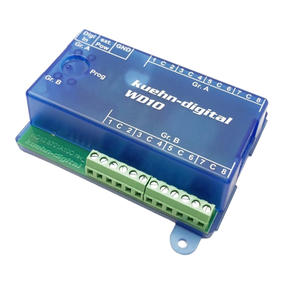
Manual WD10
The switch decoder WD10 is used to switch points (twin solenoid), signals,
uncouplers, light signals (two or more lights), lighting and other consumers. The
WD10 is a multi-protocol decoder and can be used with controllers that support
the Märklin-Motorola-format (e.g. 6021), and DCC controllers (e.g. Lenz, Multi-
maus)
Technical data and features:
• in DCC-format 2044 addresses
• in Motorola-format 320 addresses
• in total 16 transistor outputs (e.g. for 8 points or block signals)
• RailCom® (bidirectional communication, only in use with DCC
• Power from the digital controller or external AC or DC power unit
• simple choice of address and operation mode by internal programming button
• programmable on the program track of the DCC controller
• programmable in built-in state through programming on the main
• selectable light (shadowing) effects for light signals
• minimal power
• maximum power (AC)
• maximum power (pure DC)
• maximum current per switch output
• maximum current per output group (group A or B)
• maximum total current
• working temperature
• measurements (in mm, without assembly points)
Important note: The decoder is only provided for use in model railway layouts in
dry rooms. The use of the decoder is only permitted under supervision. The extra
power supply has to be a model railway transformer, that will switch of by a short
circuit to prevent fire. The connection of the decoder is only allowed in powerless
mode.
NMRA-DCC/Motorola
Universal
Switch decoder WD10
1
12 V
16 V
24 V
1,0 A
1,0 A
1,8 A
0 to 60°C
ca. 83 x 60 x 25
kuehn
Advertisement
Table of Contents

Summary of Contents for Kuehn WD10
- Page 1 The switch decoder WD10 is used to switch points (twin solenoid), signals, uncouplers, light signals (two or more lights), lighting and other consumers. The WD10 is a multi-protocol decoder and can be used with controllers that support the Märklin-Motorola-format (e.g. 6021), and DCC controllers (e.g. Lenz, Multi-...
-
Page 2: Table Of Contents
ManualWD10 Content Safety measurements ................2 Functions of the switch decoder WD10............3 2.1. Digital formats..................... 3 2.2. Switch outputs..................... 3 2.3. Power......................3 2.4. Operation ..................... 3 2.5. RailCom®..................... 3 Installation of the decoder.................4 3.1. Connections and controls................4 3.2. Power from the digital controller............... 4 3.3. -
Page 3: Functions Of The Switch Decoder Wd10
2.4. Operation The switch decoder WD10 supports two setting procedures by the user. On the one hand, the decoder address and the mode (e.g. points, light signals, lighting) can be set for each output group by the programming button. -
Page 4: Installation Of The Decoder
By many consumers that need a lot of energy an external power supply for the switch decoder is recommended. This prevents the use of „expensive” digital current. Use only suitable power supplies (e.g. model railway transformers). The decoder will receive the switch commands of the digital controller through the kuehn... -
Page 5: Connection Of Consumers
. Hint: Connecting the GND-connections on the power is not allowed and can cause damage of the WD10! 3.4. Connection of consumers You can connect different consumers to the switch decoder. Both the output groups A and B behave identically. -
Page 6: Decoder Settings
4.2. Operation modes of the switch decoder The switch decoder WD10 can for the most used applications very easily be set by the selection of operation modes. If you want to make additional adjustments for your desired performance, set the user-mode (mode 1). -
Page 7: Set Up By Programming Button
Manual WD10 Mode Description Similar to User mode: All settings can be done through the configuration register, e.g. changing switch times, operate barriers and barrier lights, etc. 4 output pairs on pulse output, Lenz output remains active according the timer settings... - Page 8 A the LED of group A and the LED of group B will illuminate for approximately 3 seconds. 4. On the WD10 the LED of group B illuminates and the decoder is waiting for the input of the decoder address. Select on your digital controller the point number, which you want to operate with the first output of group B of the WD10.
-
Page 9: Set Up By Dcc-Programming
4.4. Set up by DCC-programming The kuehn – decoder WD10 can be adjusted to the desired performance by programming the so called configuration variables (CV’s). Follow the instructions in the manual of your digital controller during DCC programming. Programming on the program track can be performed by Physical Register Addressing, Paged CV Addressing or Direct Mode Addressing. -
Page 10: Reset The Decoder
Fade down time 0…15 CV#54 CV#55 Fade up time 0…15 CV#56 Dimmer brightness 0...15 CV#57 Operation mode group A 1...8 CV#58 Operation mode group B 1...8 CV#59 Timer output 1,2 group B 0...255 CV#60 Timer output 3,4 group B 0...255 kuehn... -
Page 11: Description Of The Configuration Register
Manual WD10 CV-nr. Meaning Value Factory Your value value CV#61 Timer output 5,6 group B 0...255 CV#62 Timer output 7,8 group B 0...255 CV#63 Speed chase light 0…255 CV#64 Flash & Strobe speed 0…255 CV#127 Sub version software >=1 CV#128 Effect output 1, group A 0...255... - Page 12 • CV#5 Timer for output 5, 6 of group A : description see CV#3 • CV#6 Timer for output 7, 8 of group A : description see CV#3 • CV#7,8 : Here you will find the manufacturer number (kuehn – decoder always have the number 157) and the version number of the decoder.
- Page 13 Manual WD10 • CV#35, CV#36 Decoder address group B: the decoder address of group B is stored in two parts. The decoder address is valid for 4 consecutive point addresses. If the decoder should switch with group 1 the points 1, 2, 3 and 4 enter as decoder address a 1 in CV#35 for the point address 5, 6, 7 and 8 a 2 has to be entered in CV#35 etc..
- Page 14 CV#144 to 159. Example: The first point of group A is switched by two pushbuttons and the outputs 1 and 2 of the WD10 are used. Through the numerical values 1+2=3 in the CV’s 160 and 161 the corresponding assignment of the control command on the used outputs will be carried out.
-
Page 15: Troubleshooting
128 64 5. Troubleshooting Reset: The switch decoder WD10 can be put to the factory settings through the programming button on the decoder or through DCC programming with the digital controller. (default values). • Reset with the programming button: press the programming button with power switched on until the LED of group A and the LED of group B will light up permanently and simultaneously. -
Page 16: Application Notes
Connecting LED If you use LED equipped light signals, a series resistor is required for operation with the WD10 to limit the current. Operation without a series resistor will damage the LED! Check your signal if this series resistor is already installed. -
Page 17: Connecting Light Signals Of The Dr, Db, Öbb, Sbb
Connecting light signals of the DR, DB, ÖBB, SBB DB – light signals Set the used output group of the decoder WD10 tot the operating mode „light signals with max 4 signal images“ (operation mode 7). You can connect 2 light signals with maximal 4 lights each to this output group. - Page 18 Suitable diodes are the switching diodes, for example, 1N4148. ÖBB – Light signals Set the used output group of the decoder WD10 to the operating mode „light signals with max 4 lights“ (operation mode 7). You can connect 2 light signals with maximal 4 lights each to this output group.
- Page 19 Manual WD10 SBB – Light signals type L Set the used output group of the decoder WD10 to the operating mode „light signals with max 4 lights“ (operation mode 7). You can connect 2 light signals with maximal 4 lights each to this output group. Signal 1 is connected to the connectors 1 to 4 and signal 2 to the connectors 5 to 8.
-
Page 20: Connecting Light Signals Of The Ns
6.4. Connecting light signals of the NS Set the used output group of the decoder WD10 tot the operating mode „light signals with max 4 signal images“ (operation mode 8). You can connect 2 light signals with maximal 4 lights each to this output group. Signal 1 is connected to the connectors 1 to 4 and signal 2 to the connectors 5 to 8. -
Page 21: Create Light Signal Images Yourself
Manual WD10 6.5. Create light signal images yourself In user mode (mode 1) you can specify using the CVs 160 to 175, which outputs of the decoder are used by a certain command (validity mask). In the CVs 144 to 159 you can set the switch status of the outputs for the respective commands (ON or OFF). -
Page 22: Warranty
Sending in the decoder has to include your sales receipt or invoice, otherwise there is no guaranty. kuehn... - Page 23 Manual WD10 Märklin® is a registered trademark of the Gebr. Märklin & Cie. GmbH, Göppingen RailCom® is a registered trademark of Lenz Elektronik GmbH, Gießen This product is not to be disposed at the end of its useful live through normal household waste.
Need help?
Do you have a question about the WD10 and is the answer not in the manual?
Questions and answers