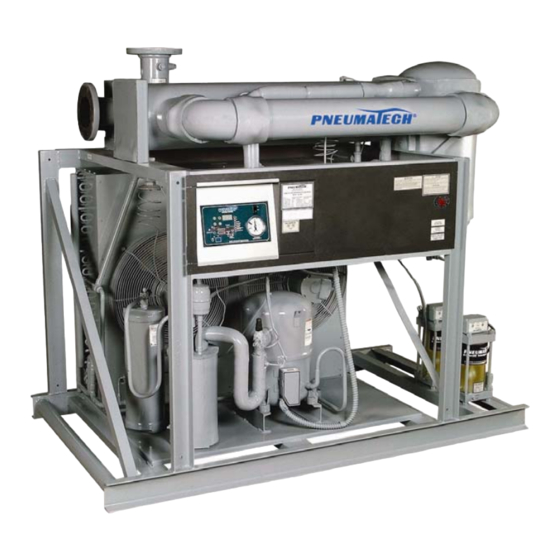
Summary of Contents for Pneumatech AD Series
- Page 1 Noncycling Refrigerated Air Dryers AD-750 to 4000 Series Owner’s Manual 9829 2103 73 August 2009...
- Page 2 DATE OF PURCHASE MODEL SERIAL NO. Record above information from nameplate. Retain this information for future reference.
-
Page 3: Table Of Contents
TABLE OF CONTENTS General Information ......................3 Inspection ......................3 Safety Instructions .....................3 Disclaimer of Warranty..................3 Installation Instructions ....................4 Start-Up and Operation....................7 Design Conditions....................7 Start-Up Procedure ....................7 Operating Range and Control Settings ..............8 Digital Dry Guard™ (DDG) Controller Operation ..........9 Shutdown Procedure ..................10 Operating Conditions ..................10 Maintenance .........................11 Air Dryer Maintenance ..................10... -
Page 4: General Information
GENERAL INFORMATION The Pneumatech Air Drying System is designed to cool 3. USE SUITABLE PARTS & ACCESSORIES and remove moisture from compressed air. When Do not use air pressurized accessories or parts in properly installed, the unit requires little maintenance or the air system not suitable for the maximum air adjustment. -
Page 5: Installation Instructions
INSTALLATION INSTRUCTIONS FIGURE 1 — COMPRESSED AIR SYSTEMS RECOMMENDED INSTALLATION FLOW DIAGRAM... - Page 6 A. Install the dryer INDOORS in an area where the F. For models AD-750 through AD-3200, electronic ambient temperature will be above 55°F (13°C) and timer operated drains are standard. All dryers below 100°F (38°C). Temperatures below 55°F include a particle strainer upstream from the drain (13°C) and above 100°F (38°C) may cause erratic valve.
- Page 7 H. Connect electric power, according to the wiring CAUTION diagram and nameplate power requirements, to the electrical terminals. The refrigerated dryer is designed to run continuously; therefore, it must be SCROLL COMPRESSOR wired separately from the air compressor cycling Air dryers with a scroll compressor are switch.
-
Page 8: Start-Up And Operation
START-UP AND OPERATION The non-cycling design of the refrigerated dryer assures CAUTION proper dew point control at all load conditions. The refrigerant compressor runs continuously when the dryer is “ON”. All dryers are installed with fan cycling switches. STARTING THE DRYER WITHOUT ENERGIZING THE These fans will cycle with respect to the load changes, CRANKCASE HEATER WILL CAUSE PREMATURE ambient temperature fluctuations, and the cleanliness of... -
Page 9: Operating Range And Control Settings
If any malfunction is noticed on the Cut In 280 PSIG expansion valve, contact the factory or your Pneumatech distributor. Fan Control #2: Cut Out 225 PSIG 8. Allow 10 to 15 minutes of cool down time before Cut In 295 PSIG adding the compressed air load. -
Page 10: Digital Dry Guard™ (Ddg) Controller Operation
Setting Drain ON TIME and OFF TIME: DIGITAL DRY GUARD™ (DDG) 1. Press the UP (↑) or DOWN (↓) arrow keys until the CONTROLLER OPERATION LED indicates that ON TIME or OFF TIME has been selected. 2. Press SELECT momentarily (if unlocked) or hold until the display starts flashing (if locked). -
Page 11: Shutdown Procedure
The reasons can “Service Due” indicates the dryer is due for routine maintenance. Please read the maintenance section or contact your Pneumatech dealer. In SERVICE DUE • Low suction pressure mode, several functions relating to the accumulated run •... -
Page 12: Maintenance
MAINTENANCE To back-flush, disconnect air dryer, plug the drain line AIR DRYER MAINTENANCE and fill the air system with the detergent water solution. Hold it for 4-6 hours. Circulate the detergent from air The dryer is factory tested before shipping. All controls outlet to air inlet with a pump. - Page 13 Drain Valve Clean Up Procedure Recommended Operation and A. Depressurize the drain valve. Maintenance for the Particle Strainer B. Disconnect the power source. The particle strainer should be cleaned once every week C. Remove the valve from the compressed air system. or as needed.
-
Page 14: Compressor
COMPRESSOR HOT GAS BYPASS VALVE Refrigerant compressors normally do not need any These air dryers come equipped with modulating hot gas maintenance. The compressor will unload or adjust for bypass valves. This valve maintains the refrigerant different load conditions with the refrigeration controls. suction pressure in varying load conditions. - Page 15 FIGURE 6 — FLOW DIAGRAM AD-750 to 1000...
- Page 16 FIGURE 7 — FLOW DIAGRAM AD-1200 to 2000...
- Page 17 FIGURE 8 — FLOW DIAGRAM AD-2500 to 4000...
-
Page 18: Refrigerated Air Dryer Service Checklist
REFRIGERATED AIR DRYER SERVICE CHECKLIST Please get answers to as many questions as you can before writing or calling for service. 1. Customer’s Name ______________________________________________________________________________ Phone no. ________________________________ Fax no. ____________________________________________ 2. Model no. ________________________________ Serial no. __________________________________________ Voltage L1 _____________ L2 _______________ L3 ______________ PH _____________ HZ ______________ Amp draw L1 ________________________ L2 _________________________ L3 _________________________ Actual air flow (SCFM) _________________________ HP ____________________________________________ 3. -
Page 19: Troubleshooting
TROUBLESHOOTING The following conditions can cause abnormal operation or malfunction of the air dryer • High inlet air temperatures • Low inlet air pressures • High cooling water inlet temperatures • Contaminated cooling water • Untreated cooling water • Condenser water pressure below 35 PSIG •... - Page 20 Table 1 — Troubleshooting Guide, continued Symptoms Cause Remedy D. Compressor starts and runs – 1. Low voltage, or phase unbalance. Check voltage to be within ±10% short cycles on overload. of voltage listed on name plate. 2. Additional current going through Check wiring diagram, check for overload.
- Page 21 Table 1 — Troubleshooting Guide, continued Symptoms Cause Remedy M. Unit runs but air temperature is 1. Refrigerant leak. Locate with leak detector. Repair high. or replace defective part. 2. Evaporator controls set too high. Refer to K – above. NOTE: Outlet air temperature gauge 3.
- Page 24 Pneumatech 4909 70 Avenue Kenosha, WI 53144 Phone: 262-658-4300 Fax: 262-658-1945 www.pneumatech.com...


Need help?
Do you have a question about the AD Series and is the answer not in the manual?
Questions and answers