Advertisement
Available languages
Available languages
Quick Links
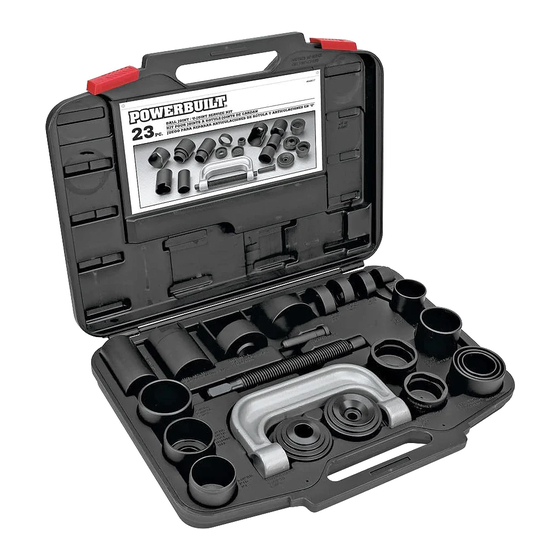
MASTER BALL JOINT SERVICE KIT
Operating Instructions
Ball Joint Removal and Installation
This tool set is designed for use on all cars and light trucks that have
press-fit type ball joints. It will help the user remove and install ball joints
without the need to remove the control arm from the vehicle.
NOTE: Some cars and light trucks may have the upper ball joint spot-
welded to the control arm. The weld must be cut before attempting to
remove the ball joint.
Removal
1. Assemble the ball joint press over the control arm as shown in Figure
3. Select the correct size receiving tube, and position it under the
vehicle ball joint as shown.
2. Tighten the forcing screw until the receiving tube contacts the control
arm. Check alignment of all tooling and components, and continue
tightening the forcing screw until the ball joint is removed.
Installation
1. Clean the control arm and coat the I.D. with a suitable lubricant.
2. Insert the replacement ball joint as straight as possible into the vehicle
control arm.
3. Assemble the ball joint press components as shown in Figure 4.
Position the receiving tube, and tighten the forcing screw. Check the
alignment of all tooling and components, and continue tightening the
forcing screw until the ball joint is firmly seated.
Installing Adapter
Ball Joint
Control
Arm
Receiving
Tube
Removing
Figure 3
Adapter
Installing Adapter
Receiving
Tube
Control
Arm
Ball Joint
Removing
Adapter
Figure 4
Brake Anchor Pin Removal and
Installation
1. Remove all lock ring retainers from the brake
anchor pins.
2. Position the C-frame press over the brake
spider as shown in Figure 1.
3. Tighten the forcing screw until the anchor pin
is removed.
"U" Joint Assembly and
Disassembly
The basic C-frame press is used to service the "U" joints
on most cars and light trucks. The "U" joints can be
serviced either on or off the vehicle.
Disassembly
1. Remove any external and/or internal lock rings.
2. Position the C-frame press around the drive shaft yoke,
and tighten the forcing screw until the first bearing is
removed.
3. Reposition the C-frame and remove the second bearing.
Assembly
1. Clean all dirt and oil from the yoke area.
2. Align the replacement bearing and C-frame press as
straight as possible over the yoke. Press the
replacement bearing into the yoke, and reassemble the
external/internal lock ring.
3. Reposition the C-frame press and second replacement
bearing as straight as possible over the yoke, and press
the bearing into the yoke. Reassemble external/internal
lock ring.
940579
Figure 1
Figure 2
1431 Via Plata, Long Beach, CA 90810-1462
www.powerbuilttools.com
Made in/Fabriqué en/Hecho en Taiwan
© 2009, Powerbuilt Inc. Rev.1
Advertisement

Related Manuals for Powerbuilt MASTER BALL JOINT SERVICE KIT


Summary of Contents for Powerbuilt MASTER BALL JOINT SERVICE KIT
-
Page 1: Operating Instructions
940579 Brake Anchor Pin Removal and MASTER BALL JOINT SERVICE KIT Installation Installing Adapter Operating Instructions 1. Remove all lock ring retainers from the brake anchor pins. 2. Position the C-frame press over the brake Ball Joint spider as shown in Figure 1. - Page 2 940579 Dépose et installation de l’axe de segment de frein NÉCESSAIRE COMPLET DE RÉPARATION 1. Retirer tous les arrêtoirs sur les anneaux verrouilleurs des axes de segments Adaptateur de frein. POUR JOINTS À ROTULE d’installation 2. Positionner la presse en C sur le porte-segments de frein comme illustré...
- Page 3 940579 Retiro e instalación de la clavija de anclaje del freno JUEGO DE SERVICIO PARA JUNTAS 1. Retire de las clavijas de anclaje del freno todos los retenes del anillo de seguridad. Adaptador de ESFÉRICAS MAESTRAS 2. Coloque la prensa en C sobre la araña del freno tal como instalación se muestra en la Figura 1.
Need help?
Do you have a question about the MASTER BALL JOINT SERVICE KIT and is the answer not in the manual?
Questions and answers