Table of Contents
Advertisement
Advertisement
Table of Contents

Subscribe to Our Youtube Channel
Summary of Contents for Galcon Gal 2 Way
- Page 1 G2W – Gal 2 Way Installation and Operation Instructions Version 1.0 July 2012...
- Page 2 G2W – Gal 2 Way – Installation and Operation Guide About this Manual This manual contains important information about the system components, installation process, and operation protocols of the Gal2Way system. Make sure to carefully read all of the information contained in this manual and keep this manual in a safe place for future reference as necessary.
-
Page 3: Table Of Contents
Introduction .......................... 7 Technical Overview ........................7 System Components ......................9 Field Units ..........................9 Galcon RTU Field Unit Features ..................9 G2W4 and G2W8 Field Unit Features ................10 Field Units Power Supply ....................11 Field Units Connection ....................11 Repeater (Relay) ........................ - Page 4 G2W – Gal 2 Way – Installation and Operation Guide Operating Gal2Way 4 and Gal2Way 8 Field Units ..............35 Viewing the Communication Status and Serial Number ..............35 Viewing the Galileo ID Number ....................35 Viewing the Battery Status ....................... 35 Testing Output Ports ........................
- Page 5 G2W – Gal 2 Way – Installation and Operation Guide List of Figures Figure 1: Galcon 8489 RTU Features ....................10 Figure 2: G2W 4 / G2W 8 Features ....................10 Figure 3: Concentrator Main Features ....................12 Figure 4: Radio INT Card Components ....................13 Figure 5: Concentrator Buttons ......................
-
Page 7: Introduction
Galileo controller, utilizing latch outputs, as well as analog and discrete inputs. The Gal2Way system is another great addition to the Galcon Ag line of products. Technical Overview The G2W system consists of the following components: Galileo Controller Concentrator. -
Page 9: System Components
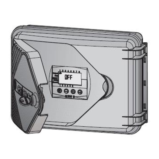
100%. The Ingress Protection of the field units is IP54. Galcon RTU Field Unit Features The Galcon RTU field units have the flowing input and output ports: 4 x 3 wire DC latch output ports. -
Page 10: G2W4 And G2W8 Field Unit Features
G2W – Gal 2 Way – Installation and Operation Guide Battery compartment. Analog input ports (4-20 mA / 0-10 V). III. 6 X Discrete input ports. 3 X Wire 18 V DC Latch output ports. Galcon RTU card as IO card. -
Page 11: Field Units Power Supply
Contact Galcon to request these alternative components. Note: Galcon RTU field units do not supply power to the connected sensors. When connecting sensors to the analog inputs or when transmitting data to the digital inputs you must supply an external source of power for them. -
Page 12: Concentrator Connections
G2W – Gal 2 Way – Installation and Operation Guide The concentrator can be installed in one of two ways: Installed close to the controller, at a distance of not more than 10 meters, using direct communication (RS-232). Installed at a distance of not more than 30 meters, using an RS-485 adaptor. -
Page 13: Radio Int Adaptor Card Main Features
G2W – Gal 2 Way – Installation and Operation Guide Radio INT Adaptor Card Main Features Figure 4: Radio INT Card Components LED indicators for normal card operation. II. LED indicators for communication with the CPU. III. LED indicators for communication with the concentrator. -
Page 15: Registering System Components
3 Registering System Components All the field units and repeaters in the system need to be registered in the concentrator. This registration process is performed on the concentrator; there is no need for any registration process on the controller. Connecting or disconnecting the controller will not affect the registration process. Notes: ... -
Page 16: Registering Repeaters
G2W – Gal 2 Way – Installation and Operation Guide d. Press until “ADD NEW DEVICES” is displayed on the screen, and press to select it. The message “ENROLL NOW or ENTER ID XX-XXXX” flashes on the screen. On the field unit you are registering, hold down the registration button (see Figure 1 or Figure 2) until the red LED turns on. -
Page 17: Viewing The List Of Registered Field Units And Repeaters
G2W – Gal 2 Way – Installation and Operation Guide c. Repeat steps 1 through 3 to register an additional repeater unit. Repeat these sub-steps until you have registered all the repeater units. 5. After you have registered all the repeater units, press to end the registration process and exit to the main menu. -
Page 19: Installing The G2W System
4 Installing the G2W System Pre-Installation Planning Before installing the components of the Gal2Way system, make sure to examine the installation environment to determine the best locations for installation. You must make sure to install components above obstructions which may interfere with the RF transmissions between components. -
Page 20: Connecting The Concentrator To An External Power Supply
G2W – Gal 2 Way – Installation and Operation Guide Note: The concentrator should be located within shelter for direct, initial Protection from effects of the weather Figure 6: Installing the Concentrator Connecting the Concentrator to an External Power Supply... -
Page 21: Connecting The Concentrator To The Controller Via Rs-232 Connections
To connect the concentrator to the controller: 1. Connect one end of the eight-wire communication cable to the Radio INT adaptor card, located in the controller. Connect the wire’s other end to the Galcon Galcel (AI0617) connector. 2. Connect the Galcel connector to the communication adaptor. -
Page 22: Installing Repeaters
G2W – Gal 2 Way – Installation and Operation Guide Position the unit so that its cable inputs are positioned downward. Position the antenna at least 2 meters above the ground. To install a field unit: 1. Install the field unit in one of the following ways: Affix the unit to any vertical surface by means of screws, inserted through the holes in the aluminum plate at the back of the unit box (Figure 9). - Page 23 G2W – Gal 2 Way – Installation and Operation Guide To install the repeater: 1. Install the repeater in one of the following ways: Affix to any vertical surface by inserting screws through the holes in the aluminum plate at the back of the unit box.
-
Page 25: Performing Communications Diagnostics Tests
5 Performing Communications Diagnostics Tests The communications diagnostics test is used to test the communication strength between the concentrator and each registered field unit or repeater. You can perform this test for all units simultaneously (from the concentrator), or for one unit at a time (either from the concentrator or from each unit itself). -
Page 26: Performing The Communications Diagnostics Test For One Field Unit Or Repeater From The Concentrator
G2W – Gal 2 Way – Installation and Operation Guide Performing the Communications Diagnostics Test for One Field Unit or Repeater from the Concentrator To perform the communications diagnostics test for one field unit from the concentrator: 1. Press until “INSTALLER MENU” is displayed on the screen, and press to select it. -
Page 27: Performing The Communications Diagnostics Test From One Field Unit Or Repeater
G2W – Gal 2 Way – Installation and Operation Guide Performing the Communications Diagnostics Test from One Field Unit or Repeater Note: Performing communications diagnostic tests from a field unit or repeater requires that you open the field unit and access the registration button on its circuit board. -
Page 28: Viewing Communications Strength From The Controller
G2W – Gal 2 Way – Installation and Operation Guide Viewing Communications Strength from the Controller When enabled, the controller displays the communication strength between the concentrator and field units in its “current value” row. The communication strength value displayed by the controller ranges between 0 and 255, with 255 being the strongest value. - Page 29 G2W – Gal 2 Way – Installation and Operation Guide 5. For the fourth input of each field unit, define the following input settings: In the Sensor Type row, enter 0-10 V. In the Min. Value row, enter 0. In the Max. Value row, enter 255.
-
Page 31: Configuring Field Units And Repeaters
6 Configuring Field Units and Repeaters All field units and repeater units have various configurable parameters. When registering a unit with the concentrator, the unit receives its default setting definitions from those defined for the concentrator. You can redefine the concentrator settings before registration to automatically upload the modified settings to the units upon registration. -
Page 32: Modifying The Configuration Settings For Individual Field Units From The Concentrator
G2W – Gal 2 Way – Installation and Operation Guide 8. Press to exit to the main menu, and press to confirm. The message “DEV UPDATING” is displayed on the screen. The concentrator emits four beeps and returns to the main display screen. - Page 33 G2W – Gal 2 Way – Installation and Operation Guide 2. Enter technician code 9999. The concentrator emits four beeps and requests confirmation. Do not change the technician code. 3. Press until “DEVICES” is displayed on the screen, and press to select it.
-
Page 35: Operating Gal2Way 4 And Gal2Way 8 Field Units
7 Operating Gal2Way 4 and Gal2Way 8 Field Units In addition to the Galcon RTU field unit type, the G2W system supports the following second-generation field unit types: Gal2Way 4 and Gal2Way 8. These field units have four or eight output connectors respectively. -
Page 36: Testing Output Ports
G2W – Gal 2 Way – Installation and Operation Guide Testing Output Ports In order to test the field unit’s output ports, perform the following test to each port. To test output ports: 1. Press . The main screen is displayed. -
Page 37: Converting The Galileo Controller To The G2W System
8 Converting the Galileo Controller to the G2W System Converting the Galileo controller to the G2W system involves installing one or two Radio INT adaptor cards, and configuring the Galileo controller to enable recognition of radio field units and repeaters. This is achieved by defining the number of radio units will be added to the system, and assigning adaptor card slots to them. -
Page 38: Assigning Adaptor Card Slots For Field Units In The System
G2W – Gal 2 Way – Installation and Operation Guide Figure 12: Maximum Active Elements Definition Window 3. Click the key symbol. 4. In the Max. Active Wire RTU Number (0-128) row, enter the total number of field units and repeaters, both cable and radio, that are to be registered in the system. -
Page 39: Figure 13: Rtu Definition Window
G2W – Gal 2 Way – Installation and Operation Guide Figure 13: RTU Definition Window 3. Click the key symbol. 4. In the RTU Connection Setup area, select ports for allotment to field units according to the calculation that each field unit requires one controller port for every two field unit output ports. -
Page 41: A Safety Instructions For Installing Antennas
A Safety Instructions for Installing Antennas Do not climb on the antenna pole. In order to lower/raise the antenna for maintenance operations, remove one of the anchoring screws and lower the antenna and axis to the floor. Do not set up antennas near high voltage lines. Make sure that the base of each antenna is properly positioned and affixed to the concrete floor. - Page 42 Limited Warranty Certificate 1. Galcon shall, for a limited period of 12 months from the retail purchase date of the original (first) purchaser (“the Warranty Period”), provide limited warranty for the Products, as provided for and subject to the provisions and limitations of this Limited Warranty Certificate.
- Page 43 Galcon’s property. 8. Galcon reserves the right to charge the Customer if any warranty service is requested and carried out but no fault is found in the Product or if such defect/fault is not under Galcon’s Warranty.
Need help?
Do you have a question about the Gal 2 Way and is the answer not in the manual?
Questions and answers