Advertisement
Quick Links
Advertisement

Subscribe to Our Youtube Channel
Summary of Contents for SAelen TS GS/PUMA 35D
-
Page 4: Declaration Of Conformity
DECLARATION OF CONFORMITY TS industrie LA SOCIETE Weserstrasse 2 47506 NEUKIRCHEN-VLUYN Tél : +49(0)2845 9292-0 Fax : +49(0)2845 9292-28 HEREBY DECLARE THAT THE MACHINE: TS Industrie Trade Name: Type : GS/PUMA35D Engine performance: 26,2 kW Technical documentation held by Mathieu Willerval. is in conformity with the following European Directives: - 2006/42/EC Directive „Machinery“... - Page 5 Before our machines are delivered they pass a tight quality control in the works Given that we no longer have a bearing on the machine after it leaves the works, the dealer has to perform another check before the delivery to the end customer The following is to be checked Exterior damages produced by transport etc Tight seat of all screw and hose connections...
-
Page 6: Processing Of Warranty Claims
Processing of warranty claims Warranty claims according to the General Business Terms of the manufacturer are valid for the period of 1 year starting with the day of delivery. Determinative for the moment of the transfer of risk is the date written in the Machine Delivery Document. - Page 7 PATENT FOR INVENTION Intellectual property law-Books VI GRANTING DECISION The General Manager of the National Institute of industrial property has decided that invention patent # ##-##### the text of which is appended shall be delivered to: SAELEN S.N.S. Company - FR The delivery produces its effects for a period of twenty years starting on the date of deposit of the application, under reserve of payment of the annual royalties.
- Page 8 We thank you very much for deciding to purchase an universal chipper from TS Industrie . In order to meet these requirements also for the mostly professional applications, we kindly ask you to diligently read this operating manual and to comply especially with the warning and maintenance information Only if complying with all maintenance works within the specified maintenance intervals we can concede the full manufacturer’s warranty for your universal chipper from TS Industrie The operating manual includes several models such that in the introduction is explained how to orient...
- Page 9 For any spare parts order or a question regarding technical information have always the serial number of your at hand The serial number is located as shown in the image. It does always have five- or six-digit number.
-
Page 10: Safety Instructions
Safety instructions 1. The machine is only allowed to be used according to the operating manual! 2. In case of machines with engine also the operating instructions of the engine are to be observed. 3. Folding the intake extension up (as far as present) is only allowed after standstill of the rotor. 4. - Page 11 13. For transporting the wood chipper it must be moved into transport position. A) Fold the hopper (as far as present) up and check if the locking device is engaged. B) Move the wood chipper into transport position an check if the safety pin has engaged. C) Turn the ejection channel such that it does not jut laterally out over the machine.
- Page 12 23. Carry out an functional check every day before starting the machine, especially of the safety equipment (trailer coupling, gear linkage, shifting block, cut-off switch on the hoods in case of the M version etc.). Chipping knives and counter-knives are also to be checked for proper functioning and tight seat.
- Page 13 Pic tographs Wear eye and ear protection! Use protective gloves with specially tight gaunt- lets! Wear safety shoes! Do only touch machine parts after they are at a complete standstill! Keep sufficient distance to rotating machine parts!
- Page 14 Pic tographs While the drive is running never open and remove protective devices! Read the operating manual before start-up! Do not stay in the area of the expulsion if the machine is running! Hazard area! Shut down the engine and remove the key prior to any maintenance and repair work! Caution! Entanglement.
- Page 15 The sound level of the working machine is not the value of the standard level on the sticker. MaximumRPM motor Minimum RPM motor Moving direction commands for the conveyor belt Material chipping (forward max. speed) Stopping rotation of the infeed rollers Loosening material (backwards)
-
Page 16: Safe Transport
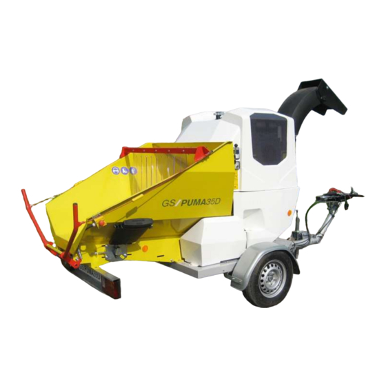
Safe transport Observe the valid Highway Code Ensure that the machine is always fitted with signal lights, which are clean and visible for other road users. Reduce speed when driving on rural roads and unlevel routes Coupling wear indication: Check the wear indication each time the machine is hooked up to the tractor vehicle. - Page 17 General description and functions is designed for chipping branches up to a diameter of 6,30 inchs. The machine consists of the following main components Frame Chipping unit Engine and drives Expulsion chimney Noise insulation hoods...
- Page 18 General description and functions The frame is used for allocating the different components of the chipper The unit consists of one infeed hopper (1) . An anti-blocking system disconnects the infeed if the speed of the rotor falls below the minimum speed (chipping unit jammed) and automatically connects again after the speed of the rotor is sufficient for correct chipping work The infeed can turn into both directions (forward and...
- Page 19 General description and functions The diesel engine is located above the chipping unit. It supplies the required energy for the drive of the rotor and the hydraulic oil pump The machine is driven by a 3-cylinder diesel engine with an output of 35 HP at 3000 rpm Further information regarding the engine can be taken from the manual of the manufacturer The rotor is driven via the output shaft, the centrifugal clutch with belt pulley This expulsion channel expulses the chipped material.
- Page 20 General description and functions The PUMA is fitted with an electrically controlled hydraulic distributor, which is acti- vated with two buttons at the rear of the infeed hopper for running forwards and back- wards, and with a red control rod for disconnection of the infeed roller and the convey- or belt.
- Page 21 When hooking the wood chipper to a vehicle the procedure is as follows. With the support wheel adjust the height of the drawbar such that the trailer coupling is standing above the vehicle. Now reel the support wheel in and the open ball head coupling has to engage on the ball of the trailer coupling Ensure that the trailer coupling safely engages! The wear indication on the coupling must be in the green area...
- Page 22 Operate the machine only with Non-Road fuels or commercially available diesel fuel. In case the machine shows difficulties in chipping the material and has to be switched off, restart the engine only after having removed the cause and the material was removed from the rotor!!! Each time before start-up of the machine ensure that is is standing stable on solid ground.
- Page 23 Watch out for solid foothold of the operating personnel Place chipping material on the hopper bottom and move it with the thicker en (trunk) towards the infeed rollers (chamfer the thick end of the trunk). As soon as the material is captured by the rollers move to the side, because due to unevenness of the trunk there might be material kick-out The captured material now is automatically chipped and hurled into the direction (distance) into which the expulsion chimney was set to beforehand...
- Page 24 Have the chipper run for some minutes empty for removing the residual material behind the infeed roller in the chipper to prevent that the rotor becomes jammed in the next application, and the message For stopping the infeed roller move the control rod forward.
- Page 25 BIODEGRADABLE LUBRICANTS FOR REDUCING ENVIRONMENTAL POLLUTION mulch and wood chips chippers are often used in woods, parks, landmarks, in the proximity of lakes and rivers, where leaks and hydraulic fluids signify a risk for the environment biodegradable high performance lubricants Corresponds to the agricultural Directive 2006/11/EG Increase biodegradability Regenerative...
- Page 26 Securely park the machine, remove the contact key and wait until the standstill of all mobile parts before starting the maintenance and repair works After termination of the maintenance works ensure that all protective devices are properly mounted and are operative All machines pass a test-drive before leaving the works.
-
Page 27: Every Day
- Check tight seat of the adjusting joints front side of the trailer coupling/ Every day drawbar - Check function of the safety switches and the red control rod - Check the engine oil level - Check the coolant level - Check the cleanliness of engine radiator - Check the trailer coupling - Check the tight seat of wheel nuts... - Page 28 nuts...
- Page 31 Window for maximum tension Attention: Avoid infeed of roots with earth still sticking to it. This might accumulate in the front drive roll and block the conveyor belt.
- Page 32 For checking the conveyor belt and the self-lubricating polyethylene plate, completely relax the conveyor belt and lift it with a hook. The following parts have to be checked...
-
Page 33: Maintenance
Maintenance Tool to lock rotor Screwlock knives and hammers: To remove knives and hammers 157 N.m. - Ex works, all 6 fastening screws of knives and inserts secured without screwlock medium, with a torque of 157 Nm (16 M.kg ), and therefore must be loosened using a corresponding tool Unsrew all fastening screws from knives and inserts... - Page 34 Maintenance Also it is to be observed that the edge of the knives is to be sharpened at an angle of 35°. After sharpening, the length A 50 mm ( 60 mm). TCHC 12 X 40 class 12.9 Tightening with the correct torque is important to prevent the screws from coming loose.
- Page 35 - Unscrew retaining screws Ø10 (1) at both ends of the counter-knife. - Unscrew both locking screws Ø8 (2). - Pull the counter-knife partially out of the housing. If the edge is worn, pull the counter-knife out of the housing, give it a quarter turn, such that the new edge is pointing towards the knives, and push the counter -knife back into the housing.
- Page 37 slightly tensioned Correctly retighten locknut...
- Page 39 Green warning light - operating control light (OK9 Warning light battery charge control Warning light oil pressure Warning light coolant temperature Do not put the contact key on a heavy bunch of keys, this might produce disconnection of the ignition during the operation...
- Page 40 Continuous indication of the engine speed Continuous indication of the rotor speed Continuous indication of the daily operating hours Continuous indication the total operating hours Hydraulic test: a fast forward and backward travel speed serves for testing the hydraulic system A fast forward movement of the infeed roller serves for testing the No Stress System 3 No Stress (Vario Stress) Options for choosing the type of wood Service management : Intervals for oil change...
- Page 41 Green - continuous: ON Green - flashing: Pulses from rotor encoder Red - continuous: Engine hood or access to chimney open ↓ ↑ It is strictly prohibited to change the factory settings of the Pilot System. The pro- gramming person is responsible for any change of the parameters outside the works of TS Industrie...
- Page 42 Above each key there is a symbol for the accord- ing setting, showing a black background when se- lecting this setting 1 for wooden waste: Utilises an amplified engine speed : Utilises a medium speed range. Branches and coniferous wood can be processed 3 for coniferous wood and vegetation, e.g.
- Page 43 The indication RPM too low shows that the engine speed is insufficient for continuous material infeed to the rotor Now the yellow button can be activated As soon as the infeed roller is rotating and the rear red control rod is activated, appears the message If the rotor speed is too high, the infeed roll- er is automatically stopped to protect the...
- Page 44 The Pilot System controls the slip between the belt pulleys of rotor and engine by continuous comparison of both speeds. For the protection of V-belts, centrifugal clutch and hydraulic coupling, a slip of one per cent is admissible. If slip increases to over one per cent, the en- gine is shut off and the following messages appears on the display Different reasons for slip Slip can be produced if the machine from standing is accelerated very slowly...
- Page 45 Keep key ↓ and ↑ pressed for Press key ↑ 3 times until the 4 seconds. number 3 is displayed, than con- firm with key 1. Press key 1 again for confirmation Press key 1 for confirmation and go and go to the second 0. to the first 0.
- Page 46 Reset of the daily operating hour counter Press key 1 to confirm deletion of the daily operating hours. Press key ↓ and put the cursor on Daily oper. hrs. The process is indicated with a corresponding message. Press key ↓ and put the cursor on End.
- Page 47 Overdue service and further service information When starting the machine, the system shows a warning message and a corresponding symbol as soon as maintenance is due or overdue. Agree with your dealer a date for an oil change. The message is saved in the Pilot Sys- tem.
- Page 48 Press key ↓ or ↑ once or twice at any time for indication of the rotor speed for the selected NO Stress setting: Example setting 1: Minimum: Speed below 1875 rpm. The infeed roller is disconnected. Return: As from a speed of 2175 rpm. The infeed roller is restarted. Normal: After an overspeed of the engine, the speed of the rotor must be reduced to below 2175 rpm for the infeed roller to reconnect.
- Page 49 An open or incorrectly closed hood is indicated by a red LED an a corresponding mes- sage. The safety system shuts the engine off and impedes a restart. In this case, close the affected hood correctly and then press key 1. The message disappears. Red LED A permanently shining green LED shows that rotor and system are operating.
- Page 51 The machine is fitted with a safeguard for hood and expulsion chimney: This safeguard consists of two proximity sensors. One (1) is located at the front side from the expulsion chimney and the other (2) at the front left side of the engine bracket. The electric switching contact is established when the sensor approaches the magnet (2) on the yellow hood.
- Page 53 One blade-type fuse 40 A is located in the fixture on the battery cable beside the starter motor...
- Page 55 In this chapter we have compiled a list of possible errors, their causes and their solutions. In case an error appears, which is not listed in chapter "Troubleshooting", please contact your dealer. Have your operating manual and the serial number of your machine on hand The engine is shut off and the Pilot System shows the message “Slip error”.
- Page 56 No forward or backward mo- - Loosen the regulating screw Regulating screw at infeed com- pletely screwed down tion of the conveyor belt or of the infeed roller Hydraulic motor or pump defective Oil deficiency in hydraulic tank...
-
Page 57: Specifications
Specifications...
Need help?
Do you have a question about the GS/PUMA 35D and is the answer not in the manual?
Questions and answers