
Related Manuals for Neptune G-50-1

Summary of Contents for Neptune G-50-1
- Page 1 OPERATING & INSTRUCTION MANUAL NEPTUNE GLYCOL FEED SYSTEM Models G-50-1, G-50-1A, G-50-2A, G-100-1A, G-100-2A Lansdale, PA 19446 Tel: 215-699-8700 Fax: 215-699-0370 REV NO 6 – 01/08/04 ZL106838...
-
Page 2: General Description
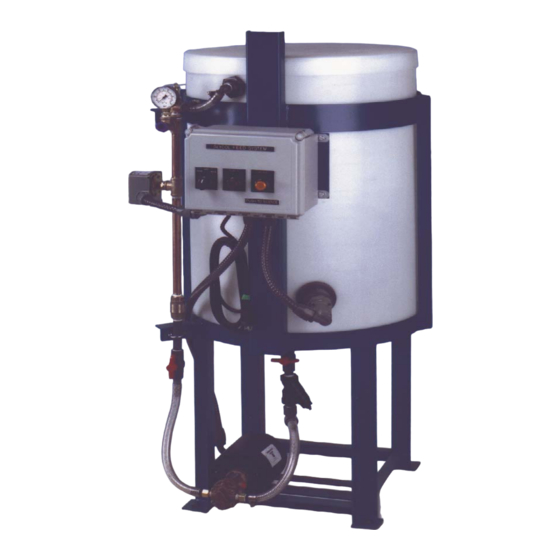
MODELS The Model G-50-1 or G-100-1 is provided with a 50 or 100 gallon polyethylene tank mounted in a steel frame, 1.5 gpm bronze rotary gear pump (optional 3.0 gpm pump), float switch and NEMA 4X control panel. -
Page 3: Please Read This
OPERATION The glycol feeder is provided with a control panel with HAND/OFF/AUTO selector switch. When the panel is switched to the AUTO position, the pump is actuated via the pressure switch, which is mounted in the discharge assembly and sensing the pressure in the loop. The pressure switch is pre-set to start the pump at 12 psi and stop the pump when 30 psi in the loop is achieved. -
Page 4: Troubleshooting
TROUBLESHOOTING PROBLEM PROBABLE CAUSE Pump is running but is 1. The motor rotation is incorrect. The not pumping anything proper rotation of the motor is counter-clockwise when looking at the motor shaft. Check the wiring diagram on the motor or the attached motor diagram for proper wiring. - Page 8 Bronze Rotary Gear Pumps Installation, Operation, and Maintenance Instruction INTRODUCTION Congratulations for choosing an Oberdorfer pump,the Industry Standard for quality since 1890. Construction Bronze Rotary Gear standard pump housings and helical gears are made of top quality bronze. Shafts are stainless steel. Pumps are available with bronze bearings and grease fittings or with carbon bearings which require no lubrication.
-
Page 9: Installation
BRONZE ROTARY GEAR PUMP INSTRUCTIONS continued ……. INSTALLATION Site Preparation Choose a site that allows easy access to the pump for maintenance. Consider protection from the elements. Guard against drips and spray from nearby equipment. Choose a solid foundation for mounting. If noise is a concern, consider a rubber pad under the pump base to dampen. -
Page 10: Operation
BRONZE ROTARY GEAR PUMP INSTRUCTIONS continued ……. Flow By-Pass When a flow by-pass system is used to control output from the pump, the bypassed fluid should be directed back to the suction vessel to avoid recirculation heat build-up. In cases where this is not possible, connect to the suction at least 10 pipe diameters length away from the pump inlet. -
Page 11: Mechanical Seals
Mechanical Seals Pumps equipped with mechanical seals are of the standard pusher bellows type or wedge style. They can be expected to provide long and troublefree service provided: 1) Seal materials are compatible with pumped fluid and properly applied to the service. 2) Adequate cooling and lubrication is provided 3) Dry running is avoided 4) Abrasives are kept away from the seal area... -
Page 12: Technical Terms
PRESSURE SWITCH INSTRUCTIONS SQUARE D Commercial Pressure Switch Class 9013, Model FSG29J99 Model FSG29J99 CUT-OUT RANGE 20-60 PSI ADJUSTABLE RANGE 10-30 PSI CUT-IN RANGE 10-45 PSI PRESSURE CONNECTION : ¼” NPT EXTERNAL ECHNICAL ERMS Operating Points (Settings) Every pressure switch has two operating points; one on rising pressure and one of falling pressure. The operating point on rising pressure is referred to as the TRIP POINT or cut out for pumps and compressors and the operating point on falling pressure is referred to as the RESET POINT or cut in for pumps and compressors. - Page 13 PRESSURE SWITCH INSTRUCTIONS continued ….. SET POINT ADJUSTMENTS The pressure switch is set at the factory to the operating point(s) marked on the outside of the switch housing. Before readjusting the switch, cyle it to determine actual operating points. Non-Adjustable Differential The range adjustment nut ( Item H, Figure 3 ) or knob ( Item C, Figure 3 ) adjusts both setpoints by the same amount.
- Page 14 INSTALLATION INSTRUCTIONS LL-3 (L-30N) LIQUID LEVEL SWITCH MODEL L30N LIQUID LEVEL SWITCH INSTALLATION AND OPERATING INSTRUCTIONS Installation: The L-30 liquid level switch is supplied with a 1-1/2” or 1-1/4” X 1 bushing threaded in place with 2 to 3 wraps of teflon tape, which must be intact or renewed if bushing and switch are separated before assembly in tank.
- Page 15 MODEL L30N LIQUID LEVEL SWITCH INSTALLATION AND OPERATING INSTRUCTIONS 5). Apply slip on terminals to appropriate contacts of micro switch. Slide cover down cable and fasten to body of switch with four screws provided. Slide grommet down cable until outer jacket is level with small end of grommet per illustration page 2. Push grommet into tapered end of cover.
Need help?
Do you have a question about the G-50-1 and is the answer not in the manual?
Questions and answers