
Related Manuals for Simpson S660

Summary of Contents for Simpson S660
- Page 1 S660 Digital Preset / Totalizer Counter Operation Manual 1.800.561.8187 information@itm.com www. .com...
- Page 2 SIMPSON ELECTRIC COMPANY neither assumes nor authorizes any other persons to assume for it any other liability in connection with the sales of its products.
-
Page 3: Table Of Contents
Contents 1 Product Description..........3 1.1 General Description. -
Page 4: Product Description
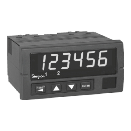
1 Product Description General Description The S660 preset counter fits a 1/8 DIN standard cutout and is perfect for tight spaces, extending only 3.24" (82mm) behind the panel. The unit is UL listed. The unit is for indoor use at altitudes up to 2000m, temperatures between 0°... -
Page 5: Part Number Identification
The following matrix indicates the configuration of your S660 counter. Option Module Summary The S660 is a modular product that uses field configuring slide-in modules. The modules slide easily into the rear of the counter. Figure 1 displays the functional assignments for each module position. -
Page 6: Hardware Setup
2 Hardware Setup Panel Installation The S660 1/8 DIN counter requires a standard 1/8 DIN panel cutout of 1.77" (45mm) high by 3.62" (92mm) wide. To install the counter into a panel cutout, remove the clips from the side of the counter. -
Page 7: Removing / Installing Option Modules
2.2 Removing / Installing Option Modules Shut power off before removing or installing any option modules Couper le courant avant de retirer ou d’installer des modules optionnels 1. Remove module from case by inserting a screwdriver into tab slot opening at top of input module. -
Page 8: 120/240 Vac Power Module
120/240 VAC Power Module Remove power before wiring option modules. Coupez l’alimentation avant de raccorder les modules optionnels. The AC power module allows the S660 to be Denotes modules position 4 at rear operated from standard 50/60 Hz line power. - Page 9 If channel B is not used, default settings for switch positions 1 through 3 should be selected. Default settings are provided in Table 2. The Input module also provides for a user input signal. On the S660, this input serves as a count enable/disable control. Connecting User to Common will disable counting.
- Page 10 5 A Channel Frequency: OFF = Hi* (low pass filter disabled) ON = Lo (low pass filter enabled) 6 A Channel Sensor Type: OFF = Sinking* (internal pull-up enabled) ON = Source (internal pull-down enabled) LOW BIAS HIGH BIAS LOW FREQUENCY HIGH BIAS LOW BIAS HIGH FREQUENCY...
-
Page 11: Quadrature Input Module
The technician is also able to determine the polarity of the user input. The Input module also provides for a User input signal. On the S660, this input serves as a Count Enable/Disable. -
Page 12: Excitation Module
Table 3. Quadrature Module DIP Switch and Jumper Settings JP1/2: Count Mode Selector Jumpered 1-2 = Quadrature mode Jumpered 2-3 = Standard counter mode SW1: 10 Position DIP Switch * = Factory Default setting 1 B Channel Bias: OFF = Hi* VLT = 5.0V VUT = 7.0V (+/- 10%) ON = Low... - Page 13 The Excitation Module can supply 12 VDC at up to 100 mA for external sensors or encoders. This excitation is isolated from the counter internal logic supply. When using sensors or encoders that do not have a signal return or imply a signal return that is in common with the supply voltage, a common attachment that ties the excitation supply to the logic input common may be required.
-
Page 14: Single And Dual Relay Modules
2.7 Single and Dual Relay Modules The Single and Dual Relay modules can activate circuit loads of up to 5 amps at 250 VAC. A Form C configuration allows use of normally-open (NO) and normally-closed (NC) circuit action. Only the output 1 channel is implemented in the single relay module. Figure 14. -
Page 15: Display Error Messages
Display Error Messages Table 4. Display Error Messages . r i l l i s ’ 1.800.561.8187 information@itm.com www. .com... -
Page 16: What The Keys Do In Display Mode
What the Keys Do in Display Mode RESET ENTER The up and down keys navigate through the available menu functions. The menu ‘wraps around’ when the bottom or top of the menu is reached. The up and down key increment or decrement the flashing digit. What the Keys Do in the Programming Mode Select the next digit to the left of the current flashing RESET... - Page 17 Display Mode Figure 17. Programming Menu Structure In the Programming Mode, the S660 will return to Display Mode automatically if a key is not pressed within 120 seconds (2 minutes). The menu is comprised of three levels: Setup Menu, Function Menu and Option Edit Menu. Figure 17 illustrates the three levels of the menu system.
-
Page 18: Special Start-Up Modes
3.5 Special Start up Modes There are two start-up modes for the S660 counter. The default start-up mode will be used every time the counter is powered up by the user. There is one alternate start-up mode that will allow the operator to return the counter software functions to factory default settings. -
Page 19: Programming Operations And Parameters
4 Programming Operations and Parameters This section details the initial programming options of the S660, presuming all defaults are in place. If you are already familiar with the S660 programming, see Appendix B for the Programming Quick Reference Guide. and press S . - Page 20 Table 5. Password Values If a password is already in the counter, the display will flash between pass, for “Enter Password,” and the default value, 000. When the display shows 000, press ENTER . Use the arrow keys to change the flashing digit to the desired number.
-
Page 21: A/B Channel Options
A/B Channel Options (Input Setup) The next category in the Programming Mode is the “Input Setup.” Here you can adjust the A and B channels to the appropriate count modes. The A channel input may be selected as an Up, Down, Quadrature or Reverse Quadrature* input. -
Page 22: Scaling And Decimal Point Position
6-digit capacity might otherwise allow by making the positive count the most significant digit. Generally speaking, the smaller the scale value, the more accurate the count will be. The S660 has four prescale values, 1.0 (default), 0.1, 0.01, and 0.001. - Page 23 Scale. User-defined Scale The S660 also allows for a user-defined scaling multiplier. To access the user-defined scaling parameter, enter the Programming Mode, and press T until the count setup menu category is reached. Press ENTER Press T to continue to the Parameter Name scale.
-
Page 24: Output Control Modes
Output Control Modes (Output Setup) The S660 supports two independent output channels with four modes of operation: disabled, timed, latched and boundary. ‘ ’ r l l i l l i ‘ ’ r l i t l i t i f i 1.800.561.8187... - Page 25 Table 8. Latch Until NOTE: The outputs for this counter activate regardless of count direction in all count modes. To set the Output Control modes, enter the Programming Mode, and press T until the oput 1 setup menu category is reached. Press to continue to the Parameter mmode1.
-
Page 26: Set Point Parameters
Set Point Parameters (Set Point Setup) The S660 has four set point parameters and a special value referred to as Reset Position. The Reset Position can be referred to as Count Reset Value. SP1 and SP2 are used only with Output 1, and SP3 and SP4 are used only with Output 2. -
Page 27: Auto Reset Operation
Auto Reset Operations (Reset Setup) The S660 has the capability to perform a Count Reset event based upon various conditions. When Auto Reset occurs, the outputs will return to the deactivated status and the displayed count will return to the value stored in the Reset Position (rstpos) function. This feature is used in cut-to-length or other applications where an automatic repetitive cycle is established. -
Page 28: Miscellaneous Controls
Use the arrow keys to select either no or yes. Press when the correct mode is ENTER selected. The display will now show end. If you are finished programming the S660, press . If not, use the arrow keys to back up to the necessary parameter. ENTER 1.800.561.8187 information@itm.com... -
Page 29: Appendix A: Technical Specifications
Appendix A: Technical Specifications Functional Specifications Count modes Count/Direction, Add-Add, Add-Subtract, supported Subtract-Subtract, Quadrature and Reverse Quadrature Count Inputs 2: Channel A (Primary) and Channel B (Secondary / Dir control) 2: Reset (Count Reset) and User (Count Miscellaneous Inhibit). inputs Count range -2,147,483,648 to +2,147,483,648 (internal) -
Page 30: Electrical, Environmental And Mech
Electrical, Environmental and Mechanical Specifications Power Requirements AC Supply: 120 or 240 VAC, ±10% Power Consumption Reset Input Signal Active Low: 0.2 VDC = active Storage Temperature -10 to 60°C Operating 0° to 40°C Temperature 0 to 80% for temperatures less than 32°C, Relative Humidity decreasing linearly to 50% at 40°C. - Page 31 Quadrature input module - l l ± - l l ± ± & ± ± < Single / Dual Relay Modules Isolated 12V Excitation Module ± 1.800.561.8187 information@itm.com www. .com...
-
Page 32: Appendix B: Programming Quick Reference
Appendix B: Programming Quick Reference If you are unfamiliar with navigating menus in the S660, see section 3. Each parameter is listed in the order of appearance in the menu system. Refer to the paragraph indicated in the Tech Note column for technical details on a particular parameter. - Page 33 — > < — — > < — — > < — l i t * = factory default settings 1.800.561.8187 information@itm.com www. .com...
- Page 34 — > < — — > < — — > < — l i t l l i l l i l l i * = factory default settings 1.800.561.8187 information@itm.com www. .com...
- Page 35 Menu Parameter Choices / Description Tech Category Name Format Note 000040* Set point #2 High. Values: -99999 to 999999. Decimal point will appear according to the current DP setting. rStPoS 000000* Reset Position Count value is set to this when an Auto or Manual Reset event occurs.
Need help?
Do you have a question about the S660 and is the answer not in the manual?
Questions and answers