Table of Contents
Advertisement
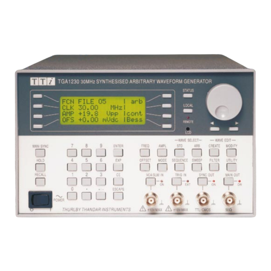
TGA1230
30 MHz Synthesised Arbitrary
Waveform Generator
User Manual
Manual Copyright © 1997 T T Instruments Ltd. All rights reserved.
Software Copyright © 1997 T T Instruments Ltd. All rights reserved.
WaveCAD Copyright © 1997 Tabor Electronics. All rights reserved.
Book Part Number 48591 - 0510 Issue 4.
Advertisement
Table of Contents

Related Manuals for TTI TGA1230

Summary of Contents for TTI TGA1230
- Page 1 TGA1230 30 MHz Synthesised Arbitrary Waveform Generator User Manual Manual Copyright © 1997 T T Instruments Ltd. All rights reserved. Software Copyright © 1997 T T Instruments Ltd. All rights reserved. WaveCAD Copyright © 1997 Tabor Electronics. All rights reserved.
-
Page 2: Table Of Contents
Contents Introduction Specifications Safety Installation Connections Front Panel Connections Rear Panel Connections General Initial Operation Principles of Operation Standard Waveform Operation Setting Generator Parameters Warnings and Error Messages SYNC Output Sweep Operation General Setting Sweep Parameters Triggered Burst and Gate General Triggered Burst Gated Mode... - Page 3 Output Filter Setting WaveCAD Arbitrary Waveform Creation Software Pulse and Pulse-trains Pulse Set-up Pulse-train Setup Waveform Hold in Pulse and Pulse-Train Modes Synchronising Generators System Operations from the Utility Menu Calibration Equipment Required Calibration Procedure Calibration Routine Remote Calibration Remote Operation Address and Baud Rate Selection Remote/Local Operation ARC Interface...
-
Page 4: Introduction
As well as operating as a conventional RS-232 interface, it can also be used in addressable mode whereby up to 32 instruments can be linked to one PC serial port as part of a TTi "ARC" system. Alternatively, a GPIB interface conforming to IEEE-488.2 is available as an option. -
Page 5: Specifications
Specifications Specifications apply at 18-28ºC after one hour warm-up, at maximum output into 50Ω WAVEFORMS Standard Waveforms Sine, square, triangle, DC, positive ramp, negative ramp, sin(x)/x, pulse, pulse train, cosine, haversine and havercosine. Sine, Cosine, Haversine, Havercosine Range: 0·1 mHz to 10 MHz. Resolution: 0·1mHz (7 digits). - Page 6 Period: Range: 133·3ns to 100s. Resolution: 4-digit. Accuracy: ±1 digit of setting. Delay: Range: -99·9s to + 99·99s Resolution: 0·002% of period or 33·33ns, whichever is greater. Width: Range: 33·3ns to 99·99s Resolution: 0·002% of period or 33·33ns, whichever is greater. Note that the pulse width and absolute value of the delay may not exceed the pulse period at any time.
- Page 7 Gated Waveform will run while the Gate signal is true and stop while false. Carrier Waveforms: All standard and arbitrary. Trigger Repetition Rate: dc to 50 kHz internal, dc to 1 MHz external. Gate Signal Source: Internal from keyboard or trigger generator. External from TRIG IN or remote interface.
- Page 8 External Signal Summing Carrier frequency: Entire range for selected waveform. Carrier waveforms: All standard and arbitrary waveforms. Sum source: VCA/SUM IN socket. Frequency Range: DC to 10MHz. Signal Range: Approximately 5Vpk-pk input for 20Vpk-pk output. Trigger Generator Internal source 0.005 Hz to 50kHz squarewave adjustable in 20us steps. 3 digit resolution. Available for external use from the SYNC OUT socket.
- Page 9 Cursor/Marker Out Adjustable output pulse for use as a marker in sweep mode or as a cursor in arbitrary waveform editing mode. Can be used to modulate the Z-axis of an oscilloscope or be displayed on a second ‘scope channel. Output Signal Level: Adjustable from nominally 2V to 14V, normal or inverted;...
- Page 10 INTERFACES Full remote control facilities are available through the RS232 (standard) or optional GPIB interfaces. RS232: Variable Baud rate, 9600 Baud maximum. 9-pin D-connector. Fully compatible with Thurlby-Thandar ARC (Addressable RS232 Chain) system. IEEE-488: Conforming with IEEE488.1 and IEEE488.2 GENERAL Display: 20 character x 4 row alphanumeric LCD.
- Page 11 Cambridgeshire PE29 7DR England declare that the TGA1230 30MHz Synthesised Arbitrary Waveform Generator with GPIB meets the intent of the EMC Directive 89/336/EEC and the Low Voltage Directive 73/23/EEC. Compliance was demonstrated by conformance to the following specifications which have been listed in the Official Journal of the European Communities.
-
Page 12: Safety
Safety This generator is a Safety Class I instrument according to IEC classification and has been designed to meet the requirements of EN61010-1 (Safety Requirements for Electrical Equipment for Measurement, Control and Laboratory Use). It is an Installation Category II instrument intended for operation from a normal single phase supply. -
Page 13: Emc
This instrument has been designed to meet the requirements of the EMC Directive 89/336/EEC. Compliance was demonstrated by meeting the test limits of the following standards: Emissions EN61326 (1998) EMC product standard for Electrical Equipment for Measurement, Control and Laboratory Use. Test limits used were: Radiated: Class B Conducted: Class B... - Page 14 for 230V operation connect the live (brown) wire to pin 15 for 115V operation connect the live (brown) wire to pin 14 for 100V operation connect the live (brown) wire to pin 13 4) Refit the cover and the secure with the same screws. 5) To comply with safety standard requirements the operating voltage marked on the rear panel must be changed to clearly show the new voltage setting.
-
Page 15: Connections
Connections Front Panel Connections MAIN OUT This is the 50Ω output from the main generator. It will provide up to 20V peak-to-peak e.m.f. which will yield 10V peak-to-peak into a matched 50Ω load. It can tolerate a short circuit for 60 seconds. -
Page 16: Rear Panel Connections
VCA/SUM IN This is the input socket for external voltage controlled amplitude (VCA) or external signal summing (SUM). The function of this input is selected from the EXT SUM/VCA SET-UP screen. For VCA operation the input impedance is nominally 6kΩ and for SUM operation it is nominally 1k2Ω. - Page 17 Pin 2, 3 and 5 may be used as a conventional RS232 interface with XON/XOFF handshaking. Pins 7,8 and 9 are additionally used when the instrument is connected to the ARC interface. Signal grounds are connected to instrument ground. The ARC address is set from the “remote” menu on the UTILITY screen, see System Operations section.
-
Page 18: General
General Initial Operation This section is a general introduction to the organisation of the instrument and is intended to be read before using the generator for the first time. Detailed operation is covered in later sections starting with Standard Waveform Operation. In this manual front panel keys and sockets are shown in capitals, e.g. - Page 19 • VCA/SUM IN, TRIG IN and SYNC OUT call screens from which the parameters of those input/outputs can be set, including whether the port is on or off; the MAIN OUT key simply switches the main output on or off. •...
-
Page 20: Principles Of Operation
In addition to their use in editing items identified by a double-headed arrow as described above, the CURSOR keys and ROTARY CONTROL operate in two other modes. In screens with lists of items that can be selected (i.e. items marked with a diamond) the cursor keys and rotary control are used to scroll all items through the display if the list has more than three items;... - Page 21 Clock Synthesis Mode In Clock Synthesis mode the addresses are always sequential (an increment of one) and the clock rate is adjusted by the user in the range 30MHz to 0·1Hz. The frequency of the waveform is clock frequency ÷ waveform length, thus allowing short waveforms to be played out at higher repetition rates than long waveforms, e.g.
-
Page 22: Standard Waveform Operation
Standard Waveform Operation This sections deals with the use of the instrument as a standard function generator, i.e. generating sine, square, triangle, dc, ramp, haversine, cosine, havercosine and sinx/x waveforms. All but squarewave are generated by DDS which gives 7-digit frequency precision; squarewave is generated by Clock Synthesis which results in only 4-digit frequency resolution. - Page 23 Squarewave, generated by Clock Synthesis has 4-digit resolution for both frequency and period entry but the hardware is still programmed in terms of frequency and the same differences may occur in switching the display from period to frequency and back to period. Turning the rotary control will increment or decrement the numeric value in steps determined by the position of the edit cursor (flashing underline);...
- Page 24 Turning the rotary control will increment or decrement the numeric value in steps determined by the position of the edit cursor (flashing underline); the cursor is moved by the left and right arrowed cursor keys. Because DC offset can have negative values, the rotary control can take the value below zero;...
-
Page 25: Warnings And Error Messages
Warnings and Error Messages Two classes of message are displayed on the screen when an illegal combination of parameters is attempted. WARNING messages are shown when the entered setting causes some change which the user might not necessarily expect. Examples are: Changing the amplitude from, for example, 2·5 Volts pk-pk to 250mV pk-pk brings in the step attenuator;... -
Page 26: Sync Output
SYNC Output SYNC OUT is a multifunction CMOS/TTL level output that can be automatically or manually set to be any of the following: • Waveform Sync : A square wave with 50% duty cycle at the main waveform frequency, or a pulse coincident with the first few points of an arbitrary waveform. -
Page 27: Sweep Operation
Sweep Operation General Principles of Sweep Operation All standard and arbitrary waveforms can be swept with the exception of pulse, pulse-train and sequence. During Sweep all waveforms are generated in DDS mode because this offers the significant advantage of phase-continuous sweeps over a very wide frequency range (up to 10 However, it must be remembered that the frequency is actually stepped, not truly linearly swept, and thought needs to be given as to what the instrument is actually doing when using extreme combinations of sweep range and time. -
Page 28: Setting Sweep Parameters
Setting Sweep Parameters Pressing the SWEEP key (or the sweep setup soft-key on the MODE screen) displays the SWEEP SETUP screen. SWEEP SETUP: ◊range… type… ◊ ◊time… spacing… ◊ ◊manual… marker… ◊ Menus for setting up the range, time (sweep rate), type (continuous, triggered, etc.) spacing (lin/log) and marker position are all accessed from this screen using the appropriate soft-key. - Page 29 Sweep Type Pressing the type soft-key calls the SWEEP TYPE screen. SWEEP TYPE: continuous ◊direction: up ◊sync: on done ◊ This screen is used to set the sweep mode (continuous; triggered; triggered, hold and reset; manual) and sweep direction. Alternate presses of the direction soft-key change the sweep direction from up, i.e. start frequency to stop frequency, to down, i.e.
- Page 30 Before manual control can be used, manual must be selected on the SWEEP TYPE screen, see above; if manual has not been set, the message mode is not manual will be displayed instead of the frequency. In manual mode the frequency can be stepped through the sweep range, defined on the SWEEP RANGE screen, using the rotary control or cursor keys.
-
Page 31: Triggered Burst And Gate
Triggered Burst and Gate General Triggered Burst and Gated modes are selected from the MODE screen, called by the MODE key, as alternatives to the default continuous mode. MODE: continuous ◊gated ◊triggered setup…◊ In Triggered Burst mode a defined number of cycles are generated following each trigger event. This mode is edge triggered. -
Page 32: Triggered Burst
Triggered Burst Triggered Burst mode is turned on with the triggered soft-key on the MODE screen. The setup… soft-key on this screen accesses the TRIGGER SETUP screen on which the burst count is set. The other trigger parameters are set on the TRIGGER INPUT SETUP screen called by pressing the TRIG IN key. -
Page 33: Gated Mode
Gated Mode Gated mode is turned on with the gated soft-key on the MODE screen. The parameters associated with Gated are set on the TRIGGER INPUT SETUP screen called by pressing the TRIG IN key. TRIGGER INPUT SETUP: ◊source: internal ◊slope: positive period: 2·00ms Gate Source... -
Page 34: Tone Mode
Tone Mode General In Tone mode the generator output is stepped through a user-defined list of up to 16 frequencies under the control of a signal applied to the TRIG IN socket. A true level at TRIG IN will output the tone;... - Page 35 When tone mode is switched on the source for TRIG IN is automatically switched to external on the TRIGGER INPUT SETUP screen and cannot be changed. The slope, however, can be set to either positive or negative; positive means that a high level at TRIG IN will be treated as true and negative means that a low level will be true;...
-
Page 36: Other Modulation Modes
Other Modulation Modes External VCA When used in VCA (Voltage Controlled Amplitude) mode the MAIN OUT amplitude is directly proportional to the external modulating signal voltage applied to the VCA/SUM IN socket. Suppressed carrier modulation (SCM) is achievable in this mode. To use VCA mode set VCA/SUM input: to VCA on the EXT VCA/SUM SETUP screen which is called by pressing the VCA/SUM IN key: EXT VCA/SUM SETUP... -
Page 37: Amplitude Range For Each Attenuator Step
of the instrument is achieved by switching in up to five -10dB attenuation stages. For generator amplitudes in the range ~6·3Vpp to 20Vpp (20Vpp -10dB ≈6·3V) a corresponding signal range at SUM IN to force the generator output to 20Vpp would be ~5Vpp to 0V. If, however, the generator amplitude is in the range 630mV to 2·0Vpp (i.e. -
Page 38: Arbitrary Waveform Generation
Arbitrary Waveform Generation Introduction Arbitrary (Arb) waveforms are generated by sequentially addressing the RAM containing the waveform data with the arbitrary clock. The frequency of the arb waveform is determined both by the arb clock and the total number of data points in the cycle. In this instrument an arb waveform can have up to 65536 horizontal points. -
Page 39: Creating New Waveforms
Creating New Waveforms Pressing the CREATE key calls the CREATE NEW WAVEFORM screen. CREATE NEW WAVEFORM free memory: 65536 ◊create blank… ◊create from copy… Create Blank Waveform Pressing the create blank… soft-key calls the menu: create: “wv01 ” ◊size: 01024 ◊cancel create ◊... -
Page 40: Modifying Arbitrary Waveforms
Modifying Arbitrary Waveforms Pressing the MODIFY front panel key, or the create soft-key on either of the CREATE NEW WAVEFORM menus calls the MODIFY screen. MODIFY: wv01 ◊ resize… rename…◊ ◊delete… limits…◊ ◊edit waveform… This screen gives access to a number of menus which permit the selected waveform to be resized, renamed, edited, etc. - Page 41 Return to the MODIFY screen by pressing rename (which implements the new name) or cancel. Delete Waveform Pressing the delete… soft-key displays a request for confirmation that the selected waveform is to be deleted. Delete waveform “wv01 ” ◊cancel delete ◊ Confirm deletion by pressing the delete soft-key which will return the display to the MODIFY screen with the next arb waveform automatically selected;...
- Page 42 Point Edit Press the point edit… soft-key to call the POINT EDIT screen: POINT EDIT (addrs, value) ◊ (00512, +0500) ◊exit next point◊ To modify a point, press the addrs soft-key and enter the address directly from the keyboard or by using the rotary control;...
- Page 43 The insert is actioned by pressing the insert soft-key. If there is a size difference between the two sections of waveform then the software will expand or compress the source to fit the new waveform. Compressing the waveform may lose some significant data. To insert sections of the current waveform within itself see Block Copy.
- Page 44 Waveform Offset Pressing the wave offset soft-key calls the WAVE OFFSET screen. WAVE OFFSET: +0000 ◊start: 00400 ◊stop: undo ◊ 01000 ◊exit save ◊ The waveform offset can be changed on a section of the waveform defined by the start and stop addresses.
-
Page 45: Arbitrary Waveform Sequence
changed at each new address with the right-hand soft-key. Markers show immediately they are changed. Alternatively, markers can be input as patterns by using the patterns… sub-menu. PATTERN: 00000000… ◊start: 00000 ◊stop: 01023 ◊exit: do pattern ◊ The start and stop addresses of the markers within the waveform are set using the start and stop soft-keys respectively followed by a direct keyboard entry or by rotary control. -
Page 46: Frequency And Amplitude Control With Arbitrary Waveforms
Once the segment to be edited has been set the waveform for that segment is selected with the wfm (waveform) soft-key; the list of all arbitrary waveforms already created is stepped through with repeated presses of the wfm soft-key or by using the rotary control. The part of the waveform that will be used is defined by the limits setting (default setting is the whole waveform) as described in the Waveform Limits paragraph of the Modifying Arbitrary Waveforms section. -
Page 47: Sync Out Settings With Arbitrary Waveforms
ARBITRARY FREQUENCY 30·00 waveform ◊ sample period ◊ freq Frequency can be set in terms of frequency or period as before by pressing the freq or period soft-key respectively. Note that the frequency and period resolution in arbitrary mode is only 4 digits because Clock Synthesis generation is used, see Principles of Operation section. -
Page 48: Waveform Hold In Arbitrary Mode
the position marker pattern where markers go from off to on) with respect to the arbitrary waveform from the main output, for example. Waveform Hold in Arbitrary Mode There are a number of ways in which arb waveforms can be held and restarted. Pressing the front panel HOLD key stops the waveform at the current level;... -
Page 49: Wavecad Arbitrary Waveform Creation Software
WaveCAD Arbitrary Waveform Creation Software WaveCAD is a powerful Windows-based design tool that enables the user to create waveforms from mathematical expressions, from combinations of other waveforms, “freehand”, or using a combination of all three techniques. WaveCAD creates waveforms that are up to 65536 points long with a vertical resolution of 12- bits. - Page 50 Example 2 : 10 Sinewaves Ampl (p) = amp∗sin(omg∗p∗10) Multiplying the variable ‘p’ by 10 means that for every step in p the sinewave argument increases by 10 x p; the result is 10 complete sinewaves in the period defined by the start and end points.
-
Page 51: Pulse And Pulse-Trains
Pulse and Pulse-trains Pulse and pulse-trains are both selected and set-up from independent menus on the STANDARD WAVEFORMS screen called by pressing the STD key. Pulse and pulse-trains have similar timing set-ups and considerations but pulses are only unipolar, with a maximum amplitude of 10Vpp, whereas pulse-trains can be bipolar, with a maximum peak-to-peak of 20Vpp. -
Page 52: Pulse-Train Setup
For periods above 1·67ms the maximum number of points in the waveform (50,000) becomes the factor determining pulse width and delay resolution. For example, with the period set to 100ms, the smallest pulse width and delay increment is 2µs (100ms÷50,000). This may appear to cause significant “errors”... - Page 53 Pressing next calls the pulse train period screen: Enter pulse train period: 100·0us ◊done next◊ The period can be set, with 4-digit resolution, from 133·3ns to 100s by direct keyboard entries or by using the rotary control. Pressing next calls the baseline voltage screen, the last of the general setup screens: Enter the baseline voltage: +0·000 V...
-
Page 54: Waveform Hold In Pulse And Pulse-Train Modes
for exactly the same reasons as described in the Pulse Setup section; refer to that section for a detailed explanation. Pressing next calls the pulse delay screen for the first pulse: ◊Pulse 1 delay program +0·000 ns (actual +0·000 ns) ◊done next◊... -
Page 55: Synchronising Generators
Synchronising Generators Two or more generators can be synchronised together following the procedure outlined below; the number of generators that can be linked in this way will depend on the clocking arrangement, cable lengths, etc., but problems should not be experienced with up to 4 generators. Synchronising Principles Frequency locking is achieved by using the clock output from the ‘master’... - Page 56 REF. CLOCK I/O SETUP ◊input ◊output phase…◊ phase lock slave Repeated presses of the phase lock soft-key toggle between master and slave. The slaves are set to slave and the phase relationships between the slaves and the master are set individually on the SLAVE PHASE ANGLE screens of each slave, accessed by pressing the phase…...
-
Page 57: System Operations From The Utility Menu
System Operations from the Utility Menu Pressing the UTILITY key calls a list of menus which give access to various system operations including storing/recalling setups from non-volatile memory, error messages, power on settings and calibration. Storing and Recalling Setups Complete waveform setups can be stored to or recalled from non-volatile RAM using the menus called by the store and recall soft-keys. - Page 58 reference when an adequate signal level (TTL/CMOS threshold) is detected at REF CLOCK IN/OUT but will continue to run from the internal clock in the absence of such a signal. With the clock set to output a buffered version of the internal 10MHz clock is made available at the socket.
- Page 59 The setting loaded can be selected with the appropriate soft-key to be default values (the default setting), restore last setup (i.e. the settings at power down are restored at power up) or any of the settings stored in non-volatile memories 1 to 9. Default values restores the factory default settings, see Appendix 3.
-
Page 60: Calibration
Calibration All parameters can be calibrated without opening the case, i.e. the generator offers ‘closed-box’ calibration. All adjustments are made digitally with calibration constants stored in EEPROM. The calibration routine requires only a DVM and a frequency counter and takes no more than a few minutes. -
Page 61: Calibration Routine
ENTER PASSWORD ---- When the correct password has been entered from the keyboard the display changes to the opening screen of the calibration routine and calibration can proceed as described in the Calibration Routine section. If an incorrect password is entered the message INCORRECT PASSWORD! is shown for two seconds before the display reverts to the UTILITY menu. -
Page 62: Remote Calibration
CAL 17 40dB attenuator Adjust for 0·1V ± ·1mV. CAL 18 10dB attenuator Adjust for 2·236V AC ± 10mV. CAL 19 Clock calibrate Adjust for 10·00000 MHz at SYNC OUT. Remote Calibration Calibration of the instrument may be performed over the RS232 or GPIB interface. To completely automate the process the multimeter and frequency meter will also need to be remote controlled and the controller will need to run a calibration program unique to this instrument. -
Page 63: Remote Operation
Remote Operation The following sections detail the operation of the instrument via both GPIB and ARC. Where operation is identical no distinction is made between the two. Where differences occur these are detailed in the appropriate sections or in some cases separate sections for GPIB and ARC. It is therefore only necessary to read the general sections and those sections specific to the interface of interest. -
Page 64: Arc Interface
ARC Interface ARC Interface Connections The 9-way D-type serial interface connector is located on the instrument rear panel. The pin connections are as shown below: Name Description No internal Connection Transmitted data from instrument Received data to instrument No internal connection Signal ground No internal connection RXD2... - Page 65 The ARC standard for the other interface parameters is as follows: Start bits Data bits Parity None Stop bits In this instrument, as with most other ARC instruments, these parameters are fixed. ARC Character Set Because of the need for XON/XOFF handshake it is possible to send ASCII coded data only; binary blocks are not allowed.
-
Page 66: Gpib Interface
UDC Universal Device Clear. Before a response can be read from an instrument it must be addressed to talk by sending the Talk Address control code, 14H (TAD) followed by a single character which has the lower 5 bits corresponding to the unique address of the required instrument, as for the listen address control code above. - Page 67 GPIB Subsets This instrument contains the following IEEE 488.1 subsets: Source Handshake Acceptor Handshake AH1 Talker Listener Service Request Remote Local Parallel Poll Device Clear Device Trigger Controller Electrical Interface GPIB IEEE Std. 488.2 Error Handling The IEEE 488.2 error (addressed to talk with nothing to say) is handled as follows. UNTERMINATED If the instrument is addressed to talk and the response formatter is inactive and the input queue is empty then the...
-
Page 68: Power On Settings
bit 6 bit 5 Parallel poll enable bit 4 bit 3 Sense sense of the response bit; 0 = low, 1 = high bit 2 bit 1 bit position of the response bit 0 Example. To return the RQS bit (bit 6 of the Status Byte Register) as a 1 when true and a 0 when false in bit position 1 in response to a parallel poll operation send the following commands ∗PRE 64... - Page 69 Standard Event Status and Standard Event Status Enable Registers These two registers are implemented as required by the IEEE std. 488.2. Any bits set in the Standard Event Status Register which correspond to bits set in the Standard Event Status Enable Register will cause the ESB bit to be set in the Status Byte Register. The Standard Event Status Register is read and cleared by the ∗ESR? command.
- Page 70 Bit 7 - Not used. Bit 6 - RQS/MSS. This bit, as defined by IEEE Std. 488.2, contains both the Requesting Service message and the Master Status Summary message. RQS is returned in response to a Serial Poll and MSS is returned in response to the ∗STB? command. Bit 5 - ESB.
-
Page 71: Arc Remote Command Formats
ARC Remote Command Formats Serial input to the instrument is buffered in a 256 byte input queue which is filled, under interrupt, in a manner transparent to all other instrument operations. The instrument will send XOFF when approximately 200 characters are in the queue. XON will be sent when approximately 100 free spaces become available in the queue after XOFF was sent. - Page 72 is any of the commands in the REMOTE COMMANDS section. <PROGRAM MESSAGE UNIT> Responses from the instrument to the controller are sent as <RESPONSE MESSAGES> consists of one followed by a <RESPONSE MESSAGE> <RESPONSE MESSAGE UNIT> <RESPONSE MESSAGE TERMINATOR> is the new line character with the END message NL^END. <RESPONSE MESSAGE TERMINATOR>...
-
Page 73: Remote Commands
Remote Commands The following section lists all commands and queries implemented in this instrument. For simplicity, commands are grouped by function. The REMOTE COMMAND SUMMARY lists the commands in alphabetical order, for reference. Note that there are no dependent parameters, coupled parameters, overlapping commands, expression program data elements or compound command program headers and that each command is completely executed before the next command is started. -
Page 74: Waveform Selection And Definition
Waveform Selection and Definition WAVE <cpd> Select the output waveform as <SINE>, <SQUARE>, <TRIANG>, <DC>, <POSRMP>, <NEGRMP>, <COSINE>, <HAVSIN>, <HAVCOS>, <SINC>, <PULSE>, <PULSTRN>, <ARB> or <SEQ>. PULSPER <nrf> Set the pulse period to <nrf> sec. PULSWID <nrf> Set the pulse width to <nrf> sec. PULSDLY <nrf>... -
Page 75: Waveform Sequence Control
ARBDATA? <cpd> Returns the data from an existing arbitrary waveform. <cpd> must be the name of an existing arbitrary waveform. The data consists of binary coded values as specified for the ARBDATA command. The data is sent from the arbitrary waveform between the points specified by the ARBLIMITS command. -
Page 76: Arbitrary Waveform Editing
Arbitrary Waveform Editing ARBLIMITS Set the limits for the arbitrary waveform with name <cpd> to start at <cpd>,<nrf1>,<nrf2> <nrf1> and stop at <nrf2>. ARBRESIZE <cpd>,<nrf> Change the size of arbitrary waveform <cpd> to <nrf>. ARBRENAME <cpd1>,<cpd2> Change the name of arbitrary waveform <cpd1> to <cpd2>. ARBDELETE <cpd>... -
Page 77: Mode Commands
Mode Commands MODE <cpd> Set the mode to <CONT>, <GATE>, <TRIG>, <SWEEP> or TONE. BSTCNT <nrf> Set the burst count to <nrf>. BSTCLK <cpd> Set the burst counter clock to <POSNMKR> or <WFMSYNC>. TONEFREQ <nrf1>,<nrf2> Set tone frequency number <nrf1> to <nrf2> Hz. TONEEND <nrf>... -
Page 78: Status Commands
Status Commands ∗ Clear status. Clears the Standard Event Status Register, Query Error Register and Execution Error Register. This indirectly clears the Status Byte Register. ∗ Set the Standard Event Status Enable Register to the value of <nrf>. ESE <nrf> ∗... -
Page 79: Miscellaneous Commands
Miscellaneous Commands ∗ Returns the complete set up of the instrument as a hexadecimal character LRN? data block approximately 842 bytes long. To re-install the set up the block should be returned to the instrument exactly as it is received. The syntax of the response is LRN <Character data><rmt>. -
Page 80: Remote Command Summary
Remote Command Summary ∗ Clear status. ∗ Set the Standard Event Status Enable Register to the value of <nrf>. ESE <nrf> ∗ Returns the value in the Standard Event Status Enable Register in <nr1> ESE? numeric format. ∗ Returns the value in the Standard Event Status Register in <nr1> ESR? numeric format. - Page 81 ARBDATA <cpd>, Load data to an existing arbitrary waveform. <bin data block> ARBDATA? <cpd> Returns the data from an existing arbitrary waveform. ARBDATACSV Load data to an existing arbitrary waveform. <cpd>,<csv ascii data> ARBDATACSV? <cpd> Returns the data from an existing arbitrary waveform. ARBDEF <cpd>,<nrf>, Define a new or existing arbitrary waveform with name <cpd>...
- Page 82 LOCAL Returns the instrument to local operation and unlocks the keyboard. Will not function if LLO is in force. ∗ LRN <character data> Install data for a previous LRN? command. MODE <cpd> Set the mode to <CONT>, <GATE>, <TRIG>, <SWEEP> or TONE. OUTPUT <cpd>...
-
Page 83: Maintenance
SWPSYNC <cpd> Set the sweep sync <ON> or <OFF>. SWPTIME <nrf> Set the sweep time to <nrf> sec. SWPTYPE <cpd> Set ten sweep type to <CONT>, <TRIG>, <THLDRST> or <MANUAL>. SYNCOUT <cpd> Set the sync output <ON>, <OFF>, <AUTO>, <WFMSYNC>, <POSNMKR>, <BSTDONE>, <SEQSYNC>, <TRIGGER>, <SWPTRG>... -
Page 84: Appendix 1. Warning And Error Messages
Appendix 1. Warning and Error Messages Warning messages are given when a setting may not give the expected result, e.g. DC Offset attenuated by the output attenuator when a small amplitude is set; the setting is, however, implemented. Error messages are given when an illegal setting is attempted; the previous setting is retained. The last two warning/error messages can be reviewed by selecting LAST ERROR from the UTILITY screen, the latest is reported first. - Page 85 Arb waveform length exceeds available memory Arb waveform length cannot be less than four points Waveform limit value out of range Start address error: must be in the range 0 <= n <= stop addr Stop address error: must be in the range strt <= n <= wfm len No GPIB interface is available System ram error check battery Point value error: must be in the range -2048 <= n <= +2047...
- Page 86 Remote Errors Illegal store number requested Byte value outside the range 0 to 255 Specified arb name does not exist Command illegal in sweep or tone mode Cannot set waveform frequency or period for a sequence Cannot set sample frequency or period for std waveforms dBm output units assume a 50 Ohm termination Specified units illegal for the selected waveform Command not available for RS232...
-
Page 87: Appendix 2. Sync Out Automatic Settings
Appendix 2. SYNC OUT Automatic Settings The following automatic source (src) settings are made when auto mode is selected on the SYNC OUTPUT SETUP screen. Waveform Position Burst Sequence Sweep Phase MODE WAVEFORM Sync Marker Done Sync Trigger Trigger Lock Standard Continuous Arbitrary... -
Page 88: Appendix 3. Factory System Defaults
Appendix 3. Factory System Defaults The factory system defaults are listed in full below. They can be recalled by pressing RECALL followed by set defaults or by the remote command ∗RST. Main Parameters Std. Wave: Sine Frequency: 10kHz Output: +2·0Vpp ;...
Need help?
Do you have a question about the TGA1230 and is the answer not in the manual?
Questions and answers