Table of Contents
Advertisement
Quick Links
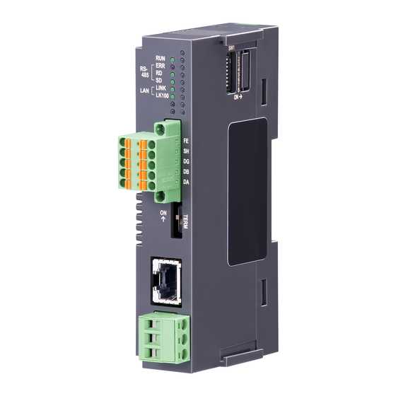
INSTRUCTION MANUAL
ETHERNET/RS-485 ADAPTOR
BEFORE USE ....
Thank you for choosing M-System. Before use, please check
contents of the package you received as outlined below.
If you have any problems or questions with the product,
please contact M-System's Sales Office or representatives.
■ PACKAGE INCLUDES:
Ethernet/RS-485 adaptor ....................................................(1)
■ MODEL NO.
Confirm Model No. marking on the product to be exactly
what you ordered.
■ INSTRUCTION MANUAL
This manual describes necessary points of caution when
you use this product, including installation, connection and
basic maintenance procedures.
(Modbus use)
5-2-55, Minamitsumori, Nishinari-ku, Osaka 557-0063 JAPAN
Phone: +81(6)6659-8201 Fax: +81(6)6659-8510 E-mail: info@m-system.co.jp
MODEL
POINTS OF CAUTION
■ CONFORMITY WITH EU DIRECTIVES
• The equipment must be mounted inside a panel.
• The actual installation environments such as panel con-
figurations, connected devices, connected wires, may af-
fect the protection level of this unit when it is integrated
in a panel system. The user may have to review the CE
requirements in regard to the whole system and employ
additional protective measures to ensure the CE conform-
ity.
■ POWER INPUT RATING & OPERATIONAL RANGE
• Locate the power input rating marked on the product and
confirm its operational range as indicated below:
24V DC rating: 24V ±10%, ≤ 1.5W
■ GENERAL PRECAUTIONS
• Before you remove the unit or mount it, turn off the power
supply for safety.
■ ENVIRONMENT
• Indoor use.
• When heavy dust or metal particles are present in the
air, install the unit inside proper housing with sufficient
ventilation.
• Do not install the unit where it is subjected to continuous
vibration. Do not subject the unit to physical impact.
• Environmental temperature must be within -10 to +55°C
(14 to 131°F) with relative humidity within 10 to 90% RH
in order to ensure adequate life span and operation.
■ WIRING
• Do not install cables close to noise sources (relay drive
cable, high frequency line, etc.).
• Do not bind these cables together with those in which
noises are present. Do not install them in the same duct.
■ AND ....
• The unit is designed to function as soon as power is sup-
plied, however, a warm up for 10 minutes is required for
satisfying complete performance described in the data
sheet.
GR8-EM
EM-8621 Rev.5 P. 1 / 15
Advertisement
Table of Contents

Summary of Contents for M-system GR8-EM
-
Page 1: Before Use
(Modbus use) BEFORE USE ..POINTS OF CAUTION Thank you for choosing M-System. Before use, please check ■ CONFORMITY WITH EU DIRECTIVES contents of the package you received as outlined below. • The equipment must be mounted inside a panel. -
Page 2: Component Identification
Note: Be sure to set unused SW1-3 through 1-8 to OFF. ■ TERMINATING RESISTOR SETTING SW • Terminating resistor TERM INCORPORATED TERMINATING RESISTOR Disabled ON (*) Enabled EM-8621 Rev.5 P. 2 / 15 5-2-55, Minamitsumori, Nishinari-ku, Osaka 557-0063 JAPAN Phone: +81(6)6659-8201 Fax: +81(6)6659-8510 E-mail: info@m-system.co.jp... -
Page 3: Wiring Instructions
Recommended pin terminals: AI0,25-10YE 0.25 mm (Phoenix Contact) AI0,34-10TQ 0.34 mm (Phoenix Contact) AI0,5-10WH 0.5 mm (Phoenix Contact) AI0,75-10GY 0.75 mm (Phoenix Contact) EM-8621 Rev.5 P. 3 / 15 5-2-55, Minamitsumori, Nishinari-ku, Osaka 557-0063 JAPAN Phone: +81(6)6659-8201 Fax: +81(6)6659-8510 E-mail: info@m-system.co.jp... -
Page 4: Installation
Align the hooks on the cover with the grooves of the unit and slide the cover straight until the hooks are latched. groove hook When removing the cover by DIP SW setting, pull it out while squeezing the hooks inward. EM-8621 Rev.5 P. 4 / 15 5-2-55, Minamitsumori, Nishinari-ku, Osaka 557-0063 JAPAN Phone: +81(6)6659-8201 Fax: +81(6)6659-8510 E-mail: info@m-system.co.jp... -
Page 5: Single Use
Note: When the unit is mounted on a DIN rail attached on the wall surface in vertical direction, use of an attachment plate to prevent the module from sliding down is recommended. EM-8621 Rev.5 P. 5 / 15 5-2-55, Minamitsumori, Nishinari-ku, Osaka 557-0063 JAPAN Phone: +81(6)6659-8201 Fax: +81(6)6659-8510 E-mail: info@m-system.co.jp... -
Page 6: Terminal Connection
RS-485 devices MODBUS WIRING CONNECTION GR8-EM RS-485 devices Terminating Resistor * Turn the terminating resistor SW “ON” to use the incorporated terminating resistor. EM-8621 Rev.5 P. 6 / 15 5-2-55, Minamitsumori, Nishinari-ku, Osaka 557-0063 JAPAN Phone: +81(6)6659-8201 Fax: +81(6)6659-8510 E-mail: info@m-system.co.jp... - Page 7 Fetch Comm. Event Counter (11) Fetch Comm. Event Log (12) Force Multiple Coils (15) Preset Multiple Registers (16) Report Slave ID (17) EM-8621 Rev.5 P. 7 / 15 5-2-55, Minamitsumori, Nishinari-ku, Osaka 557-0063 JAPAN Phone: +81(6)6659-8201 Fax: +81(6)6659-8510 E-mail: info@m-system.co.jp...
-
Page 8: Cache Function
The GR8-EM regularly communicates with the client (RS-485) I/O modules regardless of the presence or absence of requests from the host (Ethernet) and stores data in its Cache area. Whenever a query is received from the host, the GR8-EM sends data stored in the Cache without loss of time to scan the client each time. -
Page 9: System Configuration Example
GR8-EM SYSTEM CONFIGURATION EXAMPLE Devices other than the GR8-EM in below provided by the user. ■ COUPLED WITH DL8 DL8 Client I/O modules GR8-EM RS-485 24V DC power Remote I/O modules Note: It is not available to supply the power via DL8. -
Page 10: Configuration With Web Browser
The GR8-EM is capable of Web server. A PC, tablet or smart phone can configure the GR8-EM via Ethernet. Note: As the GR8-EM employs only Ethernet I/F, A PC, tablet or smart phone, which has only wireless LAN I/F, cannot be connected directly. - Page 11 Password Set the password for login to setting menu. Max. 64 characters are available. * *1. ”, # and \ are excluded. EM-8621 Rev.5 P. 11 / 15 5-2-55, Minamitsumori, Nishinari-ku, Osaka 557-0063 JAPAN Phone: +81(6)6659-8201 Fax: +81(6)6659-8510 E-mail: info@m-system.co.jp...
- Page 12 Set the time to cut off the connection when there are no transmission or receiving within certain time from connection established. Range : 1 to 60 minutes EM-8621 Rev.5 P. 12 / 15 5-2-55, Minamitsumori, Nishinari-ku, Osaka 557-0063 JAPAN Phone: +81(6)6659-8201 Fax: +81(6)6659-8510 E-mail: info@m-system.co.jp...
- Page 13 Inter-frame Interval (ms) Set the delay time from when response receiving till when transmitting next transmit frame (msec.). Range : 0 to 500 milli-seconds EM-8621 Rev.5 P. 13 / 15 5-2-55, Minamitsumori, Nishinari-ku, Osaka 557-0063 JAPAN Phone: +81(6)6659-8201 Fax: +81(6)6659-8510 E-mail: info@m-system.co.jp...
- Page 14 Error receive frames The numbers that response is error frame Timeout receive frames The numbers of time out that there are no response EM-8621 Rev.5 P. 14 / 15 5-2-55, Minamitsumori, Nishinari-ku, Osaka 557-0063 JAPAN Phone: +81(6)6659-8201 Fax: +81(6)6659-8510 E-mail: info@m-system.co.jp...
- Page 15 Firmware update is available in order to add new functions and improve operations. Download the firmware from M-System web site. After browsing the file, clicking “Up- date” button enables to start the firmware update. Do not turn off the power while the firmware update is proceeding.