
Related Manuals for Pavone Systems MC 353

Summary of Contents for Pavone Systems MC 353
- Page 1 Pavone Sistemi pesatura elettronica industriale TECHNICAL MANUAL MC 353 Flow Rate Controller for belt weigher Software version 1.9 Rev. 201301...
-
Page 2: Symbols
SYMBOLS Following are the symbols used throughout the manual to call reader’s attention: Warning! Electric shock risk Warning! This operation shall be carried out by qualified staff. Pay special attention to the following points. Further details. WARNINGS This manual provides texts and pictures to inform the operator about all prescriptions and criteria ne- cessary for installing and using this instrument. -
Page 3: Table Of Contents
Table of conTenTs SYMBOLS ..................... 2 WARNINGS ....................2 CE DECLARAtION Of CONfORMItY - ............5 1 - INtRODUCtION ..................6 1.1 - OtHER fUNCtIONS Of MC353 ............. 8 1.2 - tECHNICAL fEAtURES ................9 2 - MC353 INStALLAtION ................12 2.1 - INStALLAtION WARNINGS AND INDICAtIONS ........ - Page 4 6.2 - fILE LOADING ..................54 6.3 - RECEIPt PRINt ..................55 7 - SERIAL COMMUNICAtION AND PROtOCOLS .......... 56 7.1 - ASCII COMMUNICAtION PROtOCOL ..........56 7.2 - MODBUS COMMUNICAtION PROtOCOL ..........61 7.3 - PROfIBUS-DP COMMUNICAtION PROtOCOL ........62 7.4 - SUPERVISION fUNCtIONS ..............
-
Page 5: Ce Declaration Of Conformity
- CE DECLARATION OF CONFORMITY - ELECTROMAGNETIC COMPATIBILITY DIRECTIVE 2004/108/EC EN61000-6-2, EN61000-6-3, EN61010-1, EN45501 STANDARDS MANUfACtURER Pavone Sistemi S.r.l. Via Dei Chiosi, 18 20873 Cavenago Brianza (MB) - ITALY Tel. +39.02.95339165 - Fax +39.02.9501252 pavone@pavonesistemi.it - www.pavonesistemi.it ELECtRONIC IDENtIfICAtION Electronic commercial denomination: “Metering control electronic instrument”... -
Page 6: Introduction
Optional USB HOST port with USB pen drive interface. FLOW RATE CONTROLLER The MC 353 control unit is configured with P.I. (instantaneous flow rate) regulator; it processes the weight and speed variables to get the instantaneous hourly flow rate and the totalized weight. Furthermore it acts as flow rate self-regulator. - Page 7 The external supervisor transmits the work set-up (that can be set also through the keyboard) through the serial communication to the MC353 control unit; the latter, according to the calculated flow rate value, controls directly (through analogue output) the inverter frequency of the motor where the weighing system has been installed.
-
Page 8: Other Functions Of Mc353
1.1 - OTHER FUNCTIONS OF MC353 MASTER-SLAVE OPERATION This instrument can operate as slave, thus acquiring the flow rate setpoint in continuous duty, through analogue input (0÷10V / 4÷20mA) or digital input (RS485). The flow rate setpoint is updated accor- ding to the current input: the flow rate setpoint is divided and it represents the input scale end (100%). -
Page 9: Technical Features
1.2 - TECHNICAL FEATURES STRUCTURAL FEATURES front panel Made of aluminium with polycarbonate screen Protection class: IP 65 Overall dimensions: 196 mm x 105 mm (l x h) Panel front projection: 5 mm Assembly Built-in panel front. Drilling template 187 mm x 97 mm (l x h) fixing by means of 4 metallic threaded rods 3 mm rubber seal along all perimeter Rear panel... - Page 10 LOAD CELLS INPUT No. of channels 2 input channels for load cells. Acquisition at intervals or simultaneously at low frequency 5 Vdc / 120mA (max. 8 350 Ohm cells in parallel) Cells supply Protected against short circuit Input sensitivity 0.02 microV min <...
- Page 11 LOGIC I/O No. of channels 6 opto-isolated logic outputs (clean contact) 6 opto-isolated logic inputs (PNP) Output power 30 Vdc max / 60 mA each Input voltage 12 ÷ 24Vdc (external supply) Additional I/O Up to 4 external modules with 4 in. / 8 out. each (16 in.
-
Page 12: Mc353 Installation
Vdc relays, etc.) INSTRUMENT IDENTIFICATION PLATE Pavone Sistemi s.r.l. mod. MC 353 s.n. 2010/0000 In case of information or indications request concerning the instrument it is important to report such data along with the programme number and version that are printed on the manual cover and displayed upon instrument switching-on. -
Page 13: Instructions For A Correct Installation
2.2 - INSTRUCTIONS FOR A CORRECT INSTALLATION OF THE LOAD CELLS AND THE MICROPROCESSOR SYSTEMS 1. Do not carry out weldings with load cells fitted. 2. Use a copper conductor to connect the load upper support plate with the lower one, then connect both upper plates with the earth line. -
Page 14: Electric Connections
2.3 - ELECTRIC CONNECTIONS Only qualified personnel shall carry out the procedures described below. All connections shall be made with instrument OFF. TERMINAL BLOCKS DIAGRAM LOAD CELL CONNECTION (CONTACTS 1÷6 LOwER TERMINAL BLOCk) - The cell cable shall not be inserted together with other cables (for eg. outputs connected with remote control switches or supply cables), it must be routed in its own path. - Page 15 6 WIRES CELL CONNECtION Lower terminal block SIGNAL - NUM. (pitch 5.08 mm) POWER SUPPLY + REfERENCE + Cell supply - SIGNAL + Cell supply + REfERENCE - POWER SUPPLY Reference cell + 4 WIRES CELL CONNECtION Reference cell - SIGNAL - POWER SUPPLY + Signal cell -...
- Page 16 IN1 - Run static input. Close this contact to enable instrument begin and maintain programmed operations (weighing, flow regulation, alarms etc.). Input must be kept closed during dosing; open the contact to stop operations. IN2 - Manual selection (open) / automatic (closed). The selection through the keyboard has the priority over the selection of this input.
- Page 17 OUT1 - Total Set reached. This output is active when the total conveyed product exceeds the set value, anticipated of the set flying material. If the set value is zero, this output is never excited. The output is disabled when the total conveyed product is reset. OUT2 - Total PreSet reached.
- Page 18 INSTRUMENT POwER SUPPLY (CONTACTS 23-24, LOwER TERMINAL BLOCk) The instrument is supplied by the 2-pole terminal block with 7.5 mm pitch. The supply cable shall be inserted separately from other supply cables featuring a different voltage, from the load cell, encoder and logic and analogue input/output cables. Lower terminal block NUM.
- Page 19 COM3 - RS232 SERIAL PORT (CONTACTS 3÷6, UPPER TERMINAL BLOCk) This communication port is only provided with data transmission functions with fixed communication parameters. The units that can be connected are a repetition printer or display that shall feature an RS232 serial interface.
- Page 20 COM1 - RS422/485 SERIAL PORT (CONTACTS 8÷11, UPPER TERMINAL BLOCk) Through the RS422/RS485 serial interface it is possible to carry out serial connections for long distances. This type of connection allows also to connect more instruments to one MASTER unit (personal computer, PLC, etc.), using only one serial line and thus just one MASTER serial port.
- Page 21 In case of connections with double pairs RS422 and more nodes, same 120 Ohm value is indicated at the figure, but this is valid for very long lines (hundreds of meter). If line is consi- derably shorter, resistance value must raise because impendence at 120 Ohm would be very low, 60 Ohm (not counting the receivers...
- Page 22 Printer from panel RS232 COM 3 Repetitor display MAIN ANALOGUE OUTPUT (CONTACTS 12÷14, UPPER TERMINAL BLOCk) The instrument is provided with a current and a voltage analogue output. Features: - Voltage analogue output: range from 0 to 10 Volts or from 0 to 5 Volts, minimum load 10KOhm; - Current analogue output: range from 0 to 20 mA or from 4 to 20 mA.
- Page 23 OPTIONAL ANALOGUE INPUT (CONTACTS 18÷-19, UPPER TERMINAL BLOCk) It is possible to have an analogue input as optional with measurement field 0÷5V, 0÷10V, 0÷20mA, or 4÷20 mA. The measurement field shall be chosen during the order stage and can not be selected by the instrument.
- Page 24 ETHERNET OPTION features: transmission speed 10 Mbps Network Compatible with networks 10/100/1000 Base-t Ethernet protocols tCP/IP, UDP, ARP, ICMP, ModBus/tCP Communication mode tCP server LED indicators (2) Presence of Ethernet line and communication / diagnosis Buffer dimension 256 byte Connection timeout Min 30 seconds - Max 90 seconds Link timeout (disconnected cable) 30 seconds...
-
Page 25: Mc353 Structure And Parameters
3 - Mc353 sTRUcTURe anD PaRaMeTeRs 3.1 - PARAMETERING GENERAL FEATURES ELECTRONIC SwITCHING-ON Upon switching-on the display temporarily shows an introduction window, with the indication of the firmware code and version. Press set-up during this stage to enter the set-up menu. Firmware code Key to enter the set-up menu It is important to report the firmware code in case of information or indications request regarding the... - Page 26 CONTROL AND PARAMETERS MENU MODE The menu widows are divided into 2 types: control menu and parameter menu according to the context and the data set-up menu structure. One control menu can be made up of 1 to 9 items per window.
-
Page 27: Mc353 Displays
3.2 - MC353 DISPLAYS SECTION 1: TOTAL In the main window press the “Total” section to enter the detailed window concerning the instantaneous hourly flow rate, where additional information are reported. Totalization pulse state (it beco- mes dark when active). The graphic bar and the percentage value on the right side indicate that the conveyed total product proportion according to the set total setpoint. - Page 28 Setpoint. SECTION 3: MAN / AUTO OUTPUT The output section can indicate whether the value calculated by the MC 353 in automatic mode for the adjustment output, or the value calculated in manual mode by the user.
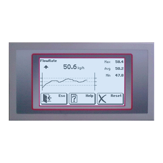
- Page 29 SECTION 4: HOURLY FLOw RATE In the main window press the section to enter the detailed window concerning the instantaneous hourly flow rate, where additional information are reported. Output trend (up, down, stable) The display shows the current hourly flow rate values, the minimum, the maximum and the arithmetic mean of the previous instantaneous hourly flow rate values represented in the graphic.
- Page 30 SECTION 7: STATE AND TIMER This display shows a message that indicates the instrument operation sta- te, and one timer (hours:minutes:seconds) relevant to the run time, that is reset upon run start. The state message in the general window indicates the STOP and RUN conditions whereas in other procedures it can assume the following data: Belt cal.
-
Page 31: Set-Up Menu Levels
3.3 - SET-UP MENU LEVELS The parameters that can be set are organised in 3 different levels: User, Technician and set-up. For each level it is possible to enable one access password for the menu. A change of the could parameters can jeopardise the machine operation and thus we recommend it to be carried out only by qualified personnel and anyway after having read the manual. - Page 32 PARAMETERS SET-UP MENU - SET-UP LEVELS PROTECTION It is possible to associate to each level a protection password that can be set through the technical menu, and it will be required to enter the relevant menu. If you set 0 as password the access to the menu is free, thus the password request is disabled. from the tECHNICAL MENU select LEVEL PROtECtION;...
-
Page 33: Parameters Tables
3.4 - PARAMETERS TABLES REGULATION PAR. Sampling Time 1001 Proport. Const. 1002 Integral Const. 1003 Dead Band 1004 Flowrate Limit 1005 I/O SELECTION 1021 Tot. Pulse Value 1022 Al. Min. Weight 1023 Alarm Out Logic 1024 Toler. Out Logic USER MENU 1025 Al. - Page 34 TECHNICAL MENU - PARAMETERS LIST COMM. PORTS TEST FUNCTION 0101 COM1 Protocol I/O TEST COM1 Baud rate 0102 SYS. SIMULATION COM1 Frame Sel. 0103 1ST. AN. OUT TEST COM2 Protocol 0104 2ST. AN. OUT TEST (OPTIONAL) COM2 Baud rate 0105 ACCESS LEVELS COM2 Frame Sel.
- Page 35 SET-UP MENU - PARAMETERS LIST SYSTEM SETUP SETUP SAVING Operat. Function 0011 (Specific Procedure) Encoder 0012 SETUP LOADING Total Batch 0013 (Specific Procedure) Input f. Master 0014 2nd Analog Out 0015 SYSTEM SETUP 3nd Analog Out 0016 SYSTEM SETUP Analog Input 0017 SAVE SETUP USB Host Port...
-
Page 36: List Of Parameters To Be Set
3.5 - LIST OF PARAMETERS TO BE SET Addr. Name Decription Unit Menù 0011 Logic Operat. Function Operating mode sel. (transmitter/adjuster) 0012 Encoder Logic System encoder availability sel. (no/yes) 0013 Total Batch Logic Totalization function with setpoint check sel. (no/yes) 0014 Input f. - Page 37 1001 Sampling Time Hourly capacity sampling time 1002 Proport. Constant Adjustment algorithm proportionality constant Coeff. 1003 Integral Constant Adjustment algorithm integration constant 1004 kg/h Dead Band Capacity gap around the Set where adjustment does not occur 1005 kg/h Flowrate Limit Capacity Setpoint tolerance 1006 Dead Band %...
- Page 38 2067 kg/h Setpoint 14 Capacity setpoint No. 14 2068 Manual Out Set14 Percentage output associated with Setpoint No.14 2069 kg/h Setpoint 15 Capacity setpoint No. 15 2070 Manual Out Set15 Percentage output associated with Setpoint No.15 3011 kg/h Flowrate Instant read, calibrated and filtered capacity 3013 Total Conveyed product total weight...
- Page 39 TECHNICAL NOTES: GENERAL TOTAL The general total counts the conveyed total weight separately from the standard total (lower level). The reset of such values is independent. The total setpoint output control can not be connected with the general total. For both totalizers the max value that can be counted is 99999999 (8 digits), and after this value it is reset.
- Page 40 TECHNICAL NOTE: ROLLERS DISTANCE The rollers distance (DR) is measured in different ways according to the type of belt the weighing bridge is installed on. The following picture shows a summary of the different types with relevant identification mode of the parameter. WEIGHING ON BELT DR corresponds to the distance between weighing bridge upstream and downstream rollers.
- Page 41 TECHNICAL NOTES ABOUT THE SYSTEM SET-UP TECHNICAL NOTE: MASTER INPUT This selection enables the flow rate setpoint continuous change function by one master. According to the selected value, this change can occur through COM2 (RS485) serial line or through analogue input. In the latter case the instrument must be provided with an analogue input optional board.
-
Page 42: List Of Parameters Prior To Commissioning
3.6 - LIST OF PARAMETERS PRIOR TO COMMISSIONING For correct working conditions of the weighing system, the main parameters to check and enter before start are explained. Par. Name Description Value Max flow rate Maximum flow rate of the system expressed in Kg/h. Programming of this parameter 0152 determines the scale and flow rate unit of measurement (see page 37), the same value corresponds also to the Scale End analogical output exit in case it works as a... - Page 43 Par. Name Description Value 1002 Proport. constant Regulation parameter (not visible in case of TRANSMITTER). It is the ratio between instant flow rate variation and speed regulation analogical signal variation. 1003 Integral constant Regulation parameter, speed signal correction intervenes each time it reaches the set number of samples in this constant.
- Page 44 Par. Name Description Value Weight timeout Maximum time in which the weight transmitted from the load cells during the run can keep 1042 the same value before generating its alarm (OUT 4). Regulation delay Delay, with respect to the run start, during which the instrument does not adjust the flow 1043 rate and keeps the starting output value.
-
Page 45: Instrument Procedure
4 - InsTRUMenT PRoceDURe 4.1 - INSTRUMENT COMMISSIONING PROCEDURE For correct working conditions of the instrument, keep to the following steps. Only qualified personnel shall carry out the procedures described below. 1. Install the instrument and connect the terminal boards as shown in the diagram in the manual. 2. -
Page 46: In-Out Test Procedure
4.2 - IN-OUT TEST PROCEDURE TECHNICAL MENU -> TEST FUNCTIONS -> IN/OUT TEST This procedure allows to display the logic outputs and inputs state and force the outputs state from the touch screen. Press the output luminous button to change (ON/OFF) the state. -
Page 47: Machine Test Procedure
4.4 - MACHINE TEST PROCEDURE TECHNICAL MENU -> MACHINE TEST Through this procedure it is possible to define one precise correspondence between the flow rate and the speed adjustment analogue output signal. In correspondence to a speed value within 20% and 80% it is possible to save the real flow rate value;... -
Page 48: System Calibration
5 - sYsTeM calIbRaTIon the weighing belt calibration is a fundamental stage to get a correct measure and shall always be carried out; it is furthermore necessary to repeat it periodically and each time you carry out mechanical adjustments on the belt. the calibration consists of two phases: 1) Zero calibration that allows to acquire the system tare and can be carried out both with moving belt (recommended procedure) and with stopped belt;... -
Page 49: Belt Calibration Dynamic Procedure
the reset procedure can also be activated by a remote control using the saved parameters only in stop conditions. the control can be transmitted by the serial line (5001 parameter), or by the logic input (input 5). the procedure modes are the same of the manual one but with set maximum resettable value (0135);... -
Page 50: Zero Static Calibration And With Sample Weight
Note: during the calibration test it is necessary to follow the rule below: if you start with empty belt you must finish with empty belt, if you start with full belt you must finish with full belt. CORRECTION FACTOR MANUAL CALCULATION AND SET-UP This function allows to manually set the “correction factor”;... -
Page 51: Mc353 Operation Alarms
It allows to enter the sample weight loaded on the belt (in Kg); usually one roller placed near the load cells axis. 5.4 - MC 353 OPERATION ALARMS During RUN the following alarms may occur, shown in the display’s dedicated area, up to the right, with a blinking icon, beyond the activation of the relevant output. - Page 52 5.5 - DENSITY CALIBRATION PROCEDURE Density calibration consist in programming parameter Specific Weight and register a weight value for “Peso Mem”. These values are used for actual density calculation according the formula indicated at the next chapter. Press box on display to setup the specific weight Press box on display to setup the actual weight DENSITY CALCULATION...
-
Page 53: Additional Functions Of Mc353
6 - aDDITIonal fUncTIons of Mc 353 6.1 - DATA LOGGER TECHNICAL MENU -> DATA LOGGER This function can be enabled by the technical menu and allows to continuously record run operative data to analyse the system behaviour over time. The provided data are the following: Actual time of the sampling period in ms TTTTT (5 car.) -
Page 54: File Loading
In case of transfer on COM2 the load function waits to receive one file whereas the saving function sends data directly to the communication port without waiting handshake operations: the receiving unit must be able to receive data when the control is activated. In case of transfer on USB pen drive, the memory support shall be entered before the activation of the saving and loading controls. -
Page 55: Receipt Print
Relay module MOD-RELE’, connected through COM2 (RS485) to the MC 353 instruments, can handle an additional 8 outputs and 4 inputs. Each MC 353 instrument can be connected to a total of 2 relay modules at the same time, handling this way up to 16 outputs and 8 inputs. -
Page 56: Serial Communication And Protocols
7 - seRIal coMMUnIcaTIon anD PRoTocols 7.1 - ASCII COMMUNICATION PROTOCOL Baud rate and format data according to the selection on the TECHNICAL MENU. RS485 interface with 2 twisted pairs. The communication protocol requires always the transmission of a string by the PC with the address of the control receiver instrument and a response string by the receiving instrument. - Page 57 In case of unavailability the instrument will send a suitable response control. COMMUNICATION STRINGS FORMAT All strings transmitted to the MC 353 have the following format; also the MC 353 response strings have the same format except the error one, the not available control string and the acknowledgement one.
- Page 58 <N> = number of setpoint (from ”1” to ”9” and from ”A” to ”F” for set point from 10 to 15) <XXXX> = flow rate set point without decimal point The MC 353 answers: ADDR “A” ACK EOT B) Flow rate setpoint reading The PC transmits: ADDR “B”...
- Page 59 G) Conveyed total setpoint reading The PC transmits: ADDR “G” <N> <XXXX> ETX <CC> EOT The MC 353 answers: ADDR “G” <XXXXXXX> <PPPPPPP> <VVVVVVV> ETX <CC> EOT Where : <XXXX> = total setpoint <PPPPPPP> = total preset without decimal point <VVVVVVV>...
- Page 60 ADDR_0 “M” <XXXX> ETX <CC> EOT This string shall contain the address 0 to be recognised. The MC 353 does not transmit any string neither in case of performed control nor in case of error. The percentage value received is related to the maximum flow rate value.
-
Page 61: Modbus Communication Protocol
7.2 - MODBUS COMMUNICATION PROTOCOL The complete list of MODBUS controls and protocol addresses are reported in the table at pages 34, 35 and 36. NOTE: The MODBUS-RTU specifications foresee that the 40001 register is allocated the address 0000. Master’s timeout duration for each query sent must be at least 25 ms. At this time add query’s transmis- sion time and the response time. -
Page 62: Profibus-Dp Communication Protocol
PROFIBUS interface may be installed either internally or externally to the instrument (in later case module S125 is used, connected through COM 1 serial port Rs422) PROFINET interface is internally installed only. Connection between MC 353 and Profibus-CONV module: Profibus-CV MC 353... - Page 63 ERROR MANAGEMENT (Ref. Par. OPERATING ALARMS) [Err. PROFIBUS] Communication failure error between Modbus and S125 module : after 5 consecutive communication time-outs. A communication reset is automatically executed, but if it fails the error is displayed and you can manually reset the error by pressing the RESET push-button. [NoCom.
- Page 64 - Programming of the whole OUTPUT DATA AREA: write the desired values in the corresponding regi- sters, then write the command for the programming of the whole AREA in the command register, based on the following command register reference table. - The OUTPUT DATA AREA page is automatically selected based on the value written in the command register.
- Page 65 INPUT DATA AREA [01] Address Variables Mapp. bytes 3027 Test Status 34-35 3028 Run Status 36-37 3029 Flow rate decimals 38-39 3030 Total decimals 40-41 3031 Weight decimals 42-43 4011 Num. Set 44-45 4012 Auto / Man 46-47 4013 Manual Out 48-49 4014 Var.
- Page 66 INPUT DATA AREA [01] Address Variables Mapp. bytes 1041 Stop Delay 110-111 1042 Timeout Peso 112-113 114-115 1043 Regolation Delay 1044 Flow Limit Delay 116-117 118-119 1045 Limit Init Delay 1063 Min. Weight 120-121 5002 Run Command Reg 122-123 7001 Test Register 124-125 INPUT DATA AREA [02]...
- Page 67 OUTPUT DATA AREAS OUTPUT DATA AREA [01] 5001 Command Register General register for H parameter programming General register for L parameter programming 7001 Test Register 4011 Set number 4012 10-11 Auto / Man 4013 12-13 Manual Out 4014 14-15 Var. Setpoint 4015 Specific gravity 16-17...
- Page 68 OUTPUT DATA AREA [03] Address Variables Mapp. bytes 5001 Command Register General register for H parameter programming General register for L parameter programming 7001 Test Register 2001 Total Set H 2002 Total Set L 10-11 2003 Total Preset H 12-13 2004 Total Preset L 14-15...
- Page 69 OUTPUT DATA AREA [06] 5001 Command Register General register for H parameter programming General register for L parameter programming 7001 Test Register Max Flowrate H Max Flowrate L 10-11 Dead Band Unit 12-13 Tolerance Unit 14-15 Real Max. Flowrate H 16-17 Real Max.
- Page 70 CUSTOM MAPING OF INPUT AND OUTPUT AREAS It is possible to configure the PROFIBUS DP and PROFINET IO field buses I/O areas, to obtain an ordered list of parameters according to the specific needs of the system. This configuration is done using a specific utility (PCWIN 75) connected to the RS232/USB port COM2 of the instrument (communication parameters selectable).
-
Page 71: Supervision Functions
7.4 - SUPERVISION FUNCTIONS The supervision functions by one PC/PLC are carried out through the COM1 communication port (RS422 / RS485 or optional Ethernet ). The communication protocol used is MODBUS RTU, with records that can be set whose addresses are listed in the parameters table and they shall be added the value 40000. -
Page 72: Repetitor Transmission Protocol
SCHEDULE Using the MODBUS-RTU and ASCII in which the instrument acts as a SLAVE, consider that: - MASTER timeout for each transmitted query must be submitted for at least 25 ms; at this time, add also the transmission time of the query and the time of receipt of the response, which depends on the baud rate. -
Page 73: Troubleshooting
8.1 - TROUBLESHOOTING Hereinafter is a list of the most frequent questions and answers relating to problems which may arise upon MC 353 electronics installation and operation. Anyway, should you have further doubts or problems, contact the technical service. Question... - Page 74 3- Check correct coupling The instrument displays - Encoder does not send between belt drum and encoder ALL-ENCODER pulses to instrument shaft. Check also that shaft is turning. 5- Check for the presence of The instrument displays - No material material on the weighing system ALL-MIN.WEIGHT 6- Execute or repeat the ZERO...
- Page 75 13- Try to change adjustment Instrument cannot keep - Wrong flow rate adjustment the set SET POINT and (proportional and integration) and tolerance parameters and flow rate tolerance continues entering an OUT-OF-TOLERANCE parameters alarm 14- Create on belt a layer of - Conveyed material is not material as even as possible extracted continuously...
-
Page 76: Configuration And Test Form
- SCHEDA DI CONFIGURAZIONE E COLLAUDO MC 353 - - MC 353 CONFIGURATION AND TEST FORM - Cliente (customer): Commessa (job): Impianto (system): Nazione (country): Release: Funzionamento (appliance for): REGOLATORE (FLOW REGULATION) S/n: TOTALIZZATORE (FLOW TOTALIZATION) Uscita analogica 1 (analogic output 1): 0÷20mA... - Page 77 Pag. 77...
- Page 78 PAVONE SISTEMI S.R.L. Via Tiberio Bianchi 11/13/15, 20863 Concorezzo (MB), ITALY T 0039 039 9162656 F 0039 039 9162675 W en.pavonesistemi.it Industrial Electronic Weighing Systems since 1963...
Need help?
Do you have a question about the MC 353 and is the answer not in the manual?
Questions and answers