Table of Contents
Advertisement
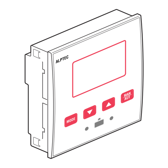
Automatic Power Factor Controller
ALPTEC 3.2 - ALPTEC 5.2
Index
Introduction....................................................................................................................................................................................................................... 2
Description....................................................................................................................................................................................................................... 2
Keyboard functions ........................................................................................................................................................................................................... 2
Display indications............................................................................................................................................................................................................ 2
Operating modes .............................................................................................................................................................................................................. 3
Measures.......................................................................................................................................................................................................................... 3
Keypad lock ...................................................................................................................................................................................................................... 4
Expandability .................................................................................................................................................................................................................... 5
IR programming port ........................................................................................................................................................................................................ 5
Parameter setting (setup) with PC.................................................................................................................................................................................... 5
Parameter setting (setup) from front panel ....................................................................................................................................................................... 6
Rapid CT set-up ............................................................................................................................................................................................................... 7
Parameter table ................................................................................................................................................................................................................ 7
Alarms ............................................................................................................................................................................................................................ 12
Alarm description............................................................................................................................................................................................................ 12
Commands menu ........................................................................................................................................................................................................... 12
CX02 Dongle usage ....................................................................................................................................................................................................... 13
Installation ...................................................................................................................................................................................................................... 13
Wiring diagrams.............................................................................................................................................................................................................. 13
Terminals position........................................................................................................................................................................................................... 15
Mechanical dimensions and front panel cutout (mm) ..................................................................................................................................................... 15
Technical characteristics................................................................................................................................................................................................. 15
Warning!
- Carefully read the manual before the installation or use.
- This equipment is to be installed by qualified personnel, complying to current
standards, to avoid damages or safety hazards.
- Before any maintenance operation on the device, remove all the voltages from
measuring and supply inputs and short-circuit the CT input terminals.
- Products illustrated herein are subject to alteration and changes without prior notice.
- Technical data and descriptions in the documentation are accurate, to the best of our
knowledge, but no liabilities for errors, omissions or contingencies arising there from
are accepted.
- A circuit breaker must be included in the electrical installation of the building. It must
be installed close by the equipment and within easy reach of the operator. It must be
marked as the disconnecting device of the equipment: IEC /EN 61010-1 § 6.11.2.1.
- Clean the instrument with a soft dry cloth; do not use abrasives, liquid detergents or
solvents.
A Group brand
Advertisement
Table of Contents

Subscribe to Our Youtube Channel
Related Manuals for Alpes Technologies ALPTEC 3.2

Summary of Contents for Alpes Technologies ALPTEC 3.2
-
Page 1: Table Of Contents
Automatic Power Factor Controller ALPTEC 3.2 – ALPTEC 5.2 A Group brand Warning! – Carefully read the manual before the installation or use. – This equipment is to be installed by qualified personnel, complying to current standards, to avoid damages or safety hazards. -
Page 2: Introduction
Introduction The ALPTEC automatic power factor control unit has been designed to offer state-of-the-art functions for power factor compensation applications. Built with dedicated components and Extremely compact, the ALPTEC combines the modern design of the front panel with practical installation and the possibility of Extansion from the rear, where one EXT series module can be slotted. -
Page 3: Operating Modes
Operating modes There are two possible operating modes, listed below: – If this display appears at the power On DO NOT USE THE ARROW ▲ ▼ – Press MODE during 3 seconds to exit this page and enter the setup parameter page. Please refer to page xx "Parameter settings from the front panel"... -
Page 4: Keypad Lock
Measures (continued) – Below is a table with the measurements displayed. Measure Icon Description Δ kvar Delta–kvar Kvars needed to reach the cosphi setpoint. If delta-kvar is positive cpacitors need to be inserted, if negative to be disconnected. kvar Total kvar of the plant. Δ... -
Page 5: Expandability
Expandability – Thanks to expansion bus, the ALPTEC can be expanded with one EXT… series module. – To insert an Extansion module: • Remove the power supply to ALPTEC. • Remove the protecting cover of the Extansion slot. • Insert the upper hook of the module into the fixing hole on the top of the expansion slot. •... -
Page 6: Parameter Setting (Setup) From Front Panel
Parameter setting (setup) from front panel To access the programming menu (setup): – Prepare the controller in MAN mode, to disconnect all the steps. – From the normal measurement display, press MODE for 3 seconds to recall the main menu. SET is displayed on the main display. –... -
Page 7: Rapid Ct Set-Up
Rapid CT set-up – When the CT value is not known and only used at the moment of the installation, the P.01 parameter for CT primary can remain set at OFF while all the others can be programmed. – In this case, during the system installation and once the controller is powered up, the display will show a flashing CT (Current Transformer). By pressing ▲ ▼ the CT primary can be set directly. - Page 8 Parameter table (continued) P01 – VThe value of the primary current transformer. Example: with CT 800/5 set 800. If set to OFF, after the power-up the device will prompt you to set the CT and allow direct access to this parameter. P.02 - Value of the secondary of the current transformers.
- Page 9 Parameter table (continued) Description RANGE P.37 Fan start temperature ° 0 .. 100°C (32...212°F) P.38 Fan stop temperature ° 0 .. 100°C (32...212°F) P.39 Temperature alarm threshold ° 50 .. 100°C (122...212°F) P.40 Step failure alarm threshold OFF / 25…100 P.41 Maximum voltage alarm threshold N.A.
- Page 10 P.33 - Threshold beyond which the integral delay for tripping of the overload alarm is zeroed, causing the immediate intervention of the A08 alarm. P.34 – P.35 – Data of VTs eventually used in the wiring diagrams. Parameter table (continued) P.37 –...
- Page 11 P.78 Delay UoM A06 P.79 Alarm activation A07 DISC P.80 Alarm delay A07 0-240 P.81 Delay UoM A07 P.82 Alarm activation A08 DISC P.83 Alarm delay A08 0-240 P.84 Delay UoM A08 P.85 Alarm activation A09 DISC P.86 Alarm delay A09 0-240 P.87 Delay UoM A09...
-
Page 12: Alarms
Alarms – When an alarm is generated, the display will show an alarm icon, the code and the description of the alarm in the language selected. – If the navigation keys in the pages are pressed, the scrolling message showing the alarm indications will disappear momentarily, to reappear again after a few seconds. -
Page 13: Cx02 Dongle Usage
CX02 Dongle usage – The Cx02 dongle offers WiFi Access point capability for connection to PC, Tablet or smartphones. In addition to this function it also offer the possibility to store and transfer a block of data from/to the DCRL. –... - Page 14 Wiring diagrams (continued) Single-phase wiring Typical diagram - do not represent the internal connexion of our capacitor banks SINGLE-PHASE CONNECTION Wiring configuration for single-phase applications Voltage measure 1 phase voltage reading L1-N Current measure L1 phase Phase angle offset Between V (L1-N ) and I (L1) 0°...
-
Page 15: Terminals Position
Terminals position ALPTEC3 ALPTEC5 Mechanical dimensions and front panel cutout (mm) Technical characteristics Supply Measuring accuracy Rated voltage Us Line voltage ±0.5% f.s. ±1digit 100 – 440 VA 110 – 250 V= Relay output: ALPTEC3.2 OUT 1 - 2 / ALPTEC5.2 OUT 1 - 4 Operating voltage range 90 –... - Page 16 Technical characteristics (continued) Ambient operating conditions Operating temperature -20 - +60°C Storage temperature -30 - +80°C Relative humidity < 80 % (IEC/EN 60068-2-78) Maximum pollution degree Overvoltage category Measurement category Climatic sequence Z/ABDM (IEC/EN 60068-2-61) Shock resistance 15 g (IEC/EN 60068-2-27) Vibration resistance 0,7 g (IEC/EN 60068-2-6) Connections...
Need help?
Do you have a question about the ALPTEC 3.2 and is the answer not in the manual?
Questions and answers