
Subscribe to Our Youtube Channel
Summary of Contents for Purelogic PLDS880
-
Page 1: Table Of Contents
PLDS880 Servo-step motor DSP driver O P E R AT I O N A L M A N U A L 01. General Provisions 02. Scope of delivery 03. Specifications 04. Driver installation and ventilation 05. Driver features 06. Driver control signal connection 07. -
Page 2: General Provisions
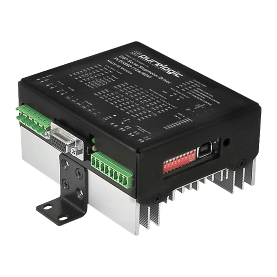
General Provisions PLDS880 is a DSP processor based digital driver of Servo-Step Motor (SSM) with possibility of driver parameter PC adjustment via USB interface. Driver may work both in servo mode and SM common driver mode without encoder. In servo mode SSM is controlled as fully functional servo motor with position and speed control. -
Page 3: Scope Of Delivery
PLDS880. Servo-step motor DSP driver Scope of Delivery • PLDS880 step motor DSP driver - 1 piece • Operational Manual - 1 piece Specifications Module power supply voltage 18…80V (typical value 70V) SSM operating current 2А…10А 1...512 SSM step division (micro step) SB encoder support Diff.inlet, 500-1024 pulse/rev... - Page 4 03. Specifications Figure 1. PLDS880 SSM driver dimensions 8 (800) 555 63 74 www.purelogic.ru...
-
Page 5: Driver Installation And Ventilation
PLDS880. Servo-step motor DSP driver Driver Installation and Ventilation To ensure optimal thermal conditions equipment inside NC control rack shall be mounted according to diagram below: >25mm Драйвер Драйвер >100mm >100mm — Вентиляторы — Направление воздушного потока Драйвер –Driver Вентиляторы - Fans Направление... -
Page 6: Driver Features
• Heating protection (temperature sensor) • Integral SSM mid-frequency resonance compensator. • Integral damper • ERROR driver trouble signal opto-isolated output • SSM connection easy-to-use dismountable terminals/ • STEP frequency, emergency, driver power supply indication. 8 (800) 555 63 74 www.purelogic.ru... - Page 7 PLDS880. Servo-step motor DSP driver Control Signal Connection Module is controlled by standard STEP/DIR and ENABLE signals. Signals are transmitted at differential opto-isolated inlets. Yellow LED is illuminated and driver is ON at generated ENABLE signal. Yellow LED is flashing and SSM is rotating at produced STEP frequency.
-
Page 8: Current And Voltage Selection
SSM winding specified operating current. SSM operating current is set by corresponding value in configuration program (Work_Current_ Min and Work_Current_Max). If no STEP signal is available more than 1 second driver is switched to sleep mode (AUTO-SLEEP mode) and reduces winding current. 8 (800) 555 63 74 www.purelogic.ru... - Page 9 PLDS880 perfectly fits for controlling of Purelogic R&D PL57/PL86 Series bi-polar and unipolar step motors. Purelogic R&D SSM is connected to driver according to Fig. 3 (terminals PH1.1(+A), PH1.2(-A) and PH2.1(+B), PH2.2(-B) and encoder connector). Encoder connector contact designation is also shown at Fig.
-
Page 10: Driver Ssm Connection
08. Driver SSM connection Блок питания – Power Supply Unit Шаговый двигатель – Step motor Устройство коммутации – Switching device 8 (800) 555 63 74 www.purelogic.ru... - Page 11 PLDS880. Servo-step motor DSP driver Fig. 3 Driver connection general arrangement drawing Edition of 09.11.2016...
- Page 12 08. Driver SSM connection разъем DHS15F на кабеле DHS15F-3м и на драйвере PLDS880 разъем DHS15M на шаговом двигателе Fig. 4 Driver motor connection Красный Зеленый Желтый Red Green Yellow Синий Черный Белый Blue Black White Connector Разъем На кабеле At cable И...
- Page 13 SW8 switch. If it is in lower position (ON position) mode Autosleep is enabled. If it is in upper position Autosleep is disabled. PLDS880 driver operation mode is selected with SW9 and SW10 switches. At started STEP signal internal generator SSM speed and direction may be controlled by potentiometer STEP GENERATOR.
-
Page 14: Pc Driver Connection Via Usb Interface
10. PC driver connection via USB interface Fig. 6. SM and SSM step division selection diagram Driver PC connection via USB PLDS880 driver may be connected to PC via galvanic isolated USB port for parameter adjustment. For PLDS880 module PC correct operation configuration program shall be downloaded and virtual COM-port driver shall be installed using link: http://www.purelogic.ru/files/downloads/SOFT/... - Page 15 PLDS880. Servo-step motor DSP driver Fig.8 Virtual COM-port in Device Manager Панель управления – Домашняя страница Control panel –Homepage Диспетчер устройств Device manager Настройка удаленного доступа Remote access adjustment Защита системы System additional parameters Диспетчер устройств Device manager Панель управления – Домашняя страница...
- Page 16 Устройства HID (Human Interface Devices) HID (Human Interface Devices) devices Центр поддержки Support Center Центр обновления Windows Window Update Счетчики и средства производительности Performance Information and Tools Fig. 9 Device connection via virtual COM-port 8 (800) 555 63 74 www.purelogic.ru...
- Page 17 PLDS880. Servo-step motor DSP driver Fig. 10 Program main window If COM-port is selected correctly and PLDS880 is ON driver parameters are displayed in program main window (Fig.10). “Status: OK” will be in status line. Driver parameter adjustment in configuration program SSM standard profiles prepared by Purelogic R&D are recommended...
-
Page 18: Driver Parameter Adjustment By Configuration Program
7 memory banks “0”….”6” are available. • Save/Download profile (current parameters) to/from file. • Download standard profiles from non-volatile memory. Standard profiles are developed by Purelogic R&D specialists for certain type SSM. If Customer changes profile and wishes driver to operate with it at every start then it is required to save profile in driver non-volatile memory bank “0”... - Page 19 PLDS880. Servo-step motor DSP driver • “Settings → Information” is description of configuration program operation, driver parameters. • “Settings → Language” is selection of configuration program interface language. Description of adjustable parameters: • “Work_Current_Max” is maximum operating current of step motor phases, peak current.
-
Page 20: Driver Error And Indication
Celsius degrees (0C). Temperature sensor is installed in DSP processor. • “Temp_Heatsink” is radiator actual temperature. It is measured in Celsius degrees (0C). Temperature sensor is installed at radiator. • “FLAG_STEP” is STEP optical inlet actual status. “1” is STEP 8 (800) 555 63 74 www.purelogic.ru... - Page 21 PLDS880. Servo-step motor DSP driver command signal frequency ON. “0” is STEP command signal frequency OFF. • “FLAG_DIR” is DIR optical inlet status. “1” is step motor shaft clockwise rotation. “0” is counter clockwise rotation. • “FLAG_ENB” is driver actual status ON/OFF. “1” is ON, “0” is OFF.
-
Page 22: Warranty
3. Guarantee service procedure 3.1. Guarantee service is provided by testing (checking) of Goods declared defects. 3.2. Guarantee repair is performed after defect confirmation. 4. Guarantee does not cover glass, electric lamps, starters and consumables and also: 8 (800) 555 63 74 www.purelogic.ru... - Page 23 PLDS880. Servo-step motor DSP driver 4.1. Goods with damages due to improper transportation and storage conditions, misconnection, off-design operation or conditions that are not specified by Manufacturer (including excess temperature and humidity), damages due other conditions (power supply voltage surges, natural disasters etc) and having mechanical and thermal damages.
- Page 24 Please note that this documentation is subject to change due to the continuous technical improvement of our products. You can always download the latest version on our website www.purelogic.ru w w w. p ure lo g i c .r u Contact information...
Need help?
Do you have a question about the PLDS880 and is the answer not in the manual?
Questions and answers