Advertisement
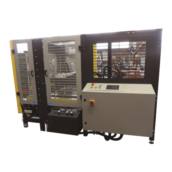
SM44 HS
NASTRATRICE AUTOMATICA
AUTOMATIC CASE SEALING MACHINE
MACHINE ENRUBANNEUSE AUTOMATIQUE
AUTOMATISCHE KARTONVERSCHLIESSMASCHINE
PRECINTADORA AUTOMATICA
MANUALE DI ISTRUZIONI E PARTI DI RICAMBIO
INSTRUCTIONS MANUAL AND SPARE PARTS LIST
MANUAL D'INSTRUCTIONS ET PIECES DETACHEES
BEDIENUNGSANLEITUNG UND ERSTAZTEILLISTE
MANUAL DE INSTRUCCIONES Y RECAMBIOS
Cod. pubbl.: SMB00087K.1
Advertisement
Table of Contents

Summary of Contents for siat SM44 HS
- Page 1 SM44 HS NASTRATRICE AUTOMATICA AUTOMATIC CASE SEALING MACHINE MACHINE ENRUBANNEUSE AUTOMATIQUE AUTOMATISCHE KARTONVERSCHLIESSMASCHINE PRECINTADORA AUTOMATICA MANUALE DI ISTRUZIONI E PARTI DI RICAMBIO INSTRUCTIONS MANUAL AND SPARE PARTS LIST MANUAL D’INSTRUCTIONS ET PIECES DETACHEES BEDIENUNGSANLEITUNG UND ERSTAZTEILLISTE MANUAL DE INSTRUCCIONES Y RECAMBIOS...
-
Page 2: Safety
- E-Mail: siat@siat.com Instruction manual for the use, maintenance, safety, shipment, storage, unpacking, set-up, repairing, trouble shoo- ting, spare parts and disposal concerning the case sealing machine model SM44 HS. This publication is property of SIAT S.P.A. Via Puecher, 22 - 22078 TURATE (CO) - ITALY Tel. -
Page 3: Table Of Contents
Machine use PTFE Polytetrafluorethylene 12.3 Tape replacement Polyvinylchloride 12.4 Cleaning Ref. reference mark 12.7 Trouble shooting SIAT SPA Società Internazionale Applicazioni Maintenance Tecniche (Società per Azioni) 13.5 Lubrication Tav. Illustration 13.9 Blade replacement 13.10 Belt replacement 13.11 Adjustment of belt tension... - Page 4 1-INTRODUCTION HOW TO READ AND USE THE INSTRUCTION MANUAL IMPORTANCE OF THE MANUAL 1.2.1 The manual is an important part of the machine; all information contained herein is intended to enable the equip- ment to be maintained in perfect condition and operated safely. Ensure that the manual is available to all ope- rators of this equipment and is kept up to date with all subsequent amendments.
- Page 5 Ampere Model Serial Number Hertz Type Volt Phase FOR AFTER-SALE SERVICE AND SPARE PARTS PLEASE APPLY TO: AGENT/DISTRIBUTOR OR LOCAL AFTER SALE SERVICE: Via Puecher, 22 22078 TURATE (CO) - ITALY Tel. 02-964951 Fax. 02-9682239 E-mail siat@siat.com February 2016 ENGLISH...
- Page 6 Buyer shall indemnify and hold Seller harmless against any claim by third parties resulting from failure to comply with the aforesaid laws and standards. SIAT S.p.A. Via Puecher, 22 - 22078 TURATE (CO) ITALY - Tel. 02964951 - Fax 029689727 - http://www.siat.com - Email: siat@siat.com...
- Page 7 3-SAFETY GENERAL SAFETY INFORMATION Read all the instructions carefully before starting the work with the machine; please pay particular attention to sections marked by the symbol The machine is provided with a complete safety protection and with a two LOCKABLE EMERGENCY STOP BUTTON placed on the same protection and on the control panel;...
- Page 8 3-SAFETY SKILL 2 MECHANICAL MAINTENANCE TECHNICIAN This operator is trained to use the machine as the MACHINE OPERATOR and in addition is able to work with the safety protection disconnected, to check and adjust mechanical parts, to carry out maintenance operations and repair the machine.
- Page 9 3-SAFETY NUMBER OF THE OPERATORS The operations described hereinafter have been analized by the manufacturer; the number of operators shown for each operation is suitable to perform it in the best way. A smaller or larger number of operators could be unsafe. OPERATORS’...
- Page 10 3-SAFETY RESIDUAL HAZARDS The case sealer SM44 HS has been designed following the EC direc- tives, and incorporates various safety protections which should never be removed or disabled. Notwithstanding the safety precautions conceived by the designers of the machine, it is essential that the operator and service personnel be warned that the following uneliminable residual hazards exis WARNING! Tape cutting blades.
- Page 11 - Clean the machine using only dry cloths or light detergents. Do not use solvents, petrochemicals etc. - Do not modify the machine or any part of it. The manufacturer will not be responsible for any modifications. - We advise to apply directly to Siat for modifications. - Follow carefully the installation instructions of this manual.
- Page 12 3-SAFETY Shows the running direction of the belts. Label code: 3.0.01040.96A Show the earth wire connection point on the machine frame. Label code: 3.0.01039.96A Caution!: High voltage Label code: 3.0.01100.96A Tape threading path for upper taping unit. Label code: 3.0.01023.96A with for- Compulsory position to lift the machine ktrucks or other suitable raising equipment.
- Page 13 4 - PRELIMINARY INFORMATION GENERAL DESCRIPTION OF THE MACHINE The SM44 HS case sealer with side drive belts is designed to seal boxes by applying two tape strips on the top and bottom flaps simultaneously. No operator is required. The machine adjusts itself automatically to the case size and folds the 4 upper flaps. The introduction of the cases into the machine is performed by the indexing system AS24.
- Page 14 4-PRELIMINARY INFORMATION MAIN COMPONENTS The infeed conveyor is composed of: The machine is composed of: n. 1 n. 1 frame frame n. 4 n. 4 adjustable legs adjustable legs n. 1 n. 2 electric motor columns n. 1 n. 2 motorized belt taping units n.
- Page 15 4-PRELIMINARY INFORMATION OVERALL DIMENSIONS February 2016 ENGLISH...
- Page 16 5-SHIPMENT - HANDLING - STORAGE MACHINE TRANSPORTATION AND HANDLING The machine and the infeed conveyor are shipped in 2 separate pac- kings, fixed on a wooden pallet. They can be lifted with a normal fork lift. The standard packing is suitable for surface and air transportation. Oversea packing on request.
-
Page 17: Unpacking
6-UNPACKING Cut the polypropylene straps. Use a cutter to remove the part of the carton fixed by the staples along the entire perimeter of the packing. (Otherwise remove the staples by using a suitable tool) After having cut the carton or removed the staples, lift the packing up in order to free the machine. - Page 18 To lift the conveyor, position the lift forks where there are the labels on front or back side and remove the pallet. Conveyor weight: 90 kg LH side PACKING DISPOSAL The packing of the machine Mod. SM44 HS is composed of: wooden pallet carton box wooden supports...
-
Page 19: Installation
7-INSTALLATION 7.0. SAFETY MEASURES Read carefully chapter 3. 7.1. ENVIRONMENTAL CONDITIONS REQUIRED -Temperature min. = 5 °C; max. 40 °C -Umidity min 30%; max. 80% -Dust free environment 7.2. SPACE REQUIRED FOR MACHINEOPERATION AND MAINTENANCE Min. distance from the wall: A = 1500 mm; B = 1000 mm; Min. - Page 20 Support brackets (upper and bottom); 2+2 socket head screws each bracket. CONNECTION BETWEEN THE INDEXING UNIT AS24 AND THE MACHINE SM44 HS Lift the indexing unit by placing the forks under the points where the labels are. 7.6.1 Move the indexing unit to the machine and fix it using the screws pre- viously removed.
- Page 21 7-INSTALLATION EMERGENCY STOP BUTTON Furthermore mount the complete bracket with emergency stop but- ton. PNEUMATIC CONNECTION Connect air pipes from the sealing machine to the conveyor centring guides cylinder connectors and to infeed conveyor cylinders. Fitting acronyms shown in the picture identify the pipes number coming from the machine.
- Page 22 7-INSTALLATION 7.11 Carton sealer front box Box CA1 Cables n.3 and 6 Cable n. 6 Cable n. 3 Carton sealer front box Box CA2 Cable n. 6 Connectors: W70(SP1) Pressostat W73 Cylinder sensors W77 Motor February 2016 ENGLISH...
- Page 23 7-INSTALLATION 7.12 Carton sealer rear box Cable n. 5 Indexing unit box and vertical axes motors Cable n.4 Connectors: W72 – SQ32 Cylinder sensor W71 – SQ30/SQ31 Cylinder W8 – Y Cylinder W76-76 motor + ground wire on the fixing screw February 2016 ENGLISH...
- Page 24 7-INSTALLATION Connection of indexing unit photocells B10, B1, B2. Connect the photocells B10, B1 connector to the plug. Connect the cables with connector coming from the machine to the pho- tocells B2-B13. February 2016 ENGLISH...
-
Page 25: Controls
7-INSTALLATION 7.13 PRELIMINARY ELECTRIC CHECK-OUT Before connecting the machine to the mains please carry out the following operations: 7.13.1Make sure that the socket is provided with a ground protection circuit and that both the mains voltage and fre- quency meet the indications on the name plate of the machine. 7.13.2Check that the connection of the machine to the mains meets the provisions of law and/or the safety regulations in your country. - Page 26 8-CONTROLS 8.1 CONTROL BOARD 1. Main switch 2. Voltage warning light 3. Auxiliaries push button 4. Stop button 5. Start button 6. Touch screen control panel 7. Warning (flashing light + buzzer) 8. Emergency stop button REAR BOX 1 Centering guide pressure regulator 2.
- Page 27 9-OPERATION Turn on the air to the machine by the ON/OFF valve; set the main switch in ON position; close the safety guards; release the EMERGENCY STOP button; press Auxiliaries button and Start Button (if there are no alarm signalling). Start button activation: motors start (machine and indexing unit) and lifting of the indexing unit drive belt.
-
Page 28: Operation
9-OPERATION 9.3. OPERATION MODES DESCRIPTION The carton sealer works only in automatic: closed safety protection, free emergency stop button, enabled control panel and start button activated, open compressed air circuit. MACHINE START: - Press auxiliaries button (3); verify the lighting the incorporated pilot lamp. - Page 29 9-OPERATION Reset as necessary after intervention for the elimination of the problem that caused the alarm signalling. Press B A: Main page B: Alarm reset C: Reset acoustic signalling D: Alarms log Return to main menu mode (A). E: Alarms page F: Machine general reset G: Page mode of manual machine axes drive H: Page operation automatic cycle...
- Page 30 9-OPERATION - Mode of page of operation automatic cycle - In this condition the machine results ready for the star- ting of the sealing cycle as foreseen. Q R M J- Box counter (total non resettable) K: Box counter (partial resettable) L: Indexing unit vertical axe (only visualization) M: Indexing unit horizontal axe (only visualization) N: Machine vertical axe (only visualization)
- Page 31 9-OPERATION UNIT OF PARAMETERS DESCRIPTION MEASURE mm/’ Origin research speed vertical axis AXIS HOME SEARCH SPEED (FIRST PHASE) mm/’ Origin offset moving speed vert. axis SENSOR HOME SEARCH OFFSET SPEED (SECOND PHASE) mm/’ Manual speed MANUAL AXIS SPEED Vertical position range SAME BOX ACCEPTANCE VALUE (VERTICAL) Horizontal position range SAME BOX ACCEPTANCE VALUE (HORIZONTAL)
- Page 32 9-OPERATION 9.4 ALARM SIGNALIZATIONS -000 Emergency -001 Air pressure -002 Min. guides closing -003 Thermal Overload QM1 -004 Thermal Overload QM2 -005 Thermal Overload QM3 -006 Thermal Overload QM4 -009 Origin TI vert. missing -010 Origin TO vert. missing -011 TI horizontal not ready -012 Origin TI horiz.
-
Page 33: Safety Devices
10-SAFETY DEVICES OF THE MACHINE 10.1 SAFETY GUARD It limts the access to the machine, protecting the operator from the mo- ving parts. 10.2 BLADE GUARDS Both the top and bottom taping units have a blade guard. 10.3 BELT GUARDS The drive belts are protected by safety covers on their external sides and by rigid elements on the exit side. -
Page 34: Set-Up And Adjustments
11-SET-UP AND ADJUSTMENTS 11.0 SECURITY ll the operations to prepare and adjust the machine must be made with the E-stop locked. 11.1. TAPE LOADING ON THE TOP UNIT Insert a tape roll on the drum and push it fully forward. Attach the tape leg to the threading tool (supplied with the tools kit). - Page 35 11-SET-UP AND ADJUSTMENTS 11.2 TAPE LOADING ON THE BOTTOM UNIT Remove the bottom taping unit from its housing and put it on a working bench; -Put a tape roll on the drum and thread the tape through the unit as shown on the label in the same manner as for the top unit;...
- Page 36 11-SET-UP AND ADJUSTMENTS 11.6 MAIN PRESSURE REGULATOR A) it adjusts the entry working pressure B) gauge to read the entry air pressure Optimal working pressure: 6 BAR Feeding tube diameter: 10 mm N.B.: in case the working pressure is below 6 BAR or the feeding tube has a small diameter, some malfunctions can happen! (es: the upper group comes down, the rear flap folder works but the machine stops) 11.7 CENTERING GUIDES PRESSURE...
- Page 37 11-SET-UP AND ADJUSTMENTS 11.9 BOX HEIGHT PICK-UP 3) Pressure regulator with built-in pressure gauge. The pressure regulator 3 adjusts the pressure according to the board strength. -Decrease in case of light boxes. -Increase in case of strong boxes. -Minimum pressure must be adjusted so that the paddle returns auto- matically in position once the box is passed.
- Page 38 11-SET-UP AND ADJUSTMENTS 11.10 PNEUMATIC SPEED REGULATORS A) Side belts opening-closing speed regulators B) Centering gudes (infeed conveyor) speed regulators Side belts opening-closing speed regulators These are not common operations. They have to be made only when it has been necessary to work on the pneumatic cylinder. To change the speed, do as follows: unscrew the locking nut 1 turn the knob 2 clockwise to reduce the belts closing speed;...
- Page 39 11-SET-UP AND ADJUSTMENTS 11.11 SPEED REGULATORS OF THE REAR FLAP FOLDER These are not common operations. They have to be made only when it has been necessary to work on the pneumatic cylinder. To change the speed, do as follows: The speed of the rear flap folder unit can be akjusted by the flow regula- tors mounted on the pneumatic cylinders..
-
Page 40: Machine Use
12 - MACHINE USE 12.1 OPERATOR CORRECT WORKING POSITION 12.2 MACHINE STARTING - Close the side safety guards - Release the E-stops - Give air to the circuit - Turn the main switch in ON position - Press the AUXILIARIES button - Press the RESET button - Press the START button 12.3 PRODUCTION STARTING... - Page 41 12 - MACHINE USE 12.5 CLEANING fore carrying out any cleaning or maintenance operation stop the ma- chine by pressing the OFF button on the main switch. Disconnect the electric power and disconnect pneumatic circuit through valve A. CLEANING - Skill 1 operator Use dry clothes or light detergents.
- Page 42 12 - MACHINE USE 12.8 TROUBLE SHOOTING SITUATION CAUSE SOLUTION TROUBLE The side belts are not correctly posi- Check the position. tioned. Tape is not centered on the box. The box flaps are not centered. Check the flaps dimensions; flaps must be equal. Tape is not positioned in the center Adjust the tape position.
- Page 43 13-MAINTENANCE 13.0 SAFETY MEASURES (See section 3) Carrying out maintenance and repairs may require to work in dangerous situa- tions. This machine has been designed making reference to the standards EN292 and EN292/2. 13.1 Tools kit and SPARE parts SUPPLIED WITH THE MACHINE 1 N.1 blade (spare blade for taping unit;...
- Page 44 13-MAINTENANCE 13.4 SECURITIES CH ECK-UP 1 Tape units blade guards; 2 Lockable emergency stop push-buttons; 3 Rigid protection plate mounted on the side drives; 4 Safety guards; 13.5 MACHINE LUBRICATION Lubricate quarterly with grease/Metal/metal (see paragraph 13.6): Slide cross bar ball guides for side drives (grease nipples on the blocks) ;...
- Page 45 13-MAINTENANCE 13.6 SUGGESTED PRODUCTS FOR LUBRICATION GREASE TYPE: METAL/METAL: B.C.190 HEAVY DUTY (otherwise grease for chains and bearings) METAL/PLASTIC: PLATE MASTER M+L (molybdenum grease and PTFE for plastic and metallic materials) OIL TYPE: regular lubricating oil or general purpose spray lubricant. 13.7 LUBRICATION OF THE TAPING UNIT Lubricate monthly with oil the points shown on Picture.
- Page 46 13-MAINTENANCE 13.10 SIDE DRIVE BELTS REPLACEMENT Skull 2 operator. Notice: in order to convey the case correctly, it is necessary that both belts have the same level of wear. Remove the plug from the mains and take the air off the circuit. Disconnect the Klingel plug from the socket.
- Page 47 13-MAINTENANCE Remove the locking screws and the protection covers. Loosen the tensioning screws. Release the nut of the tensioning plate. Remove and replace the drive belt. WARNING! Before setting the new belt, check the wear of the orange plastic rings on the drive pulleys: replace them if they are worn out.
- Page 48 13-MAINTENANCE 13.11 ADJUSTMENT OF THE BELTS TENSION Check the tension of the belt by pulling it outwards in the middle. A force of 3,5 kg should produce a gap of 25 mm (1 inch) between the belt and the frame. February 2016 ENGLISH...
- Page 49 LIST OF THE MAINTENANCE OPERATIONS CARRIED OUT ON THE MACHINE Date Description of operation February 2016 ENGLISH...
- Page 50 14-ADDITIONAL INSTRUCTIONS 14.1 INSTRUCTIONS FOR SCRAPPING AND DISPOSAL OF THE MACHINE The machine is made of the following materials: - steel frame - nylon conveyor rollers - PVC drive belts - nylon pulleys In order to dispose of the above materials please comply with the law in force in your country. 14.2 INSTRUCTIONS ON EMERGENCY SITUATIONS In case of danger/fire: disconnect the electric power.
-
Page 51: Enclosures
15-ENCLOSURES 15.1 STATEMENT OF CONFORMITY to the Directives on Machinery 2006/42 CE. 15.2 SAFETY LABELS The safety labels are important for the correct use of the machine. In case any label is damaged or removed, it is responsibily of the user to replace it immediately. 15.3 EMISSIONS OF RADIATIONS, GAS, VAPOURS AND DUST Nothing to report... - Page 53 MACHINE ENRUBANNEUSE AUTOMATIQUE AUTOMATISCHE KARTONVERSCHLIESSMASCHINE PRECINTADORA AUTOMATICA PARTI DI RICAMBIO SPARE PARTS LIST PIECES DETACHEES ERSTAZTEILLISTE RECAMBIOS SIAT S.p.A. - Via Puecher, 22 - 22078 TURATE (CO) ITALY - P.O. BOX 1 Tel. 02-964951 - Telefax 02-9689727 http://www.siat.com - E-Mail: siat@siat.com...
- Page 54 Product description Figura Descrizione figura Prodotto Descrizione Prodotto 15389 Gruppo bancale SM44-HS Nastratrice Posizione Unità mis. Codice SIAT Definizione S4510005647A Bancale c/inserti S4304737ZZZ Gamba con piedino SA2 SR4 S4304788ZZZ Gamba con piedino AS80 S350259895A Gamba scorrevole estrusa SA2 SR4 S300098295A Righella millim.
- Page 56 Product description Figura Descrizione figura Prodotto Descrizione Prodotto 15390 Traversa motorizzazioni SM44-HS Nastratrice Posizione Unità mis. Codice SIAT Definizione S4510003147A Traversa guida motorizzazioni c/inserti S4710003200A Pignone 3/8" Z35 c/cuscinetto S3310004292A Pignone Z=35 p=3/8" S3400156A Cuscinetto 6005-2RS1 SKF S340019192Z Anello arresto per foro 47...
- Page 57 SM44-HS 15390 Fig. Giu. 2010...
- Page 58 Product description Figura Descrizione figura Prodotto Descrizione Prodotto 15391 Pressatori laterali SM44-HS Nastratrice Posizione Unità mis. Codice SIAT Definizione S3210014247A Piastra inf. dx pressatori laterali S3210014300A Piastra inf. sx pressatori laterali S3210014547A Piastra sup. pressatori laterali S3310004147A Blocchetto unione piastre S340005393Z...
- Page 59 SM44-HS 15391 Fig. Giu. 2010...
- Page 60 Figura Descrizione figura Prodotto Descrizione Prodotto 15392 Chiudifalda posteriore SM44-HS Nastratrice Posizione Unità mis. Codice SIAT Definizione SBA0010104V Supporto chiudifalde sup. ass. SM44-HS SBA0010105V Braccio chiudifalde ass. SM44HS S4304333ZZZ Flagia con dadi e cuscinetti SBC0017120T Perno braccio chiudifalde sup. SM44HS S471229100A Chiudifalda post.
- Page 61 21 20 18 42 36 33 18 19 19 18 23 24 SM44-HS 15392 Fig. Giu. 2010...
- Page 62 Figure description Product Product description Figura Descrizione figura Prodotto Descrizione Prodotto 16022 Gruppo protezioni SM44-4HS Nastratrice Posizione Unità mis. Codice SIAT Definizione SBA0006397 Montante in tubolare c/ins. SM11S SBA0008454 L=430 SBC0007078V Cerniera fissa SBA0008456 L=700 SBA0008457 Pan fix L 700 S340398000A Cern.
- Page 64 Product description Figura Descrizione figura Prodotto Descrizione Prodotto 15394 Gruppo porta unità sup. SM44-HS Nastratrice Posizione Unità mis. Codice SIAT Definizione SBC0014865V Spalla porta unita AS24-HS SBC0014872 Scivolo destro AS24-HS SBC0014871 Scivolo sinistro AS24-HS SBC0014869V Carter spalla porta unita AS24-HS S330892993Z...
- Page 65 14 10 12 10 SM44-HS 15394 Fig. Giu. 2010...
- Page 66 Descrizione figura Prodotto Descrizione Prodotto 15395 Gruppo porta unità inf. SM44-HS Nastratrice Posizione Unità mis. Codice SIAT Definizione S330628493Z Distanziale 12X12X140 SM11 zincato S340002193Z Vite TE M6X12 zincata S340017593Z Rondella piana per vite M6 zincata S340058493Z Vite TCEI M8X16 zincata...
- Page 67 SM44-HS 15395 Fig. Sett. 2013...
- Page 70 Figura Descrizione figura Prodotto Descrizione Prodotto 15396 Gruppo motorizzazioni SM44-HS Nastratrice Posizione Unità mis. Codice SIAT Definizione SBA0009045 Motorizz. dx 220/240-380/415V 50HZ SM44 S4510005247A Guida sup. dx motorizz. c/inserti S4510005447A Guida inf. dx motorizz. c/inserti S330596093Z Distanziale es.10X81 SM11 zincato...
- Page 71 70, 71, 72 70, 71, 72 68 69 51-63 3-62 2-61 76-91 67-75 SM44-HS 15396/1 Fig. Giu. 2010...
- Page 72 Figure Figure description Product Product description Figura Descrizione figura Prodotto Descrizione Prodotto 15396 Gruppo motorizzazioni SM44-HS Nastratrice S330962392Z (C) Puleggia dentata 20XL050 brunita S340038892Z Grano EIPP M5X6 brunita S3401593ZZZ Cinghia dentata 160XL050 S4510004340A Carter motorizz. dx c/inserti S321628440A Protezione pos. motorizzazioni SM11-S S340037193Z Vite TE M5X12 zincata S340006193Z...
- Page 73 SM44-HS 15396/2 Fig. Giu. 2010...
- Page 74 Figura Descrizione figura Prodotto Descrizione Prodotto 15397 Gr. cassetta imp. pneum. SM44-HS Nastratrice Posizione Unità mis. Codice SIAT Definizione S3210011047A Staffa fissaggio cassetta S340065593Z Rondella tripla per vite M8 zincata S340028093Z Vite TE M8X20 zincata S3310003893A Distanziale fissaggio cassetta S340203293Z...
- Page 75 SM44-HS 15397 Fig. Giu. 2010...
- Page 76 Product description Figura Descrizione figura Prodotto Descrizione Prodotto 15398 Gruppo bancale SM44-HS Nastratrice Posizione Unità mis. Codice SIAT Definizione S4510005147A Supporto piastra connettori c/inserti S340057793Z Vite TCEI M6X16 zincata S340017593Z Rondella piana per vite M6 zincata S3210015147A Carter protezione connettori S340037193Z...
- Page 78 Figura Descrizione figura Prodotto Descrizione Prodotto 15399 Gruppo colonne-guide SM44-HS Nastratrice Posizione Unità mis. Codice SIAT Definizione SBC0016589V Carter chiusura colonna sx SM44HS S340017593Z Rondella piana per vite M6 zincata S340002693Z Vite TE M6X16 zincata SBA0009801 Carter protez.cavi cilindro c/insSM44HS...
- Page 79 28 29 SM44-HS 15399 Fig. Giu. 2010...
- Page 80 Descrizione figura Prodotto Descrizione Prodotto 15400 Gruppo bancale SM44-HS Nastratrice Posizione Unità mis. Codice SIAT Definizione S340028093Z Vite TE M8X20 zincata S340012393Z Rondella piana per vite M8 zincata S340028393Z Dado autobloccante M8 basso zincato S340094592Z Anello di sicurezza 8 DIN 6799 S331079593Z Perno attacco cil.
- Page 81 SM44-HS 15400/1 Fig. Giu. 2010...
- Page 82 Descrizione figura Prodotto Descrizione Prodotto 15400 Gruppo bancale SM44-HS Nastratrice Posizione Unità mis. Codice SIAT Definizione S340028093Z Vite TE M8X20 zincata S340012393Z Rondella piana per vite M8 zincata S340028393Z Dado autobloccante M8 basso zincato S340094592Z Anello di sicurezza 8 DIN 6799 S331079593Z Perno attacco cil.
- Page 83 SM44-HS 15400/2 Fig. Giu. 2010...
Need help?
Do you have a question about the SM44 HS and is the answer not in the manual?
Questions and answers