
Summary of Contents for Technolas Victus
- Page 1 VICTUS™ Femtosecond Laser Platform, SW V3.3 SP02 User Manual Version 6 UM-100010770 GB SKU: 70005780TPV...
- Page 2 This document is protected by copyright. All rights reserved. Notably, no portion of this publication may be reproduced or made available to third parties, in any form, online or offline, without the written consent of Technolas Perfect Vision GmbH. Further, no portion of this publication may be translated into a language or code that can be utilized for machines, in particular, data processing systems, or the internet.
-
Page 3: Table Of Contents
Product names used in this user manual................A - 3 Reference documents to this user manual................A - 3 Introduction VICTUS™ Femtosecond Laser Platform..................1 - 1 Scope of delivery..........................1 - 1 Use with other medical devices....................1 - 2 List of abbreviations.......................... - Page 4 TABLE OF CONTENTS 2.10 Labeling..............................2 - 11 2.10.1 Labels in the operating room entrance area................2 - 12 2.10.2 Labels on the laser system....................... 2 - 13 Transport and storage Transportation............................. 3 - 1 Visual inspection after delivery....................3 - 1 Storage before installation......................
- Page 5 TABLE OF CONTENTS 6.2.2 Assistant workstation / surgeon control screen................. 6 - 3 6.2.2.1 Adjusting the monitor settings......................6 - 3 6.2.3 Start-up panel............................6 - 4 6.2.3.1 Switching the laser system on and off................... 6 - 4 6.2.4 Suction status controller........................6 - 5 6.2.4.1 Adjusting the suction status......................
- Page 6 TABLE OF CONTENTS 8.2.1 User profiles and specific rights..................... 8 - 19 8.2.2 Adding users............................8 - 20 8.2.3 Editing registered user accounts....................8 - 21 System test description......................... 8 - 21 Patient / treatment administration..................8 - 23 8.4.1 Adding patients...........................
- Page 7 TABLE OF CONTENTS 9.3.1 Chiller submenu............................. 9 - 2 9.3.2 Performing the laser position test....................9 - 3 9.3.3 Performing the vacuum test......................9 - 4 9.3.4 Performing the pressure test......................9 - 5 9.3.5 Performing the power test......................... 9 - 6 9.3.6 Performing the depth test........................
- Page 8 TABLE OF CONTENTS 11.1 General specifications........................11 - 1 11.2 Operating conditions........................11 - 3 11.3 Laser specifications......................... 11 - 4 11.4 Transport and storage conditions.................... 11 - 4 11.5 Electrical connection........................11 - 4 Index Appendix SKU: 70005780TPV * Version 6 * UM-100010770 GB...
-
Page 9: Information About This User Manual
To order additional copies of this user manual: If additional copies of this user manual are required, refer to the SKU number on the cover page and contact your Authorized Technolas Perfect Vision Representative. Information about this user manual This user manual enables safe and efficient handling of the product, its accesso‐... -
Page 10: Customer Service
Our customer service division is available to provide technical support and infor‐ mation. If any questions arise that are not answered in this user manual, do not hesitate to contact your Authorized Technolas Perfect Vision Representative for assistance. SKU: 70005780TPV * Version 6 * UM-100010770 GB... -
Page 11: Product Names Used In This User Manual
'laser system' Reference documents to this user manual The following reference documents are related to this user manual. Document number Document title GFO-100012286 Product configuration for VICTUS™ Femtosecond Laser Platform ADD-100011422 Addendum to the user manual ä "VICTUS Femtosecond Laser Plat‐... - Page 12 GENERAL INFORMATION SKU: 70005780TPV * Version 6 * UM-100010770 GB A - 4...
-
Page 13: Introduction
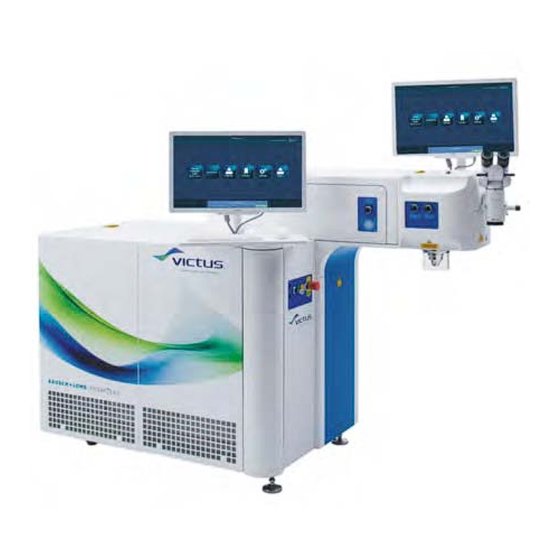
INTRODUCTION Introduction VICTUS™ Femtosecond Laser Platform The VICTUS™ Femtosecond Laser Platform is an ophthalmologic system based on femtosecond technology and is used to treat a wide variety of ophthalmologic indications. The following treatments are available: Cataract treatments The laser system is able to perform steps of a cataract treatment. -
Page 14: Use With Other Medical Devices
VICTUS™ Femtosecond Laser Platform. Technolas Perfect Vision GmbH allows only specific versions of the "LS Comfort" or the "Patient Support System S60" patient bed to be used with VICTUS™ Femtosecond Laser Platform. It must be installed by an Authorized Service Technician. For information about how to operate the patient bed refer to the user manual "Laser Patient Bed LS... -
Page 15: Definitions
INTRODUCTION femtosecond Graphical User Interface Height Zero hecto Pascal ICRS Intracorneal Ring Segments LASER Light Amplification by Stimulated Emission of Radiation LASIK Laser-Assisted In Situ Keratomileusis Liquid Crystal Display Light-Emitting Diode Lamellar Keratoplasty Laser Position Sensor LRCS Laser Refractive Cataract Surgery Laser Vision Correction Medical Electronic e.g. - Page 16 INTRODUCTION SKU: 70005780TPV * Version 6 * UM-100010770 GB 1 - 4...
-
Page 17: Safety
The VICTUS™ Femtosecond Laser Platform has been designed and constructed exclusively for the intended use described in this section. The VICTUS™ Femtosecond Laser Platform is a femtosecond laser that is used to perform cataract and refractive surgery on human eyes ( Ä... - Page 18 SAFETY Corneal abrasion or defect Pain Bleeding Inflammation Elevated intraocular pressure Incomplete procedure resulting from treatment interruption caused for example by suction loss or insufficient contact pressure Hemorrhage Decentration of planned procedure Potential complications resulting from anterior capsulotomy or lens frag‐ mentation include, but are not limited to the following: Incomplete capsulotomy or lens fragmentation In this case, the surgeon may elect to complete the procedure using tradi‐...
-
Page 19: Important Safety Considerations
SAFETY Important safety considerations Danger of injury due to user negligence! L WARNING Always double-check the following before treatment: – Are you treating the right patient? – Did you select the correct treatment? – Was the correct eye selected? – Does the entered data match the patient to be treated? Failure to verify any of the above-mentioned aspects may result in serious permanent patient injury. -
Page 20: Customer Responsibilities
Assistants have been trained by Technolas Perfect Vision GmbH staff or personnel authorized by Technolas Perfect Vision GmbH in proper handling of the system. -
Page 21: General Hazards
Users are medical providers who specialize in the diagnosis, treatment, and sur‐ gery of the eye. Users have been trained by Technolas Perfect Vision GmbH staff or personnel authorized by Technolas Perfect Vision GmbH in proper handling of the system including special precautionary measures for working with laser-emitting sys‐... -
Page 22: Electrical Hazard
SAFETY 2.7.1 Electrical hazard Life-threatening hazard due to electric shock! L DANGER There is an imminent life-threatening hazard of electric shock if live parts are touched. Damage to insulation or to specific components can pose a life- threatening hazard. – Only a qualified electrician should perform work on the electrical equip‐... -
Page 23: Laser Radiation Hazard
Safety goggles are only necessary for Authorized Service Technicians. For specifications of safety goggles the Authorized Service Technicians have to refer to field service note "FSN-1302 VICTUS, FEMTEC & EXCIMER Safety Goggles". Danger of serious injury due to incorrect operation or maintenance of the... -
Page 24: Mechanical Hazard
SAFETY Danger of fire and/or explosion due to flammable materials, solutions or L WARNING gases, or in an oxygen-enriched environment! There is a risk of fire and/or explosion when the laser output is used in the presence of flammable materials, solutions or gases, or in an oxygen- enriched environment. -
Page 25: Warning Signals And Alarms
SAFETY Warning signals and alarms Acoustic alarms Device Event Alarm frequency Laser system Running procedure Two beeps per second with a frequency of 2 kHz and a volume of 55 dB Laser chiller Critical readings for flow, One beep per second temperature, or water level Visual signals... - Page 26 SAFETY ‘Laser Stop’ button with integrated ‘Bed Stop’ Action Results To activate the ‘Laser Stop’ Any possible laser emission stops immediately by cut‐ button: ting off the laser interlock. Press the ‘Laser Stop’ The patient bed cannot be moved upwards or down‐ wards.
-
Page 27: Labeling
SAFETY Danger of injury due to system abort! L WARNING In emergency cases the user is able to abort the laser system by pressing the ‘Laser Stop’ button ( Ä on page 2 - 10). – If the system abort occurs during a treatment, –... -
Page 28: Labels In The Operating Room Entrance Area
SAFETY 2.10.1 Labels in the operating room entrance area The following labels must be displayed in the operating room entrance area: Label name Label Description No smoking Fire hazards exist from flammable or potentially explo‐ sive solid, liquid, or gaseous substances. Unauthorized Only persons authorized by the customer may enter the access prohibited... -
Page 29: Labels On The Laser System
SAFETY 2.10.2 Labels on the laser system Fig. 1: Front view Pos. Label Laser beam (small label); caution when cover is open No heavy loads Laser beam (small label); laser aperture SKU: 70005780TPV * Version 6 * UM-100010770 GB 2 - 13... - Page 30 SAFETY Fig. 2: Side view Pos. Label Laser beam (small label); laser aperture Laser beam (small label); caution when cover is open Consult operator's manual SKU: 70005780TPV * Version 6 * UM-100010770 GB 2 - 14...
- Page 31 SAFETY Fig. 3: Back view Pos. Label Laser beam (small label); caution when cover is open High voltage (power supply of the laser system) Power patient bed ‘Vacuum’ footswitch Interlock patient bed (interlock cable) ‘Procedure’ footswitch OP camera Camera live image Interlock external Laser beam (large label);...
- Page 32 SAFETY Pos. Label WEEE directive Type plate Installed software The following labels must be displayed on the laser system: Laser beam Unauthorized persons must not enter work places where laser beams are used and they are not permitted to operate laser emitting equipment. The equipment should only be operated when the user is sure that the laser output cannot damage eyes, burn skin or tissue, or result in damage to protective work...
- Page 33 SAFETY High voltage This sign warns that there are live parts with high voltage behind the cover to which the sign is attached. Unauthorized persons may not open covers that display this sign. Power Patient Bed This label shows the place of the power connection for the patient bed.
- Page 34 Technolas Perfect Vision GmbH fully complies with the WEEE Directive. This symbol on the product indicates that it must be separately collected and recycled in order to protect human health and the environment.
- Page 35 SAFETY Type plate for The type plate contains the following information: VICTUS™ Femto‐ Unit type second Laser Plat‐ Manufacturing date form with serial Year-Month-Day number £ TFW-0109 (see Serial number back side of the Supply mains laser system) Power consumption...
- Page 36 SAFETY Patent Label This patent label is located next to the type plate and refers to the website where all patents are listed under which the VICTUS™ Femtosecond Laser Platform is man‐ ufactured or used. ‘Vacuum’ foot‐ The ‘Vacuum’ footswitch is labeled with the ‘Vacuum’...
-
Page 37: Transport And Storage
The product must only be transported by a delivery company that is author‐ ized by Technolas Perfect Vision GmbH. This requirement applies to delivery, to in-house transports, and to external transports. Visual inspection after delivery The product and the required documents are given to the carrier in perfect condi‐... -
Page 38: Storage Before Installation
Technolas Perfect Vision GmbH does not assume any liability for any damage to the product arising from unauthorized unpacking. SKU: 70005780TPV * Version 6 * UM-100010770 GB... -
Page 39: Installation, Commissioning, Service, Calibration, Decomissioning And Disposal
INSTALLATION, COMMISSIONING, SERVICE, CALIBRATION, DECOMISSIONING AND DISPOSAL Installation, commissioning, service, cali‐ bration, decomissioning and disposal Installation and comissioning Initial installation and commissioning are exclusively performed by Author‐ L CAUTION ized Service Technicians. Unauthorized installation and commissioning will void the warranty. Danger of serious injury in conjunction with improper service or mainte‐... -
Page 40: Interface Of The Patient Beds "Ls Comfort" And "Patient Support System S60" By Akrus Gmbh & Co Kg
VICTUS™ Femtosecond Laser Platform Pos. Interface port Power supply (laser system) Main switch Power patient bed Fig. 4: Interface ports at the VICTUS™ ‘Vacuum’ footswitch Femtosecond Laser Platform Interlock cable ‘Interlock Patient Bed’ ‘Procedure’ footswitch OP camera (optional) Camera Live Image (optional) -
Page 41: Service And Calibration
Decommissioning and disposal must be performed by Authorized Service Technicians exclusively. Technolas Perfect Vision GmbH will arrange for the collection and recycling of (a) end-of-life Technolas Perfect Vision GmbH equipment and (b) end-of-life equip‐ ment from other manufacturers when a Technolas Perfect Vision GmbH product is purchased to replace the older equipment and has identical functionality. - Page 42 INSTALLATION, COMMISSIONING, SERVICE, CALIBRATION, DECOMISSIONING AND DISPOSAL SKU: 70005780TPV * Version 6 * UM-100010770 GB 4 - 4...
-
Page 43: Clinical Applications
CLINICAL APPLICATIONS Clinical applications The use of the laser system is the particular responsibility and is at the discretion of the user once the therapeutic benefits and possible complications and side effects have been considered. Do not exceed a total exposure duration of one hour of the eye to the LED L CAUTION ring, as ophthalmic damage could occur. -
Page 44: Patient Selection Criteria
CLINICAL APPLICATIONS Patient selection criteria Danger of injury due to the failure to observe the patient selection criteria! L WARNING Failure to observe the contraindications may result in serious permanent patient injury. – Observe the contraindications in Ä Chapter 5.2.1 ‘Contraindications’ on page 5 - 2. -
Page 45: Available Procedures
CLINICAL APPLICATIONS Patients who are blind in the fellow eye. Known sensitivity to planned concomitant medications. Patients with a recurrent or active ocular or uncontrolled eyelid disease. In addition, the following Previous corneal surgery of any kind applies to flap used in Dry eye diseases LASIK: Cataract... -
Page 46: Corneal Procedures
CLINICAL APPLICATIONS Capsulotomy With this procedure, the anterior capsulotomy is performed intraocularly by means of the laser system. The correct positioning of the capsulotomy cut on the anterior capsular surface can be verified by means of an integrated optical coher‐ ence tomography (OCT) device before starting the cutting process. - Page 47 CLINICAL APPLICATIONS This procedure allows the user to set parameters such as depth, position, and number of the entrance incision(s). Intracorneal ring segments This procedure allows to create intrastromal channel incisions for nearly all types tunnel and sizes of ring segments. The results achieved are especially convincing in the treatment of keratoconus and ectasia.
- Page 48 CLINICAL APPLICATIONS SKU: 70005780TPV * Version 6 * UM-100010770 GB 5 - 6...
-
Page 49: Hardware
Hardware Overview on the components Depending of the laser system, the position of the surgical microscope illumination in the VICTUS™ Femtosecond Laser Platform can differ as described below. VICTUS™ Femtosecond Laser Platform with surgical VICTUS™ Femtosecond Laser Platform with surgical... -
Page 50: Operating The Hardware
HARDWARE Operating the hardware 6.2.1 Main unit The main unit consists of the following components: Component Description Assistant Allows to perform the system tests, to enter and manage the patient data, to select and pro‐ workstation gram procedures, to apply vacuum for PI 125 and suction clip, to adjust the procedure according to the patient's eye and to export treatment records. -
Page 51: Assistant Workstation / Surgeon Control Screen
HARDWARE 6.2.2 Assistant workstation / surgeon control screen Assistant workstation The assistant workstation (Fig. 7) consists of a monitor, a standard keyboard and a standard mouse. The monitor is mounted on a rotating arm and can be tilted. The mouse is also used for the surgeon control screen ( Ä... -
Page 52: Start-Up Panel
HARDWARE 6.2.3 Start-up panel Fig. 9: Start-up panel Pos. Function USB ports System key-operated ‘Off’ / ‘On’ switch Indicator for the power supply ‘Laser Emission’ indicator during a running procedure. ‘Reset’ button to unlock the laser system if the ‘Laser Stop’ button has been pressed, or after a system error and also by starting the laser system. -
Page 53: Suction Status Controller
HARDWARE For initial start-up, wait at least 20 minutes to allow the cooling unit (chiller) to provide the required temperature. Press the blue ‘Reset’ button (Fig. 9/5) to start the laser source and wait for at least 20 minutes (auto‐ matic countdown). -
Page 54: Force Display
HARDWARE 6.2.5 Force display The force display (Fig. 11) is a control device that indicates important treatment parameters. Fig. 11: Force display Pos. Name Description ‘REGULAR While docking the patient's eye to the laser system with regular pressure, the PRESSURE’ LED ‘REGULAR PRESSURE’... -
Page 55: Switching The Laser Ring Light Illumination On And Off
HARDWARE 6.2.6.1 Switching the laser ring light illumination on and off Switch on the laser ring light illumination by turning the knob as follows (Fig. 12/1): Position ‘2’ : 2 LEDs are illuminated (for less reflection while centering the pupil) Intermediate positions between ‘2’... -
Page 56: Protecting The Spacer Cone
HARDWARE Depending on the configuration of your laser system, the appropriate spacer cone Ä on page 6 - 7) is installed which works only with the corresponding PI 125. "Spacer cone 9,5 + 10,5" (REF 14078) "Spacer cone V4" (REF 14540) to be to be used for the PI 125 used for the PI 125 (REF 90000145): (REF 90000115):... - Page 57 HARDWARE Surgical microscope components Fig. 14: Surgical microscope components Pos. Function Ocular lenses, adjustable Ocular distance adjustment Magnification displays Magnification adjustment (5 different magnification settings) Filter selection Tilting joint Fiber optics entry Unlocking fiber optics Surgical microscope filters Pos. Filter Filter description ‘UV’...
-
Page 58: Adjusting The Surgical Microscope Illumination
HARDWARE Pos. Filter Filter description ‘Green’ Green filter Contrast enhancement during operations on blood vessels ‘SF’ Soft filter Adaptation of LED light to halogen light; recommended for ophthal‐ mology 6.2.9.1 Adjusting the surgical microscope illumination Depending on the position of the surgical microscope illumination, adjust the illu‐ mination as described below. -
Page 59: Footswitches
HARDWARE For surgical microscope illu‐ minations that are inte‐ grated in the laser system: The illumination unit is positioned inside the laser system. It will be automatically switched on when the laser system is started. The footswitch (Fig. 18) adjusts the brightness of the surgical microscope. The left pedal of the footswitch is used to darken the picture or to switch off the surgical microscope;... -
Page 60: Patient Bed
Ensure that the power cable at the patient bed is connected to the inter‐ face port ‘Power patient bed’ at the laser system. This figure (Fig. 19) shows an example of a patient bed that can be combined with the VICTUS™ Femtosecond Laser Platform. Fig. 19: Patient bed 6.2.11.1 Referencing the patient bed If the patient bed "LS Comfort"... -
Page 61: Cleaning Instructions
HARDWARE Cleaning instructions Which cleaning agents and disinfectants to use Danger of property damage due to the use of improper cleaning agents! NOTICE The product may be damaged if it is cleaned with improper cleaning agents or scratching cleaning materials, such as cloths. –... - Page 62 HARDWARE Cleaning the spacer cone NOTICE! Contamination of the spacer cone lens occurs if alcohol enters the spacer cone! Contaminations of the spacer cone lens can only be removed by Authorized Service Technicians. – Do not spray alcohol into the spacer cone. Wipe the spacer cone with a lint-free cleaning cloth and some alcohol.
-
Page 63: Accessories And Tools
The Patient Interfaces 125 and the Suction Clips 125 are accessories and the other items are additional tools. Accessories Patient Interface 125 of the Patient Interface 125 Kit (REF 90000115) The PI 125 (REF 90000115) must only be used with the VICTUS ä Femtosecond Laser Platform (software version 2.7 and higher). -
Page 64: Tools
ACCESSORIES AND TOOLS Suction Clip 125 of the Patient Interface 125 Kit (REF 90000145) The suction clip (REF 90000145) must only be used with the VICTUS ä Femto‐ second Laser Platform (software version 3.3 and higher). The suction clip (REF 90000145) consists of a suction clip and a tube with a suc‐... - Page 65 ACCESSORIES AND TOOLS Long adapter The long adapter is used to perform the depth test. Power meter The power meter is used to perform the power test. Round plate holder The round plate holder is a holder for the adapters used to perform the pressure test and the depth test.
- Page 66 ACCESSORIES AND TOOLS Support block The support block is used during all system tests. SKU: 70005780TPV * Version 6 * UM-100010770 GB 7 - 4...
-
Page 67: Software
SOFTWARE Software Working with the software Navigation and editing of elements within the graphical user interface are identical to â a Microsoft Windows operating system. Operating the software The laser system software can be operated from either of the two locations: Assistant workstation Surgeon control screen The laser system software can be operated and managed by different personnel... - Page 68 SOFTWARE Fig. 21: Startup screen - system test is running The startup screen appears and the system self test is performed automatically. The status of the system self test is displayed in the ‘System state’ dialog box (Fig. 21). System self test performed successfully: If the system self test has been performed successfully, you can login after a few seconds (Fig.
- Page 69 SOFTWARE Fig. 24: System self test failed Click the ‘Status check’ (Fig. 24/4) button to repeat the system self test. Ensure that a USB memory stick is inserted in the USB port at the start-up panel! If the system self test fails again, click the ‘Download logs’ button (Fig.
- Page 70 SOFTWARE Pos. Button/Field Description ‘Status check’ Click to repeat the system self test. button ‘System state’ Shows the system self test results. dialog box Log in the software Fig. 25: Login screen Pos. Button/Field Description ‘user name’ field Enter your user name and your password. Click ‘Log in’ . ‘password’...
-
Page 71: Elements Of The 'Main Menu' Screen
SOFTWARE Select ‘LRCS/Therapeutics (80 kHz)’ for cataract or therapeutic treatments, or ‘Flap (160 kHz)’ for flap procedures (Fig. 26). Closing the software Precondition: The patient bed is underneath the spacer cone. Click ‘Log out’ (Fig. 27/15). Then click ‘Quit’ (Fig. 25/2). 8.1.2 Elements of the ‘Main menu’... -
Page 72: Elements Of The Treatment Screens
SOFTWARE Pos. Button/Field Description ‘Patients’ button Opens the ‘Patient selection’ screen with the ‘Patients’ and the ‘Treatments’ dialog boxes (refer to Fig. 47). ‘Licenses’ button Opens the ‘Licenses’ screen (refer to Fig. 42). ‘Settings’ button Opens the ‘Settings’ screen (refer to Fig. 40). ‘Users’... - Page 73 SOFTWARE ‘Treatment planning’ screen Fig. 28: Elements of the ‘Treatment planning’ screen (example) ‘Treatment summary’ screen Fig. 29: Elements of the ‘Treatment summary’ screen (example) SKU: 70005780TPV * Version 6 * UM-100010770 GB 8 - 7...
- Page 74 SOFTWARE ‘Regular docking treatment alignment’ screen Fig. 30: Elements of the ‘Regular docking and treatment alignment’ screen (example) ‘Treatment’ screen Fig. 31: Elements of the ‘Treatment’ screen (example) SKU: 70005780TPV * Version 6 * UM-100010770 GB 8 - 8...
- Page 75 SOFTWARE ‘Treatment result’ screen Fig. 32: Elements of the ‘Treatment result’ screen (example) Pos. Button/Field Description / Action ‘Grid:’ drop-down Select to fade in or to fade out the grid in the real-time video and have the selection choice of different grid patterns. Activates the position overlay / treatment overlay to fade in or to fade out the schematic presentation of the pupil margin or limbus margin, the planned cuts/incisions and the circular arrangement in degrees in steps of...
- Page 76 SOFTWARE Pos. Button/Field Description / Action Displays the status of the PI suction vacuum. ‘PI suction’ status indicator: ‘PI suction’ To enable or disable the PI suction, click the blue button next to the ‘PI disabled suction’ status indicator. ‘PI suction’ status indicator: ‘PI suction’...
-
Page 77: Treatment-Specific Elements
SOFTWARE 8.1.3.1 Treatment-specific elements ‘LRCS’ Fig. 33: Elements of the ‘LRCS’ ‘Treatment planning’ screen (example) Fig. 34: Elements of the ‘LRCS’ ‘Soft docking’ screen (example) SKU: 70005780TPV * Version 6 * UM-100010770 GB 8 - 11... - Page 78 SOFTWARE Fig. 35: Elements of the ‘LRCS’ ‘Treatment alignment - lens’ screen (example) Fig. 36: Elements of the ‘LRCS’ ‘Treatment alignment - cornea’ screen (example) SKU: 70005780TPV * Version 6 * UM-100010770 GB 8 - 12...
- Page 79 SOFTWARE Fig. 37: Elements of the ‘LRCS’ ‘Treatment result’ screen (example) Pos. Button/Field Description / Action Arcuate incisions in the The schematic presentation of the arcuate incisions is color-coded dis‐ video (live) image played in the real-time video. Corneal incisions in the The schematic presentation of the corneal incisions is color-coded dis‐...
- Page 80 SOFTWARE Pos. Button/Field Description / Action ‘Linear scan 0°’ OCT B Shows the real-time OCT linear scan image in 0° position of the patient's scan image eye. The flashing camera symbol represents the periodical updating of the OCT B scan image. Click the ‘Edit’...
- Page 81 SOFTWARE ‘Flap’ Fig. 38: Elements of the ‘Flap’ ‘Regular docking and treatment alignment’ screen (example) Pos. Button/Field Description OCT B scan image Shows the real-time OCT B scan image of the patient's eye. ‘Parameters’ dialog Shows flap parameters that can be changed last minute before starting the procedure.
- Page 82 SOFTWARE ‘Therapeutics’ Fig. 39: Elements of the ‘PKP’ ‘Treatment alignment’ screen (example) Pos. Button/Field Description Ring scan image Shows the real-time OCT ring scan image of the patient's eye at the diam‐ eter of the planned cut. ‘Parameters’ dialog Shows the respective therapeutic parameters that can be changed last minute before starting the procedure.
-
Page 83: Checking And Modifying Common Settings
SOFTWARE 8.1.4 Checking and modifying common settings Click the ‘Settings’ button (Fig. 27/8) in the ‘Main menu’ screen. Fig. 40: ‘Settings’ screen Manage the general settings as described in the following table. Pos. Name Description ‘Start-up mode:’ drop-down Select the treatment mode for starting up the laser system. selection You can select ‘LRCS/Therapeutics (80 kHz)’... -
Page 84: Checking Treatment Licenses
SOFTWARE 8.1.5 Checking treatment licenses Special tool: User key Insert the user key in the ‘User Key’ port (Fig. 41/1) at the start-up panel of Fig. 41: Start-up panel - ‘User Key’ port the laser system. Click the ‘Licenses’ button on the ‘Main menu’ screen (Fig. 27/7). ð... -
Page 85: User Administration
SOFTWARE User administration 8.2.1 User profiles and specific rights ‘User’ ‘Admin’ Perform system tests ( Ä Chapter 8.3 ‘System test descrip‐ tion’ on page 8 - 21) Check ‘FEMTOCLICK’ licenses ( Ä Chapter 8.1.5 ‘Checking treatment licenses’ on page 8 - 18) View patient data Add new patients ( Ä... -
Page 86: Adding Users
SOFTWARE 8.2.2 Adding users On the main screen, click the ‘Users’ button (Fig. 27/9) to open the ‘User management’ screen (Fig. 43). Fig. 43: ‘User management’ screen (example) To add a new user, click the ‘Add user’ button (Fig. 43/1). Enter the user data in the mandatory fields of the ‘Add user’... -
Page 87: Editing Registered User Accounts
SOFTWARE Click the ‘OK’ button to save the new user account. 8.2.3 Editing registered user accounts On the ‘Main menu’ screen, click the ‘Users’ button (Fig. 27/9) to open the ‘User management’ screen (Fig. 43). Click the user account that you want to edit. To edit the data, click the ‘Edit user data’... - Page 88 SOFTWARE The result of each system test is displayed in the ‘System test’ screen next to the rele‐ vant status indicator (Fig. 46). Performing the ‘System test’ How to perform these system tests is described in the Ä Chapter 9.3 ‘Performing the daily system test’...
-
Page 89: Patient / Treatment Administration
SOFTWARE After a successful system test, all status indicators have turned green. Closing the ‘System test’ Click the ‘Main menu’ button (Fig. 45/7). Patient / treatment administration Click the ‘Patients’ button (Fig. 27/6) in the ‘Main menu’ screen. Fig. 47: ‘Patient selection’ screen Manage the patients and treatments as described in the following table. -
Page 90: Adding Patients
SOFTWARE 8.4.1 Adding patients The ‘Patients’ dialog box must be opened (Fig. 47/1) in the ‘Patient selection’ screen. To add a new patient, click ‘Add patient’ (Fig. 48/3). Fig. 48: ‘Patients’ dialog box Fig. 49: ‘Add patient’ dialog box Enter the patient data ( Ä... -
Page 91: Selecting Patients
SOFTWARE Pos. Field Name Description ‘Date of birth:’ Specifies the patient's date of birth (format: MM/DD/YYYY). ‘ID:’ Specifies the patient's ID as alphanumeric string. The entry in the ‘ID:’ field must be unique! ‘OK’ button Click the ‘OK’ button to save all patient data. ‘Cancel’... -
Page 92: Editing Patient Data
SOFTWARE 8.4.3 Editing patient data Select a patient as described in Ä Chapter 8.4.2 ‘Selecting patients’ on page 8 - 25. Click the ‘Edit’ button (Fig. 48/4) to open the corresponding dialog box. Fig. 50: ‘Edit patient data’ dialog box View or edit the corresponding patient data (Fig. -
Page 93: Selecting Treatments For Execution
SOFTWARE 8.4.5 Selecting treatments for execution Precondition: A patient must be selected as described in Ä Chapter 8.4.2 ‘Selecting patients’ on page 8 - 25. To select a treatment in the ‘Treatments’ dialog box (Fig. 47/2), click on the row with the appropriate treatment. Fig. -
Page 94: Creating Treatments
SOFTWARE 8.4.6 Creating treatments Precondition: A patient must be selected as described in Ä Chapter 8.4.2 ‘Selecting patients’ on page 8 - 25. Click the ‘OD’ or ‘OS’ button (Fig. 47/3). Fig. 53: ‘Add treatment’ dialog box Select ‘Flap’ (Fig. 53/1) to create a flap procedure, ‘LRCS’ (Fig. 53/2) to create a cataract treatment or ‘Therapeutics’... - Page 95 SOFTWARE The following table describes the relevant screens for the treatment selection and the treatment planning. Pos. Name Description Fig. 54 ‘Template selection’ screen Shows information about the selected patient, the user (surgeon) and if header designated, the template's name. ‘New template’...
-
Page 96: Creating Treatments Based On Default Values
SOFTWARE 8.4.6.1 Creating treatments based on default values To create a new treatment which is based on determined parameter default values, click the ‘New template’ button (Fig. 54/2). Fig. 55: ‘Flap’ ‘Template selection’ screen (new template) ð The ‘Template selection’ screen opens (Fig. 55). Click the ‘Default’... -
Page 97: Creating Treatments Based On A Template
SOFTWARE To start the treatment, click the ‘Approve’ button (Fig. 57/11) to confirm the parameter values. To save the treatment, click the ‘Exit treatment’ button (Fig. 57). 8.4.6.2 Creating treatments based on a template Fig. 58: Treatment template (example) Select the treatment template in the ‘Template selection’ screen (Fig. 58) to create a new treatment which is based on determined parameter values for a particular patient. -
Page 98: Editing Treatments
SOFTWARE 8.4.7 Editing treatments Precondition: – A patient must be selected as described in Ä Chapter 8.4.2 ‘Selecting patients’ on page 8 - 25. Select the treatment that you want to edit Ä Chapter 8.4.5 ‘Selecting treat‐ ments for execution’ on page 8 - 27. Verify the procedure parameter values in the relevant ‘Treatment summary’... -
Page 99: Deleting Treatment Templates
SOFTWARE 8.4.9 Deleting treatment templates To delete a treatment template, click the ‘Delete template’ button (Fig. 54). Fig. 60: ‘Template selection’ screen ð All treatment templates are displayed with red highlighted frames (Fig. 60). Click the treatment template you want to delete and confirm with ‘Yes.’ 8.4.10 Treatment records A treatment record contains the following information:... -
Page 100: Procedure Parameters
ð The treatment record's data is now saved on the USB memory stick. Procedure parameters For detailed information about the relevant procedure parameter values refer to the addendum ‘VICTUS Femtosecond Laser Platform, SW V3.3 SP02 (English)’ (docu‐ ment no. ADD-100011422)! SKU: 70005780TPV * Version 6 * UM-100010770 GB... - Page 101 SOFTWARE Danger of injury due to incorrect treatment values! L WARNING All procedure parameters and values must be corrrect and appropriate for the intended treatment. The failure to verify such parameters may result in serious permanent patient injury. – Verify that the selected procedure parameters are appropriate for the selected treatment and can be applied safely.
-
Page 102: Parameters For Capsulotomy
SOFTWARE 8.5.1 Parameters for capsulotomy Precondition: A capsulotomy procedure must be selected (Fig. 62). Fig. 62: ‘Capsulotomy’ dialog box To view or specify the capsulotomy parameters, click the arrow downwards symbol (Fig. 62). Fig. 63: ‘Capsulotomy’ dialog box, opened To view or specify the optional parameters, click ‘Options’ . Fig. -
Page 103: Parameters For Lens Fragmentation
SOFTWARE Parameter dialog box Definition ‘Line spacing [µm]:’ Distance of the spots from line to line. ‘Safety distance to pupil margin [µm]:’ The safety distance defines the minimal horizontal distance from the pupil margin to the outer border of the resulting treatment zone (the most radial point of the capsulotomy pattern will have a minimal distance to the iris margin as given by the radial safety dis‐... - Page 104 SOFTWARE ‘Lens fragmentation’ dialog boxes To view or specify the circular/radial cuts, circular cuts, radial cuts or grid parameters, click the appropriate symbol ( Ä Table on page 8 - 38) to open the associated dialog box. Type Symbol Dialog box ‘Circular cuts’...
- Page 105 SOFTWARE Parameter dialog box Definition ‘Diameter [mm]:’ Diameter of the largest circle. ‘Number of radials:’ Number of radial cuts. ‘Diameter [mm]:’ Outer diameter of the radial cut. ‘Energy [µJ]:’ Energy level of each single pulse when cutting the rim. ‘Number of circles:’ Number of circular cuts.
-
Page 106: Parameters For Arcuate Incisions
SOFTWARE ‘Common options’ dialog To view or specify the common parameters, click ‘Common options’ Ä Table on page 8 - 38). Fig. 66: ‘Lens Fragmentation’ ‘Common options’ dialog box ‘Common options’ parameters Parameter dialog box Definition ‘Spot spacing [µm]:’ Distance from spot to spot on the line. ‘Line spacing [µm]:’... - Page 107 SOFTWARE ‘Incision 1’ / ‘Incision 2’ dialog box – If you change the parameters for incision 1, the relevant parameters for incision 2 are changed simultaneousely. – If you change the parameters for incision 2, it does not affect the parameters for incision 1.
- Page 108 SOFTWARE Parameter dialog box Definition ‘Resulting depth [µm]:’ ( ‘Incision 2’ ) Absolute depth of the incision 2 given in microns. ‘Position [°]:’ ( ‘Incision 1’ ) Defines the position of the first cut. ‘Position [°]:’ ( ‘Incision 2’ ) Position of the second cut, normally position angle from first cut + 180°.
-
Page 109: Parameters For Corneal Incisions
SOFTWARE 8.5.4 Parameters for corneal incisions Precondition: A corneal incisions procedure must be selected (Fig. 70). Fig. 70: ‘Corneal incisions’ parameters dialog box For general information about how to view or specify parameter values refer to Ä Chapter 8.5.1 ‘Parameters for capsulotomy’ on page 8 - 36. Parameter-specific information are described below. - Page 110 SOFTWARE Parameter dialog box Definition ‘Chord length [µm]:’ (Primary) Length of the primary corneal incision from PI 125 level to the pos‐ terior end of the primary corneal incision (measured in chord length). ‘Side port 1’ Option to perform a secondary corneal incision 1. ‘Outer width [mm]:’...
- Page 111 SOFTWARE Fig. 72: ‘Corneal incisions’ ‘Incision options: Primary incision’ parameters dialog box (example) Parameters Parameter dialog box Definition o ‘One plane’ ‘Depth [µm]:’ ( ‘Plane 1’ ) Depth of the first plane of the primary incision, secondary incision 1 or secondary incision 2. ‘Angle [°]:’...
-
Page 112: Schematic Overview On Corneal Incisions
SOFTWARE ‘Common options’ dialog Fig. 73: ‘Corneal incisions’ ‘Common options’ dialog box ‘Common options’ parameters Parameter dialog box Definition ‘Energy [µJ]:’ Energy of every single pulse creating the incision cut. ‘Spot spacing [µm]:’ Distance from spot to spot on the line. ‘Line spacing [µm]:’... - Page 113 SOFTWARE Schematic view of the plane depths Schematic view of the side cut angles SKU: 70005780TPV * Version 6 * UM-100010770 GB 8 - 47...
-
Page 114: Parameters For Flap
SOFTWARE 8.5.5 Parameters for flap Precondition: A flap procedure must be selected (Fig. 74). For general information about how to view or specify parameter values refer to Ä Chapter 8.5.1 ‘Parameters for capsulotomy’ on page 8 - 36. Parameter-specific information are described below. Fig. - Page 115 SOFTWARE ‘Rim’ dialog box Parameter dialog box Definition ‘Energy [µJ]:’ Energy level of each single pulse of the rim cut. ‘Spot spacing [µm]:’ Distance from spot to spot on the line. ‘Line spacing [µm]:’ Distance of the spots from line to line. ‘Side cut angle [°]:’...
-
Page 116: Parameters For Penetrating Keratoplasty
SOFTWARE 8.5.6 Parameters for penetrating keratoplasty Precondition: A penetrating keratoplasty procedure must be selected (Fig. 80). For general information about how to view or specify parameter values refer to Ä Chapter 8.5.1 ‘Parameters for capsulotomy’ on page 8 - 36. Parameter-specific information are described below. -
Page 117: Parameters For Lamellar Keratoplasty
SOFTWARE ‘Rim’ dialog box Parameter dialog box Definition ‘Energy [µJ]:’ Energy level of each single pulse when cutting the rim. ‘Spot spacing [µm]:’ Distance between adjacent spots on a line when cutting the rim. ‘Line spacing [µm]:’ Distance between spots of adjacent lines when cutting the rim. - Page 118 SOFTWARE ‘Size’ dialog box Parameter dialog box Definition ‘Diameter [mm]:’ Diameter of the LKP at the anterior surface of the cornea. ‘Pachymetry [µm]:’ Pachymetry of the thinnest point of the cornea at the diameter of the LKP. ‘Depth ratio [%]:’ Ratio of cutting depth to pachymetry.
-
Page 119: Parameters For Crosslinking
SOFTWARE Parameter dialog box Definition ‘Bottom bonus [µm]:’ Extension of the rim cut inside the cornea to ensure that rim and bed cut overlap. ‘Arc length [°]:’ Arc length of rim cut, normally 360°. ‘Arc center position [°]:’ Central position of rim cut in case it is not 360°. ‘Posterior diameter [mm]:’... -
Page 120: Parameters For Icrs Tunnel
SOFTWARE ‘Bed’ dialog box Parameter dialog box Definition ‘Energy [µJ]:’ Energy level of each single pulse when cutting the bed. ‘Spot spacing [µm]:’ Distance between adjacent spots on a line when cutting the bed. Fig. 89: ‘Bed’ dialog box ‘Line spacing [µm]:’ Distance between spots of adjacent lines when cutting the bed. - Page 121 SOFTWARE For general information about how to view or specify parameter values refer to Ä Chapter 8.5.1 ‘Parameters for capsulotomy’ on page 8 - 36. Parameter-specific information are described below. Fig. 91: ICRS tunnel dialog boxes - full tunnel ‘Tunnel’ ‘Incisions’...
- Page 122 SOFTWARE Parameter Definition Perform incision 1. þ ‘Position of incision 1 [°]:’ ‘Position of incision 1 [°]:’ Position incision 1. Perform incision 2. þ ‘Position of incision 2 [°]:’ ‘Position of incision 2 [°]:’ Position incision 2. ‘Length of incision 1 [µm]:’ Length of incision 1.
- Page 123 SOFTWARE Parameter Definition Perform a single tunnel segment. ‘Tunnel width [µm]:’ Width of the tunnel segment. ( ‘Tunnel 1’ ) ‘Tunnel length [°]:’ ( ‘Tunnel 1’ ) Length of the tunnel segment. ‘Position [°]:’ ( ‘Tunnel 1’ ) Central position of the tunnel segment. Fig.
- Page 124 SOFTWARE Parameter Definition Perform two tunnel segments. ‘Tunnel width [µm]:’ Width of the tunnel segment 1. ( ‘Tunnel 1’ ) ‘Tunnel length [°]:’ ( ‘Tunnel 1’ ) Length of tunnel segment 1. ‘Position [°]:’ ( ‘Tunnel 1’ ) Central position of tunnel segment 1. Fig.
-
Page 125: Schematic Overview On Icrs Tunnel Incisions
SOFTWARE 8.5.9.1 Schematic overview on ICRS tunnel incisions The ICRS tunnel procedure allows the user to select the diameter, width, and depth of the tunnel. Up to two entry incisions can be created. The incisions are radial to the tunnel. The length and position of the cuts are adjustable. A sche‐ matic view of an intrastromal tunnel dissection is shown. - Page 126 SOFTWARE Schematic side view of width and bottom bonus Overview on the incision axes for left and right eye SKU: 70005780TPV * Version 6 * UM-100010770 GB 8 - 60...
-
Page 127: Treatment
Treatment Danger of injury due to user negligence! L CAUTION The user is responsible for performing a treatment with the VICTUS™ Femto‐ second Laser Platform. The user must supervise the whole treatment process. Only the user (surgeon) is allowed to start a treatment by pressing the ‘Start’... -
Page 128: Performing The Daily System Test
TREATMENT If no further treatments will Shut down the laser system ( Ä Chapter 6.2.3.1 ‘Switching the laser system on be performed on that day and off’ on page 6 - 4). Performing the daily system test Whenever you change the treatment mode from ‘LRCS/Therapeutics (80 kHz)’ to ‘Flap (160 kHz)’... -
Page 129: Performing The Laser Position Test
TREATMENT ‘Current flow’ status ‘Supply temperature’ status ‘Current flow [l/min]’ ‘Supply temperature [°C]’ If the functionality test for the chiller has been performed successfully, the status indicators next to the parameters turn green. If an error occurs, an error message will open. In the case of an error condition, the corresponding status indicator turns red. -
Page 130: Performing The Vacuum Test
TREATMENT Click the ‘OK’ button to close the message ‘Laser position test successful.’ . ð The ‘Laser position test ’ screen closes and the status indicator turns green (Fig. 102). Fig. 102: ‘Laser position test’ suc‐ cessful 9.3.3 Performing the vacuum test Special tool: Suction reservoir If the ‘Vacuum test’... -
Page 131: Performing The Pressure Test
TREATMENT Click the ‘OK’ button to close the message ‘Vacuum test successful.’ . ð The ‘Vacuum test’ screen closes and the status indicator turns green (Fig. 104). Remove the suction reservoir dummy. Fig. 104: ‘Vacuum test’ successful 9.3.4 Performing the pressure test Special tool: Digital scale Round plate holder... -
Page 132: Performing The Power Test
TREATMENT Click the ‘OK’ button to close the message ‘Pressure test successful.’ . ð The ‘Pressure test’ screen closes and the status indicator turns green (Fig. 106). Fig. 106: ‘Pressure test’ successful 9.3.5 Performing the power test The following section describes how to perform the ‘Power test’ for cataract/thera‐ peutic and corneal treatments. -
Page 133: Performing The Depth Test
TREATMENT Click the ‘OK’ button to close the message ‘Power test successful.’ . ð The ‘Power test’ screen closes and the status indicator turns green (Fig. 108). Fig. 108: ‘Power test’ successful 9.3.6 Performing the depth test Special tool: Long adapter Round plate holder Support block Materials:... -
Page 134: Daily Routine
TREATMENT Follow the instructions in the ‘Depth test’ screen. Click the ‘OK’ button to close the message ‘Depth test successful.’ . ð The ‘Depth test’ screen closes and the status indicator turns green (Fig. 110). Fig. 110: ‘Depth test’ successful Daily routine 9.4.1 When performing a treatment... -
Page 135: Positioning The Patient On The Patient Bed
Always enter and verify all parameters very carefully. For detailed information about the relevant procedure parameter values refer to the ‘Addendum to the user manual "VICTUS Femtosecond Laser Platform, SW V3.3 SP02" (English)’ (document no. ADD-100011422)! Before starting a treatment, ensure that all parameters are within the recommended range. -
Page 136: Using A Headrest With Integrated Joystick
TREATMENT 9.4.2.1 Using a headrest with integrated joystick Fig. 111: Headrest with integrated joy‐ stick ( ‘LS Comfort’ ) Press the red pushbutton (Fig. 111/2 or Fig. 112/3) on the side of the head‐ rest and allow 3 seconds for the lock to engage and disengage to facilitate the smooth movement of the patient bed. -
Page 137: Using A Headrest With External Joysticks
9.4.3 Connecting the PI 125 to the spacer cone and positioning the suction clip The VICTUS™ Femtosecond Laser Platform may be used – with the Patient Interface 125 Kit (REF 90000115) as well as with the Patient Interface 125 Kit (REF 90000145) –... - Page 138 TREATMENT Patient Interface 125 Kit (REF 90000115) Refer to the "Patient Interface 125 Kit (REF 90000115)" instructions for use. Outer packaging Inner packaging REF 90000115 Patient Interface 125 Kit (REF 90000145) Refer to the "Patient Interface 125 Kit (REF 90000145)" instructions for use. Outer packaging Inner packaging REF 90000145...
-
Page 139: Connecting The Pi 125 (Ref 90000115) To The Spacer Cone And Positioning The Suction Clip (Ref 90000115)
TREATMENT Infection hazard due to loss of sterility! L WARNING The PI 125 Kit packaging must not be damaged or opened. The expiry dates must not be exceeded. Damaged or opened packaging may result in loss of sterility and increases the risk of infections and severe injuries. –... - Page 140 TREATMENT The following tasks shall be performed by a non-sterile person only: Fig. 115: PI 125 Kit (REF 90000115) Open the aluminium bag and remove the blister (Fig. 115/1) containing the PI 125 Kit (REF 90000115). Open the protective cover, keep all components of the kit inside the blister (Fig.
- Page 141 TREATMENT Enable the ‘PI suction’ in the software to activate the vacuum of the spacer cone. Fig. 116: ‘PI suction’ disabled Fig. 117: ‘Regular docking and treatment alignment’ screen: ‘PI suction’ enabled (example) ð The PI 125 (REF 90000115) is sucked to the spacer cone. The green ‘PI suction’...
- Page 142 TREATMENT PI recognition does not work: Fig. 118: PI recognition problems If there is a problem with the PI recognition (Fig. 118), click ‘Repeat PI recognition’ to restart the PI recognition process. If the problem persists, repeat step 4. Connect the suction reservoir to the suction port. ð...
- Page 143 TREATMENT L WARNING! Infection hazard due to loss of sterility! The following task must be performed by the sterile user only to ensure the sterility of the suction clip (REF 90000115). If the suction clip (REF 90000115) is not open, open it by pulling the snap-fit (Fig.
-
Page 144: Connecting The Pi 125 (Ref 90000145) To The Spacer Cone And Positioning The Suction Clip (Ref 90000145)
TREATMENT 9.4.3.2 Connecting the PI 125 (REF 90000145) to the spacer cone and positioning the suction clip (REF 90000145) WARNING! Ensure that the PI 125 (REF 90000145) is only used together with the suction clip (REF 90000145)! WARNING! Ensure that the suction clip (REF 90000145) is only used together with the PI 125 (REF 90000145)! The following tasks shall be performed by a non-sterile person only: Fig. - Page 145 TREATMENT Enable the ‘PI suction’ in the software to activate the vacuum of the spacer cone. Fig. 124: ‘PI suction’ disabled Fig. 125: ‘Regular docking and treatment alignment’ screen: ‘PI suction’ enabled (example) ð The PI 125 (REF 90000145) is sucked to the spacer cone. The green ‘PI suction’...
- Page 146 TREATMENT PI recognition does not work: Fig. 126: PI recognition problems If there is a problem with the PI recognition (Fig. 126), click ‘Repeat PI recognition’ to restart the PI recognition process. If the problem persists, repeat step 6. Open the protective cover of the suction clip blister pack containing the suction clip (REF 90000145) (Fig.
- Page 147 TREATMENT L WARNING! Infection hazard due to loss of sterility! The following tasks must be performed by the sterile user only to ensure the sterility of the suction clip (REF 90000145). Fig. 127: Suction clip (REF 90000145) Without touching the suction clip blister pack (Fig. 123/2), take the suction reservoir (Fig.
-
Page 148: Docking The Patient To The Spacer Cone
TREATMENT To activate the vacuum for the suction clip (REF 90000145), press the ‘Vacuum’ footswitch once. Alternatively enable the ‘Eye suction’ (Fig. 130) in the software. Fig. 130: ‘Eye suction’ disabled Fig. 131: ‘Regular docking and treatment alignment’ screen: ‘Eye suction’ enabled (example) ð... -
Page 149: For Capsulotomy And Lens Fragmentation Procedures Using A Headrest With Integrated Joystick
TREATMENT 9.4.4.1 For capsulotomy and lens fragmentation procedures using a headrest with integrated joystick Fig. 132: Patient bed control panel at the headrest ( ‘LS Comfort’ ) Move the patient bed using the joystick (Fig. 132/1 or Fig. 133/1) of the patient bed control panel at the headrest until the suction clip and the PI 125 are aligned. - Page 150 TREATMENT Check if there are air bubbles or impurities between the PI 125 and the cornea. It may be useful to change the camera focus between the lens and the cornea to better recognize air bubbles. If you see air bubbles or impurities between the PI 125 and the cornea, undock the patient.
-
Page 151: For Capsulotomy And Lens Fragmentation Procedures Using A Headrest With External Joysticks
TREATMENT 9.4.4.2 For capsulotomy and lens fragmentation procedures using a headrest with external joysticks Move the patient bed using the X/Y-joystick (Fig. 134/1) of the patient bed control panel until the suction clip and the PI 125 are aligned. Instill a maximum of six drops of balanced salt solution (BSS) in the suction clip. -
Page 152: For All Other Procedures Using A Headrest With Integrated Joystick
TREATMENT Verify that the eye is correctly centered. Verify that one of the (more central) green or yellow shear force LEDs on the force display is illuminated. If not, correct the pressure by using the X/Y-joystick (Fig. 134/1) for the shear force until one LED is illuminated green or yellow. -
Page 153: For All Other Procedures Using A Headrest With External Joysticks
TREATMENT L WARNING! Danger of injury due to contaminations! There must be no air bubbles, excess fluids, etc. between the PI 125 and the corneal surface. This situation may impair the treatment and cause severe patient injuries. Check if there are air bubbles, fluids, or impurities between the PI 125 and the cornea. -
Page 154: Repositioning The Suction Clip
TREATMENT Slowly move the patient bed upward until the PI 125 aligns completely with the corneal surface. ð The shear force display shows the lateral pressure that is exerted on the eye. The optimal position is achieved when the LEDs are illuminated green. -
Page 155: Completing A Treatment
TREATMENT Place the suction clip centrally on the patient's eye. ð The suction clip is positioned correctly. Repeat the steps in Ä Chapter 9.4.4 ‘Docking the patient to the spacer cone’ on page 9 - 22. 9.4.6 Completing a treatment Depending on the headrest being used, complete the treatment as described as fol‐... -
Page 156: Performing A Cataract Treatment
TREATMENT Performing a cataract treatment Materials: Patient Interface 125 of the Patient Interface 125 Kit (REF 90000115) or Patient Interface 125 of the Patient Interface 125 Kit (REF 90000145) Suction Clip 125 of the Patient Interface 125 Kit (REF 90000115) or Suction Clip 125 of the Patient Interface 125 Kit (REF 90000145) The following chapter describe cataract treatments using the example of a cataract... -
Page 157: Performing A Cataract Treatment Supported By A 2S-Oct
TREATMENT Verify that the ‘PI suction’ status indicator, the ‘Eye suction’ status indi‐ cator and the pressure status display are all green. Fig. 135: System parameters are verified 9.5.2 Performing a cataract treatment supported by a 2S-OCT To confirm, click the ‘Approve’ button (Fig. 135). The automatic identifica‐ tion of ocular structures is performed. - Page 158 TREATMENT If you agree with the results of the automatic identification of ocular struc‐ tures, click the ‘Confirm’ button (Fig. 136) and continue with step 23. SKU: 70005780TPV * Version 6 * UM-100010770 GB 9 - 32...
- Page 159 TREATMENT If the pupil margin has not been detected correctly or if you want to center the treatment either to the limbus or to the lens apex, proceed as follows: The following step is mandatory, because the pupil margin defines the limit for the laser cuts.
- Page 160 TREATMENT If the pupil margin is not in the right position, repeat the relevant part in step 3. Fig. 138: Limbus margin is determined (example) The purple marking circle appears in the video camera image (Fig. 138). The limbus margin is determined. If the limbus margin is not in the right position, repeat the relevant part in step 3.
- Page 161 TREATMENT If the lens body has not been detected correctly or not detected at all, the anterior lens and the posterior lens can be marked manually. To mark the anterior lens 0° position and the posterior lens 0° position, click the ‘Edit’...
- Page 162 TREATMENT Confirm with ‘Accept’ (Fig. 141). If the anterior lens 0° position and the posterior lens 0° position are not in the right position, click the ‘Edit’ button again. Mark the anterior lens 0° position and the posterior lens 0° position to find the right positions. To mark the anterior lens 90°...
- Page 163 TREATMENT If you want to accept all procedure workflow settings, click the ‘Confirm’ button (Fig. 142). The user must verify that the parameter setting has been performed correctly. Fig. 143: Pattern alignment for the cataract treatment accepted ð The color marking of the circle in the video camera image and the out‐ lines in the linear scan images turn green.
- Page 164 TREATMENT Press the ‘Start’ button to start the treatment (Fig. 143). When the green highlighted frame appears in the ‘Treatment’ screen, finally press the ‘Procedure’ footswitch. The ‘Procedure’ footswitch must be pressed from the start of the capsulotomy procedure until the end of the lens fragmentation procedure! If you release the ‘Procedure’...
- Page 165 TREATMENT Before you can continue with the arcuate incisions procedure, open the suction clip and follow the steps in Ä Chapter 9.4.4 ‘Docking the patient to the spacer cone’ on page 9 - 22 and, if required the steps in Ä...
- Page 166 TREATMENT If the parameter setting is not correct, click the ‘3-click-centration’ button (Fig. 147) and, in the video camera image, mark either the pupil margin or the limbus margin with three dots. Fig. 147: ‘LRCS’ ‘Treatment alignment - cornea’ screen ð...
- Page 167 TREATMENT To change the preset pachymetry value, click the ‘Edit’ button in the ‘AK @ 225°’ OCT B scan image (Fig. 147). Fig. 148: ‘Arcuate incision editor’ (example) L CAUTION! Be aware that the pachymetry values can vary over the length of the arcuate incisions cut.
- Page 168 TREATMENT Click the ‘Accept’ button (Fig. 149). To change the pachymetry value in the ‘AK @ 45°’ OCT B scan image, per‐ form steps 19 to 21. To start the arcuate incisions procedure, press the ‘Start’ button. When the green highlighted frame appears in the ‘Treatment’ screen, finally press the ‘Procedure’...
- Page 169 TREATMENT Click the ‘Continue’ button (Fig. 150) to open the ‘Treatment result’ screen that shows the procedure results and the number of remaining licenses. Fig. 151: ‘LRCS’ ‘Treatment result’ screen ð L CAUTION! Danger of trauma due to lowering the patient bed without having released the vacuum of the suction clip! When the vacuum is activated, lowering the patient bed leads to an abrupt loss of vacuum and causes pain to the patient.
-
Page 170: Performing A Cataract Treatment Supported By A Td-Oct
TREATMENT 9.5.3 Performing a cataract treatment supported by a TD-OCT To confirm, click the ‘Approve’ button (Fig. 135). The pupil recognition is performed. Fig. 152: ‘LRCS’ ‘Treatment alignment - lens’ screen ð The yellow marking circle appears in the video camera image (Fig. 152). The pupil margin is determined. - Page 171 TREATMENT If the pupil margin was not detected correctly or if you want to center the treatment either to the limbus or to the lens apex, proceed as follows: The following step is mandatory, because the pupil margin defines the limit for the laser cuts.
- Page 172 TREATMENT If the pupil margin is not in the right position, repeat the relevant part in step 3. Fig. 154: Limbus margin is determined (example) The purple marking circle appears in the video camera image (Fig. 154). The limbus margin is determined. If the limbus margin is not in the right position, repeat the relevant part in step 3.
- Page 173 TREATMENT Click the button next to the OCT B scan image (Fig. 153). To mark the anterior lens 0° position, mark the anterior capsule of the lens with three points. Fig. 156: Anterior lens 0° positioning is performed ð The green marking line representing the selected surface, appears in the OCT B scan image.
- Page 174 TREATMENT Click the button next to the OCT B scan image (Fig. 156). To mark the posterior lens 0° position, mark the posterior capsule of the lens with three points. Fig. 157: Posterior lens 0° positioning is performed ð The green marking line representing the selected surface, appears in the OCT B scan image.
- Page 175 TREATMENT Click the button next to the OCT B scan image (Fig. 157). To mark the anterior lens 90° position, mark the anterior capsule of the lens with three points. Fig. 158: Anterior lens 90° positioning is performed ð The green marking line representing the selected surface, appears in the OCT B scan image.
- Page 176 TREATMENT Click the button next to the OCT B scan image (Fig. 158). To mark the posterior lens 90° position, mark the posterior capsule of the lens with three points. Fig. 159: Posterior lens 90° positioning is performed ð The green marking line representing the selected surface, appears in the OCT B scan image.
-
Page 177: Performing A Corneal Treatment
TREATMENT Perform steps 10 to 29 in Ä Chapter 9.5.2 ‘Performing a cataract treatment supported by a 2S-OCT’ on page 9 - 31. Performing a corneal treatment 9.6.1 Performing a flap procedure Materials: Patient Interface 125 of the Patient Interface 125 Kit (REF 90000115) or Patient Interface 125 of the Patient Interface 125 Kit (REF 90000145) - Page 178 TREATMENT Before starting the procedure, the user must verify that the parameter values are correct. Check the parameter values for ‘Flap thickness [µm]:’ , ‘Diameter [mm]:’ , ‘Bed energy [µJ]:’ and ‘Rim energy [µJ]:’ in the ‘Parameters’ dialog box (Fig. 161), and check the position of the flap. Change it, if necessary. If you agree with the parameter setting, continue with step 7.
- Page 179 TREATMENT To agree, click the ‘Confirm’ button (Fig. 162). Fig. 163: Flap position confirmed If you have verified the parameter setting, press the ‘Start’ button (Fig. 163). When the green highlighted frame appears in the ‘Treatment’ screen, finally press the ‘Procedure’ footswitch. Remember to keep the footswitch pressed during the whole procedure.
- Page 180 TREATMENT When the flap procedure is finished, the ‘Flap’ progress bar is highlighted blue, the information footer shows the message ‘Treatment completed’ (Fig. 164), the acoustic signal stops and the green highlighted frame disap‐ pears in the ‘Treatment’ screen. Fig. 164: Flap procedure is completed Click the ‘Continue’...
-
Page 181: Performing A Therapeutic Treatment
TREATMENT Performing a therapeutic treatment Materials: Patient Interface 125 of the Patient Interface 125 Kit (REF 90000115) or Patient Interface 125 of the Patient Interface 125 Kit (REF 90000145) Suction Clip 125 of the Patient Interface 125 Kit (REF 90000115) or Suction Clip 125 of the Patient Interface 125 Kit (REF 90000145) The following chapter describes a penetrating keratoplasty procedure as an example... - Page 182 TREATMENT To confirm, click the ‘Approve’ button (Fig. 165). The OCT-supported identi‐ fication of ocular structures is performed. Fig. 166: ‘Penetrating keratoplasty (PKP)’ ‘Treatment alignment’ screen ð The yellow marking circle appears in the video camera image (Fig. 166). The pupil margin is determined. The ‘Start’...
- Page 183 TREATMENT If the parameter setting is not correct, click the ‘3-click-centration’ button and mark three points on the pupil in the video camera image. Fig. 167: Pupil margin is determined manually ð The green marking circle appears in the video camera image (Fig. 167). The pupil margin is determined.
- Page 184 TREATMENT L WARNING! Risk of tissue bridges due to movement when laser is firing! Tissue bridges may occur if vibrations from movement occur when the laser is firing. – Do not walk around while the procedure is performed. – Do not touch the patient bed or the patient's head while the procedure is performed.
- Page 185 TREATMENT When the PKP procedure is finished, the ‘Penetrating keratoplasty’ pro‐ gress bar is highlighted blue, the information footer shows the message ‘Treatment completed’ (Fig. 168), the acoustic signal stops and the green highlighted frame disappears in the ‘Treatment’ screen. Fig.
- Page 186 TREATMENT SKU: 70005780TPV * Version 6 * UM-100010770 GB 9 - 60...
-
Page 187: Troubleshooting Chart
TROUBLESHOOTING CHART Troubleshooting chart Danger of injury due to improper repair! L WARNING Improperly executed work in conjunction with troubleshooting may lead to serious injuries and significant property damage. – Perform only troubleshooting tasks that local personnel can perform according to the troubleshooting chart. –... - Page 188 TROUBLESHOOTING CHART Fault description Cause Remedy Personnel ‘Depth test’ failed. The depth test has failed Authorized Try to perform the depth test after selecting another diam‐ Service Tech‐ again. eter in the ‘Diameter:’ drop‐ nician If the ‘Depth test’ fails repeat‐ down field.
- Page 189 TROUBLESHOOTING CHART Fault Cause Remedy Personnel description Ask the patient to leave the patient bed very carefully. Solve the problem, if possible. Otherwise call an Authorized Service Technician, if necessary Emergency Emergency shut‐ Authorized If an emergency shutdown occurs during a treatment, make shutdown in down has been sure that the eye suction is automatically switched off.
- Page 190 TROUBLESHOOTING CHART Surgical microscope Fault description Cause Remedy Personnel ¾ Lighting defect Contact an Authorized Service Authorized Service Technician Technician. Magnification defect ¾ Authorized Service Contact an Authorized Service Technician. Technician Image through the surgical Focus of oculars is Adjust focus of the oculars. Assistant microscope is blurred.
-
Page 191: Technical Data
TECHNICAL DATA Technical data 11.1 General specifications Fig. 169: Dimensions of the laser system (top view) with patient bed "LS Comfort" SKU: 70005780TPV * Version 6 * UM-100010770 GB 11 - 1... - Page 192 TECHNICAL DATA Fig. 170: Dimensions of the laser system (top view) with patient bed "Patient Support System S60" Fig. 171: Dimensions of the laser system (side view) SKU: 70005780TPV * Version 6 * UM-100010770 GB 11 - 2...
-
Page 193: Operating Conditions
TECHNICAL DATA Data Value Unit Weight (without patient bed) 640 - 690 kg depending on configuration Length (without patient bed) 208 cm Length (with patient bed) 210 cm Width (without patient bed) 83 cm Height 168 cm 11.2 Operating conditions Ambient operating condi‐... -
Page 194: Laser Specifications
Beam divergence 15 ° Essential performance Energy and pulse positioning are considered as an essential performance of the VICTUS™ Femtosecond Laser Platform. 11.4 Transport and storage conditions Store the laser system in a dry and dust-free location. Protect the laser system from direct sunlight. -
Page 195: Index
Assistant workstation............6 - 3 overview................. 6 - 1 Authorized Service Technician........2 - 4 Cone..................6 - 7 Authorized Technolas Representative....... 2 - 4 Cone protection..............6 - 8 Contraindications Brands..................A - 3 arcuate incisions............5 - 3 capsulotomy.............. - Page 196 INDEX Corneal treatment performing..............9 - 51 Faults................... 10 - 1 Creating Flap treatments..............8 - 28 contraindications............5 - 3 Creating treatments description..............5 - 4 based on default values......... 8 - 30 parameters..............8 - 48 based on templates..........8 - 31 Flap procedure Crosslinking performing..............
- Page 197 INDEX Laser specifications............11 - 4 Laser system Parameters interface description..........4 - 2 arcuate incisions............8 - 40 switching off..............6 - 5 capsulotomy.............. 8 - 36 switching on..............6 - 4 corneal incisions............8 - 43 Lens fragmentation crosslinking..............
- Page 198 INDEX ICRS tunnel, creating..........8 - 28 Settings................8 - 17 lamellar keratoplasty, creating......8 - 28 checking..............8 - 17 lens fragmentation, creating........ 8 - 28 modifying..............8 - 17 penetrating keratoplasty, creating....8 - 28 Shifting the camera focus..........6 - 7 Procedures Side effects................
- Page 199 INDEX Symbols corneal, creating............8 - 28 in the entrance area..........2 - 12 corneal, performing..........9 - 51 in this user manual............. A - 1 corneal incisions, performing......9 - 30 on the laser system..........2 - 13 crosslinking, performing........9 - 55 System self test flap, performing............
- Page 200 10 - 3 description..............6 - 5 surgeon control screen.......... 10 - 3 Vacuum test................. 9 - 4 surgical microscope..........10 - 4 VICTUS Femtosecond Laser Platform user key................ 10 - 4 overview................. 1 - 1 Viewing Use..................2 - 1 treatment records............
-
Page 201: Appendix
Appendix SKU: 70005780TPV * Version 6 * UM-100010770 GB 13 - 1... - Page 202 APPENDIX Table of contents EMC declaration SKU: 70005780TPV * Version 6 * UM-100010770 GB 13 - 2...
- Page 203 EMC declaration Guidance and Manufacturer’s Declaration – Electromagnetic Emissions The VICTUS™ Femtosecond Laser Platform is intended for use in the electro‐ magnetic environment specified below. The customer or user of the VICTUS™ Femtosecond Laser Platform should assure that it is used in such an environment.
- Page 204 APPENDIX Guidance and Manufacturer’s Declaration – Electromagnetic Immunity The VICTUS™ Femtosecond Laser Platform is intended for use in the electro‐ magnetic environment specified below. The customer or user of the VICTUS™ Femtosecond Laser Platform should assure that it is used in such an environment.
- Page 205 APPENDIX Guidance and Manufacturer’s Declaration – Electromagnetic Immunity The VICTUS™ Femtosecond Laser Platform is intended for use in the electro‐ magnetic environment specified below. The customer or user of the VICTUS™ Femtosecond Laser Platform should assure that it is used in such an environment.
- Page 206 If the measured field strength in the location in which the VICTUS™ Femtosecond Laser Platform is used exceeds the applicable RF compliance level above, the VICTUS™ Femtosecond Laser Platform should be monitored to verify normal operation. If abnormal performance is observed, additional measures may be necessary, for instance re-orienting or relocating the VICTUS™...
- Page 207 APPENDIX Rated maximum output Separation distance according to frequency of transmitter meters (m) power of transmitter (W) For transmitters rated at a maximum output power not listed above, the recommended separation distance d in meters (m) can be estimated using the equation applicable to the frequency of the transmitter, where P is the maximum output power rating of the transmitter in watts (W) according to the transmitter manufacturer.
Need help?
Do you have a question about the Victus and is the answer not in the manual?
Questions and answers