Advertisement
Quick Links
Advertisement

Subscribe to Our Youtube Channel
Summary of Contents for SCHLAPPI ENGINEERING Angle Grinder
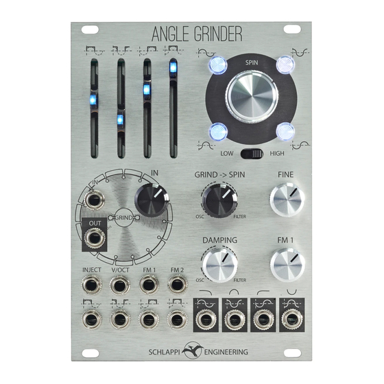
- Page 1 SCHLAPPI ENGINEERING...
-
Page 2: Specifications
SPECIFICATIONS SCHLAPPI ENGINEERING •Quadrature Sine Wave VCO / State Variable Filter -with four phase related outputs: 0°, 90°, 180°, 270° -or lter response outputs: LOW PASS, BAND PASS, HIGH PASS, INVERTED BAND PASS •HIGH range from 10Hz to over 20kHz •LOW range from 0.3Hz to over 600Hz •Sine wave outputs are 5Vpp (+-2.5V ) •Grind section is a voltage controlled waveshaping section... - Page 3 SCHLAPPI ENGINEERING Angle Grinder is a quadrature sine wave oscillator, lter, and waveshaping e ect. The SPIN section is a quadrature sine wave oscillator. The GRIND section compares each phase against input signal, then subtracts the result from the input signal.
-
Page 4: How It Works
HOW IT WORKS V/OCT SPIN FINE (COARSE) GRIND -> SPIN FREQUENCY INPUTS (FILTER IN) (mixer) SPIN AUDIO square waves are subtracted INPUTS from input signal (OSC/FILTER CORE) INJECT MODE OUTPUTS DAMPING INVERTED LOW PASS BAND PASS HIGH PASS BAND PASS FILTER GRIND 0º... - Page 5 SPIN -With GRIND->SPIN and DAMPING fully CCW 0° the four SPIN outputs will have phase-related sine waves -These all come from the same oscillator and will be at the same frequency -This will track v/oct (check that FM1 is down) -At audio rate you can process them seperately to create stereo e ects or mix them together -At LFO rate you could use them for quad panning...
- Page 6 GRIND - OSCILLATE -With GRIND->SPIN and DAMPING fully CCW GRIND OUT -With nothing plugged into the input* NO SLIDERS UP -Turn GRIND IN clockwise to feed the SPIN section into the GRIND section -Try listening to the GRIND OUT and exploring the sliders one at a time -The 90°...
- Page 7 GRIND - OSCILLATE -Same patch as previous page but raising more than one slider at a time GRIND OUT NO SLIDERS UP -Notice how the “one slider up” waveform is di erent than the one on the previous page? -This is because these shots were taken at a di erent frequency -As more sliders are brought up we converge on a pyramidal shape...
-
Page 8: Knob Positions
GRIND - EXTERNAL -With the SPIN section oscillating in LFO mode plug in an external wave form and listen from the GRIND out -The waveforms to the right show a triangle input in yellow and GRIND out in blue -Each phase of the internal oscillator is compared against and subtracted from an external signal -If the internal oscillator is at a low frequency the output with resemble a supersaw... - Page 9 FILTER -With a external signal in the INPUT and the GRIND->SPIN knob turned CW the external signal will disrupt the oscillations -The outputs will become LOW PASS, BAND PASS, HIGH PASS, and INV BAND PASS -GRIND sliders are now voltage controlled non-linear feedback paths Experiment with all controls -Four outputs responding to a triangle...
- Page 10 INJECT -The INJECT jack bypasses the GRIND section as a direct input to the oscillator/ lter core -It is header selectable to be DC or AC coupled on the read of the module -AC is selected by default -The AC mode is a high pass set to turn an incoming signal (square or saw preferably) into spikes to reset the oscillator -This can act as a soft sync...
Need help?
Do you have a question about the Angle Grinder and is the answer not in the manual?
Questions and answers