Table of Contents
Advertisement
Quick Links
Advertisement
Table of Contents

Summary of Contents for RCS SM1020
- Page 1 Product Guide GP Gateway SM1020 GP Gateway SM1020/W GP Gateway Product Guide | Issue 1.5 | The SM1020 GP Gateway/s Page 1 Product Guide | Issue 1.5 | The SM1020 GP Gateway/s Page 1 Product Guide | Issue 1.5 | GP Gateway Page 1 Product Guide | Issue 1.5 | The SM1020 GP Gateway/s...
-
Page 2: Table Of Contents
Introduction The GP Gateway Contents INTRODUCTION 1.1 The SM1020 GP Gateway Range 1.2 Configuration 1.3 LED Status Information SETTING UP THE GATEWAY 2.1 User Instructions 2.2 Screen Shot of the Configuration Page 3. CONFIGURATION 3.1 Units 3.2 Network Parameters 3.3 XML Parameters 3.4 Adaptor Control... -
Page 3: Introduction
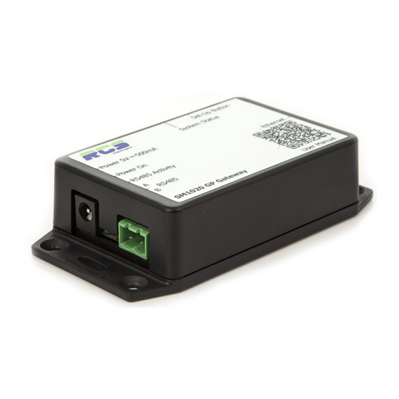
The GP Gateway Introduction The SM1020 GP Gateway Range The RCS GP gateway has been designed as a cost effective solution to allow Bi-directional RS485 communications with RCS control products to and from IP based monitoring bureaus and other 3 party systems. -
Page 4: Led Status Information
LED Status The GP Gateway LED Status Information Power LED (Green) – This indicator will be illuminated constantly when the 5vdc power supply is present. RS485 Status LED (Red) – This indicator will initially be off, until valid communication activity is detected. Once RS485 communication activity is present the LED will flash at an intermittent rate. -
Page 5: Setting Up The Gateway
Setting up the Gateway The GP Gateway 2 Setting up the Gateway User Instructions The GP Gateway has a default IP address of 192.168.0.101. The user can ensure that this address is loaded by pressing the setup button on the side of the GP Gateway on power up for 5 seconds. Please follow the procedure listed below to be presented with the GP Gateway configuration page. -
Page 6: Configuration
Please note the controller address should be entered in exactly the same format that it appears on the controller. The SM1020/W variant also allows the user to enter three characters of text preceding the unit number e.g JSR1.0. - where JSR stands for J.Sainsbury Restaurant. This text will be included within the XML string that is supplied to the monitoring bureau, and can aid in the physical location of a particular device. -
Page 7: Specification
Specification The GP Gateway 4 Specification Ethernet Interface: 10/100 Base-T. External Power supply: (Supplied) AC 240v 50/60Hz <0.2A DC 5V ± 5% <0.5A EMC: EN 55014-1:2006 A2 Weight: 65 Grams (Excluding PSU) Size: 110mm (L) x 57mm (W) x 26mm (D) – Inclusive of mounting flanges. -
Page 8: Ordering Information
Ordering Information The GP Gateway Ordering Information Part Number Product Name Description SM1020 GP Gateway General Purpose RS485 to IP Protocol Converter SM1020/W GP Gateway for use with General Purpose ModBus to IP Protocol Converter for Williams refrigeration units Williams / LAE controllers Product Guide | Issue 1.5 | GP Gateway... -
Page 9: Revision History
Revisions The GP Gateway 5 Revision History Revision Date Author Amendments Comments First Draft 02/02/2013 First Draft Issued for internal review Issue 1.0 17/06/2013 Agreed content/format Issued for customer distribution Issue 1.1 28/06/2013 Image alteration Issued for customer distribution Issue 1.2 Issue 1.2 16/01/2014 16/01/2014... -
Page 10: Disclaimer
To allow for design and specification improvements, the information contained within this document is subject to change at any time without prior notice. RCS Energy Management shall not be liable for any errors or omissions, for incidental or consequential damages either directly or indirectly resulting from the misuse of this product or associated document. -
Page 11: Contact Details
Berkshire RG14 5SJ UNITED KINGDOM Tel: +44 (0) 1635 231600 Fax: +44 (0) 1635 231699 Email: sales@rcsenergymanagement.co.uk Website: www.rcsenergymanagement.co.uk RCS Energy Management is a trading name of Maxey Moverley Ltd. Product Guide | Issue 1.5 | GP Gateway Page 11... -
Page 12: Appendices
EMI and received EMI. RCS suggest the use of Belden type cable (or similar) such as 9501 / 2, with a characteristic impedance of 120 ohms. The RCS SM1020 gateway devices have termination resistors incorporated, however an end of line terminator (120 Ohms) is recommended to be fitted on the last device on a zone.
Need help?
Do you have a question about the SM1020 and is the answer not in the manual?
Questions and answers