Table of Contents
Advertisement
Quick Links
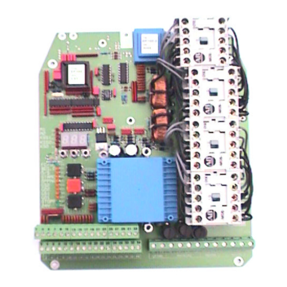
Automatic Control Panel, Type EP102
For electrically operated gates, barriers & doors
EP102-1 For control of one motor.
EP102-2 For control of two motors
User Manual
Version 1.03
Edition 1
Box 125,
S-284 22 Perstorp
Sweden
Phone: +46 (0)435 77 95 00
Fax: +46 (0)435 77 95 29
E-mail: daab@daab-port.se
Advertisement
Table of Contents

Summary of Contents for DAAB EP102
- Page 1 Automatic Control Panel, Type EP102 For electrically operated gates, barriers & doors EP102-1 For control of one motor. EP102-2 For control of two motors User Manual Version 1.03 Edition 1 Box 125, S-284 22 Perstorp Sweden Phone: +46 (0)435 77 95 00 Fax: +46 (0)435 77 95 29 E-mail: daab@daab-port.se...
-
Page 2: Table Of Contents
Draught exclusion in a building with two doors................18 Entrance with barrier and gate operating together..............18 Commissioning, inter lock function.................... 19 Blocking functions explanation....................20 Channel list for EP102........................ 21 Service fault-finding........................24 Error messages ........................25 Notes............................26... -
Page 3: General Specification
General Specification The EP102 control panel has been designed with great care to control the entry and exit of vehicles and personnel, through gates, shutters, doors and rising arm barriers. It provides a multi-purpose interface, evaluating signals from the Access control equipment, limit switches and safety equipment, to give the customer a vast range of programmable options, which are fully explained herein. -
Page 4: Technical Specification
Supply voltage, single phase 1x230VAC (±10%) Fuse max T10A. Frequency 50Hz Motor EP102-1 for single drive motor, EP102-2 for two drive motors. Motor, three-phase operation three-phase induction motor, 0.18-0.55kW. Motor, single-phase operation single-phase motor with operating condenser 0.18-0.25kW. Fuses Internal fuse =T4A, external fuse required = T10A. -
Page 5: Connection Instructions
Connection instructions Power Supply connection For the EP102 control panel to be electrically safe, function correctly and comply with current regulations, it is important that it is assembled and connected correctly. NB: The circuit board must be earthed via the mounting plate. -
Page 6: Low Voltage Connection
• Do not connect anything in the safety circuit, e.g. relays or lamps, that may interfere with the Safety circuit. If an intermediate relay must be used to obtain open and closed signals, DAAB Should be contacted for instructions. Safety buffers, stop and limit switches are considered part of the safety circuit. - Page 7 Photocell/loop, stops gate when closing. Contact normally closed, when powered. Earth connection. Communication Name Term. Function RS485 31,32 Communication with a separate DAAB panel. 24V DC output Name Term. Function +24V DC 24V DC for supply to additional access controls Earth termination.
-
Page 8: Siphon Or Interlock Between Two Gates Or Between A Gate And A Barrier
There is a built in safety buffer monitor on the board which functions with both mobile and static safety buffers. The EP102 monitors itself by an autotest, which takes place before each start and after every stop. An error message is received if there is a fault. A 2.0KΩ resistor must be installed in the safety buffer circuit. -
Page 9: Commissioning
EP102-2 is a control panel for 2 motor systems. EP102-1 is a control panel for 1 motor system. The information in the specification about gate half 2 or motor 2 does not apply to EP102-1. 6. The specifications are the same for different types of applications: Gates with safety buffers. - Page 10 Display Diodes To make matters easier when commissioning and fault-finding, light diodes are provided to indicate faults and input signals. Red light diodes for error indication Unlit diode means no error. Lit diode means error. Flashing light diode means previous error, diode goes off next time gate is operated.
-
Page 11: Reading And Setting Values
Note all settings Note all the settings written during commissioning in the channel list under value set (section on channel list for EP102). It is best to use a pencil so that values can be changed. -
Page 12: Safety Circuit
2. Step using the + key or the – key until C39 appears (Open time delay). 3. Press the ↵ key. The number appears in the display. 4. Read off the value, which for the DAAB magnetic lock should be 0.5 sec. 5. Correct delay not displayed? Set correct time as in items 6-8. -
Page 13: Direction Of Rotation
If a value higher than 0.80 needs to be set there is presumably something wrong. Contact DAAB for advice. The type of supply feeding the control panel must be set if the load sensor is to function. -
Page 14: Motor Protection (C44 & C45)
Setting of limit for load sensor (C30,C31) 1. Press the ↵ key so that the display shows the channel number (C to extreme left). 2. Step using the + key or the – key until C30 appears (load limit, motor 1). 3. -
Page 15: Latched/Deadman Control
Latched control may be set in either direction. • EP102 is supplied ready for deadman control. Before latched control is set, the gate must be fitted with safety buffers and the load sensor adjusted. This function must be checked. -
Page 16: Automatic Closure
Automatic closure In order to avoid the gate remaining open, you can choose to make it close after a preset time, which ranges from 1 second to 9 min 59 sec. The time begins running when the gate stops moving. If the Open or Close push-buttons are pressed, the time is reset to zero and begins running again. -
Page 17: Programmable Input 1- Partial Opening Input
When the input is set for gate leaf 2 opening, the input signal always results in opening gate leaf 2. Inter lock function (C62=3) EP102 sends an opening signal to another EP102, for inter lock opening. Communication cable is required. -
Page 18: Inter Lock Function
Inter lock function Two or more EP102 panels can communicate with each other and send interlocks and start signals between the gates. Attention • Commissioning and function tests for each gate shall be carried out according to section “Commissioning”, before the parameters are set between the gates. -
Page 19: Commissioning, Inter Lock Function
Commissioning, inter lock function Communication C95 In order to have communication between two EP102 panels, C95 should be set to the appropriate values.. On the first panel C95 is set to 1 and on the second C95 is set to 2. -
Page 20: Blocking Functions Explanation
Blocking functions explanation. Blocking between 2 doors (C64) If blocking is set communication between the control panels must work. If not it is not possible manoeuvre the doors. In the table the word “door” is used. This can of course be replaced with gate or barrier. Set ups and combinations Door Door... -
Page 21: Channel List For Ep102
Channel list for EP102 The channel list is the same for control type EP102-1 (1 motor) and control type EP102-2 (2 motors). Certain channels apply only to control type EP102-2. These are marked by an * before the channel number. - Page 22 Number of safety buffers, load sensor function and motor protection Specification Value Start C40 Number of safety buffers connected to KSS1, 0=buffer off C41 Number of safety buffers connected to KSS2, 0=buffer off. C42 Number of safety buffers connected to KSÖ, 0=buffer off. C43 Load sensor may be changed only for service and fault-finding.
- Page 23 Displays for supplementary card DB307 Specification Value Start C70 Supplementary card 0=none 1=DB307 0=channel 71-82 not shown 1=channel 71-82 shown and can be set Time delays Description Value Start C90 Time for blocking of load sensor at start 0.01-0.99 sec 0.60 C91 Time for motor protector 0.01-0.99 sec...
-
Page 24: Service Fault-Finding
↓ ↓ If all displays light as they should, no error messages are displayed and the automatic controls still fail to start, note the item number (on front page of manual). Contact DAAB for help. -
Page 25: Error Messages
Error messages E01=Motor protector motor 1 tripped out. E02=Motor protector motor 2 tripped out. Possible reasons: Motor running sluggishly or seized, disengage to test. Blown fuse Phase error. Break in cable to motor, or in motor winding. Is correct limit for motor protector set? (C44,C45). E03=Max. -
Page 26: Notes
Stands for “Öppna/Stäng” - Open/Close Accessories DAAB Portteknik have several accessories for different applications for gate- barrier- door manoeuvring. Below is a selection and a short description. Please contact DAAB for further information. Product Function Output card To achieve movement indication, position indication, controlling (Mounted on EP 102 traffic light, alarm output, the outputs are programmable.
Need help?
Do you have a question about the EP102 and is the answer not in the manual?
Questions and answers