
Related Manuals for Bigdog Mower Co. ALPHA MPX


Summary of Contents for Bigdog Mower Co. ALPHA MPX
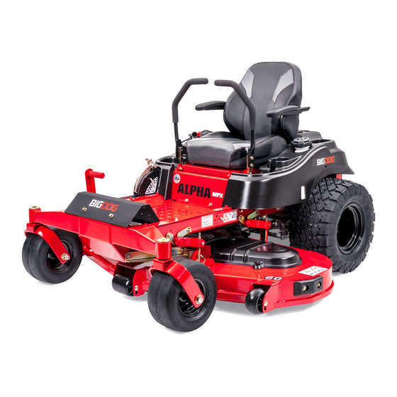
- Page 1 BIGDOG MOWER CO. ALPHA ® ® General Service Manual 200 South Ridge Road Hesston, Kansas 67062 125277 REV A...
- Page 2 WARNING The engine exhaust from this product contains chemicals known to the state of California to cause cancer, birth defects or other reproductive harm. NOTICE OF REQUIREMENT OF SPARK ARRESTER MUFFLER This equipment may create sparks that can start fires around dry vegetation. California Public Resources Code Section 4442.6 provides that it is unlawful to use or operate an internal combustion engine on any forest-covered, brush-covered, or grass-covered land unless the engine is equipped with a spark arrester maintained in effective working order.
-
Page 3: Table Of Contents
Table of Contents General Information ..........1-1 ®... - Page 4 Electrical ............7-1 Maintenance .
-
Page 5: General Information
GENERAL INFORMATION Clear away heavy build-up of grease, oil and dirt, especially ® BigDog Service Program in the engine compartment and under the seat platform areas; minute dust particles are abrasive to close-tolerance This manual is part of a service package for the BigDog ®... - Page 6 REV A 125277...
-
Page 7: Safety
SAFETY • Do not remove fuel cap or fill tank with engine running or while engine is hot. Clean up any fuel spills. • Allow engine to cool before storing machine inside a building. This safety alert symbol is used to call attention to a •... -
Page 8: Operation Precautions
Understand Machine Operation Never leave machine unattended with ignition key in switch, especially with children present. Only qualified and trained personnel should operate Follow daily and weekly checklists, making sure hoses the equipment. are tightly secured and bolts are tightened. ... -
Page 9: Maintenance Precautions
Use a stick or similar instrument to clean under the Never check fuel level with an open flame. mower making sure that no part of the body, especially Never use an open flame to look for leaks anywhere on arms and hands are under mower. - Page 10 Shorts caused by battery terminals or metal tools Avoid the hazard by: touching metal mower components can cause sparks. • Filling batteries in a well-ventilated area. Sparks can cause a battery gas explosion which will • Wearing eye protection and rubber gloves. result in personal injury.
-
Page 11: Torque
TORQUE Standard Torques The following chart lists the standard torque values for the threaded fasteners found in this manual. Torque all cap screws, nuts and set screws to these values unless a different torque is shown in the Special Torques section. Size ft-lbs N•m... - Page 12 REV A 125277...
-
Page 13: Power Unit Maintenance
POWER UNIT MAINTENANCE Steering Adjustments Keep hands, hair, clothing, etc., clear of the pulleys Steering control lever neutral adjustment on top of the transmissions. Exercise extreme The mower’s steering has been factory adjusted to caution. eliminate creeping when the steering control levers are in the neutral position. - Page 14 5. Loosen the nuts adjacent to the steering bushing. 9. The steering control levers should be adjusted so that Figure 4-2 they align vertically with each other (± .125") when in the neutral position (Figure 4-4). The space between the ends of the steering control handles should be .50"...
- Page 15 8. To check, move the steering control lever to the Control lever stops adjustment reverse position and release. The steering control lever should return to the neutral position. If not, repeat steps 1 through 7. Keep hands, hair, clothing, etc., clear of the rotating drive wheels/hubs during this process.
-
Page 16: Park Brake Spring Adjustment
10. Lower the seat platform and secure in place. Never operate the mower with a non-functioning seat switch. Always reconnect the seat switch to the mower harness. A. Female spades C. Mower harness B. Seat switch Figure 4-8 A. Cap screws B. -
Page 17: Transaxle Drive Belt
5. Close seat platform and re-install seat platform NOTE: Inspect the belt every month and replace as hardware. needed. Replace the belt every two (2) years. If the transaxle belt fails, loss of control will occur especially when operating on a slope. If you lose steering control while operating the machine, place the steering control levers in the park brake position immediately. - Page 18 8. Remove the transaxle drive belt from the transaxle 2. Lower the deck to the lowest setting. drive pulleys and the engine pulley. Figure 4-13, & Figure 4-14 Top view with engine removed Allow the engine and muffler to cool before proceeding with the following procedure.
-
Page 19: Hydraulic System
Use SAE 20W50 motor oil, 15W50 synthetic oil or 20W50 Top view with engine removed synthetic oil when changing the system oil and filter. The hydraulic expansion tank is located in front of the engine and under the operator’s platform. Figure 4-16 Check oil level in hydraulic system after every 40 hours of operation or weekly, whichever occurs first. - Page 20 3. Place an oil drain pan beneath the oil filter and remove the oil filter from the transaxle. 4. After the oil has been drained, wipe the filter base surface off and apply a film of new oil to the gasket of the new replacement filter.
- Page 21 IMPORTANT: Purging procedures must be followed after 1. Raise the rear of the mower and block with certified changing the oil and filter. Refer to Purging Procedure section jack stands. The rear wheels need to be able to rotate for detailed information. freely and clear of all obstructions.
-
Page 22: Tires
Tires 7. It may be necessary to repeat Steps 5 and 6 until all the air is completely purged from the system. When the transaxle operates at normal noise levels and It is important for level mowing that the tires have the moves smoothly forward and reverse at normal same amount of air pressure. -
Page 23: Engine Maintenance
ENGINE MAINTENANCE General Engine Maintenance IMPORTANT: All oil drips or spills must be cleaned off of the engine plate, muffler, and exhaust system before operating the machine. Detailed instructions and recommendations for break-in and regular maintenance are specified in the Engine Owner’s 8. -
Page 24: Fuel Evaporation System Filter
Fuel Evaporation System Filter The vapor lines are connected to the fuel tank as shown. They connect the fuel tank to the engine’s vapor port. Figure 5-5 These mowers have a fuel evaporation system filter. This filter must be checked and replaced every 100 hours or annually whichever comes first. - Page 25 Engine RPM Settings The engine rpm’s are set at the factory for maximum mowing efficiency. Occasionally it may be necessary to check and adjust the settings. The idle speeds should be set as follows: KAWASAKI FR691V / FR730V ENGINE SPEED MODEL NO.
- Page 26 REV A 125277...
-
Page 27: Deck Adjustments
DECK ADJUSTMENTS Deck Leveling 1. Park the mower on a hard, flat surface. 2. Check tire pressures (8–12 psi) to make certain the tires are properly inflated before starting to level deck. Stop engine. Make sure deck clutch switch is in the down (OFF) position. - Page 28 Replace any blade which is bent, cracked or broken. Lay the blade on a flat surface and check for distortion (Figure 6-5 & Figure 6-6). Replace any distorted blade. Never attempt to straighten a bent blade by heating, or weld a cracked or broken blade as the blade may break and cause serious injury.
- Page 29 3. Install a blade lock tool (Excel part number 381442) End view of blades, comparing twisted and straightened blades. over the two blades to prevent them from rotating. Figure 6-7 Repairs or maintenance requiring engine power should be performed by trained maintenance personnel only.
-
Page 30: Deck Belt
5. Inspect the blade for damage. If the blade is damaged, • separation replace it. If the blade is not damaged, either sharpen • weather checking it or replace it with a new blade or another sharpened • cracking used blade. •... - Page 31 6. Remove the deck drive belt from the electric clutch pulley located on the engine shaft. Figure 6-9 48"/54"/60" Decks A. Deck drive belt B. Electric clutch pulley A. Deck cover C. Spring mount B. Idler spring Figure 6-9 Figure 6-8 7.
- Page 32 The following notes are the same for the different deck sizes. 1. There is no tension adjustment of this belt. 2. Route belt as shown. Deck Belt Routing Figure 6-10 REV A 125277...
- Page 33 ELECTRICAL Electrical Schematics 125277 REV A...
- Page 34 Light Harness Schematic LIGHT, RH HARNESS HOUR METER LIGHT, LH REV A 125277...
- Page 35 MAINTENANCE Maintenance Schedule Refer to Figure 8-1, Figure 8-2, & Figure 8-3 WEEKLY * ANNUALLY SERVICE AT OR 40 OR 100 INTERVALS INDICATED HOURS HOURS Verify safety start interlock system Prior to each use Visually inspect unit for loose hardware and/or damaged parts Prior to each use Visually inspect tires Prior to each use...
- Page 36 Maintenance Locator Chart Figure 8-1 1. Engine Oil Fill & Dipstick 2. Fuel Filter 3. Engine Air Cleaner 4. Engine Oil Drain Valve 5. Battery 6. Fuel Tank 7. Engine Oil Filter 8. Park Brake Switch (2) 9. Drive Tire 10.
- Page 37 TROUBLESHOOTING SUGGESTED SYMPTOMS PROBABLE CAUSES REMEDIES SUGGESTED SYMPTOMS PROBABLE CAUSES REMEDIES Mower creeps when Steering linkage needs Adjust linkage steering control levers are adjustment Starting motor does not Steering control levers not Place steering control in neutral crank in park brake position or levers in park brake posi- switch not adjusted tion or re-adjust switch...
- Page 38 REV A 125277...
- Page 39 INDEX PAGE PAGE Avoid Acid Burns .............2-4 Maintenance Locator Chart ........8-2 Avoid Fire Hazards ..........2-2 Maintenance Precautions ........2-3 Belt Adjustment ............4-5 Mower Blade Maintenance ........6-1 Belt Replacement ............4-5 Mower Blade Replacement ........6-3 Blades ..............6-1 Operate Machine Safely ........2-2 Control Lever Stops Adjustment ......4-3 Operation Precautions ...........
- Page 40 PAGE PAGE REV A 125277...
Need help?
Do you have a question about the ALPHA MPX and is the answer not in the manual?
Questions and answers
Drive belt size on big dog alpha mp model#939934. s/n 20095116