Table of Contents
Advertisement
Advertisement
Table of Contents

Summary of Contents for Vectronic Aerospace VERTEX Plus Collar
- Page 1 VERTEX Plus Collar User Manual Version: 1.3 Last Change: 19.03.2019...
- Page 2 VERTEX Plus Collar User Manual © 2017 VECTRONIC Aerospace GmbH All rights reserved. No parts of this work may be reproduced in any form or by any means - graphic, electronic, or mechanical, including photocopying, recording, taping, or information storage and retrieval systems - without the written permission of the publisher.
- Page 3 Document Change Record...
-
Page 4: Table Of Contents
Contents Table of Contents .......................8 Product overview .......................9 Fast guide to deploy the collar .......................10 The VERTEX Plus Collar 3.1 GPS Receiver ........................11 3.2 VHF Beacon ........................12 3.3 Communication options ........................13 3.3.1 Iridium Communication ...................... 13 3.3.2 Globalstar Communication ...................... - Page 5 Contents 3.8.2 Expandable Fawn Collars ...................... 32 3.8.3 Vaginal Implant Transmitter (VIT) ...................... 32 3.8.4 Mortality Implant Transmitter (MIT) ...................... 33 .......................34 Data formats .......................37 System Set-up 5.1 User-Software Installation ........................37 5.2 Collar Registration ........................37 5.3 USB to VERTEX Plus Interface Cable ........................
- Page 6 Contents 6.3.4 Communication Schedule ...................... 69 6.3.5 External Sensor Receiver Schedule ...................... 69 6.3.6 Proximity GPS Schedule ...................... 69 6.3.7 Virtual Fence Schedule ...................... 70 6.4 Collected Data ........................70 .......................71 Remote Collar (Communication) 7.1 Remote User Configuration ........................72 7.2 Remote GPS Schedule ........................
- Page 7 Contents...
-
Page 8: Product Overview
Product overview Product overview The VERTEX Plus Collar is a modular system that is customized to your project needs. Your Collar is built with a combination of following options. Remote Communication Options - Iridium bi-directional Satellite Communication - Globalstar Uplink Satellite Communication... -
Page 9: Fast Guide To Deploy The Collar
1. Setup your GPS Plus X software system (for further information please refer to the GPS Plus X software manual) 2. Register your collar 3. Attach the VERTEX Plus Collar to your PC (USB to VERTEX Plus Interface Cable) 4. Check the configuration and schedules of the collar 5. -
Page 10: The Vertex Plus Collar
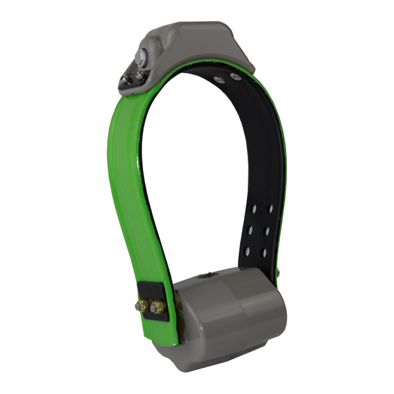
Figure 1: VERTEX Plus Collars: left: round collar for carnivores, right: oval collar for ungulate The basic VERTEX Plus Collar consists of the following components: - the electronic housing containing the GPS module, the VHF beacon, the optional sensors (activity/mortality/temperature), the communication modem (GSM/Iridium/ Globalstar), an UHF module and the UHF ID Tag (optional) ©... -
Page 11: Gps Receiver
The VERTEX Plus Collar - the magnet, which is attached to the electronic housing when the collar is in Stand-by- mode - the communication connector for the USB to VERTEX Plus Interface Cable - the battery pack with integrated battery connector and the Drop Off with magnet... -
Page 12: Vhf Beacon
Schedules. To change frequency and patterns follow the instructions in chapter Configuration. The VERTEX Plus Collar has three signal modes, the Standard Pattern (default: mode 0), the Mortality Pattern and the Emergency Pattern. The Mortality Pattern is active when your animal has not moved for a defined time (mortality period) (Mortality &... -
Page 13: Communication Options
The VERTEX Plus Collar Figure 3: Play Beacon Patterns Communication options The VERTEX Plus Collar is available with Iridium, Globalstar or GSM as remote communication. Follow the link to your chosen configuration. Iridium Globalstar 3.3.1 Iridium Communication Iridium offers a two-way communication which means you receive GPS data from the collar and can send new commands and schedules remotely to the collar. -
Page 14: Globalstar Communication
The VERTEX Plus Collar data packages come in later. For transmitting the data the collar needs clear view to the sky. The number of fixes defines the message size and thereby transmission time. How it works: The system uses 3 message blocks whereas the first block can contain 1-4 GPS fixes, the second block additional 8 at most (12 in total so far) and the third and last block additional 6. -
Page 15: Gsm Communication
The VERTEX Plus Collar Figure 5: Globalstar Coverage Map 2016 Each GPS position data is sent by the collar (1-2 Fixes per message). Data is sent out 3 times to increase transmission probability but data reception is not confirmed by the satellites. - Page 16 The VERTEX Plus Collar sent automatically via SMS to the defined phone number. If you wish to send new commands or schedules remotely, please contact our customer service under wildlife@vectronic-aerospace.com. Figure 6: GSM Communication For collar usage within Europe we provide GSM collars with VECTRONIC SIM chips so you do not have to take care about provider administration.
-
Page 17: Internal Sensors
The VERTEX Plus Collar Figure 7: GSM Ground Station NOTE: If no communication can be established between the GSM network and the collar or the GSM ground station, the GSM provider will retry to send the data. Data in the provider's memory are subject to a validity period. If no contact has been established within this period (usually 2-3 days, but depending on the provider's conditions), the data stored by the provider will be deleted without delivery. -
Page 18: Temperature Sensor
GPS and GSM / satellite contact from a cave or den. NOTE: Please consult VECTRONIC Aerospace regarding the hibernation settings. Wrong settings may result in loosing contact with the collar. -
Page 19: Proximity And Separation Sensor
The proximity sensor in the VERTEX Plus Collar with UHF communication is able to receive ID codes within a range between 5 and 500 meters, depending on ID Tag, collar settings and environmental issues. - Page 20 The VERTEX Plus Collar NOTE: Signal strength does not provide reliable information about the distance between two collared animals. If an ID code has been received by the proximity sensor, an alternative GPS schedule can be activated. This way the frequency of GPS fixes can be intensified. The proximity GPS schedule can stay active for a configurable period of time after the last ID code has been received.
- Page 21 The VERTEX Plus Collar proximity sensor on a VERTEX Plus Collar (red) if the UHF tag is within the radius of the sensor (app. 100 m). The IDs of the tags in range (ID1, ID2, ID3) are stored in the collars memory. ID4 is out of range.
-
Page 22: Uhf Radio Communication
The VERTEX Plus Collar message at the end of the active time. UHF Radio Communication The UHF Radio Link can establish contact with your collar every time you are in UHF range of the collared animal. If you have UHF Communication in your collar you can download data (except acceleration raw data) and upload schedules also remotely via the UHF Handheld Terminal. - Page 23 The VERTEX Plus Collar Points, a complex Virtual Fence can be created and stored as Virtual Fence Collection (VFC). Figure 12: Two examples for Virtual Fence polygons with Inside Point (a) inside and (b) outside of the polygon. The blue area indicates where the Virtual Fence settings are applied.
- Page 24 The VERTEX Plus Collar Figure 13: GPS schedules in relation to Virtual Fence area. 12:00: The bear is outside of the Virtual Fence and the standard GPS schedule is active, taking one position per hour. 12:30: The bear is inside the Virtual Fence, but the collar does not detect this until it obtains the first fix according to the standard schedule.
- Page 25 The VERTEX Plus Collar [2] On- Message on Enter [3] On- Message on Leave [4] On- Message on Enter and Leave Corners of the polygons are defined by their longitude and latitude. You can set the corners as “posts” in GPS Plus X, but you can also import a polygon from Google Earth as .KML file.
-
Page 26: Virtual Fence In Gps Plus X
The VERTEX Plus Collar the green polygon, which is partly inside the yellow polygon. The Virtual Fence area covers all terrain outside the yellow polygon plus the terrain inside the green polygon; this also includes the areas in which the green and yellow polygons overlap. - Page 27 The VERTEX Plus Collar A Virtual Fence consists of several posts and an Inside Point. The Inside point defines the area of interest; If the point is inside the fence the area of interest is surrounded by the fence, if the point is outside everything but the fence is area of interest.
-
Page 28: 3.6.1.1 Virtual Fence In Google Earth
The VERTEX Plus Collar Edits the selected fence post. A new window will open (Figure below), in which you can edit the post’s coordinates and name. The post you are currently editing is highlighted in green in the fence schematic. - Page 29 The VERTEX Plus Collar Figure 18: Google Earth - Creating a Virtual Fence Convert it into a KML file: File - Save - Saving As Import it in GPS Plus X under: collar – configuration - Virtual Fence Polygons In GPS Plus X: Imports a .KML file from Google Earth into the Virtual Fence Editor.
-
Page 30: Drop Off
The VERTEX Plus Collar Exports a fence (active fence only, not the complete Virtual Fence Collection) as .KML file to view in Google Earth. Please note: Sending Virtual Fences via cable and remotely makes a difference. Via cable and Handheld Terminal, you can send up to 4000 bytes, approximately 600 posts. -
Page 31: External Sensors
Separation. ID tags can be deployed to a belt, an expandable fawn collar or they can be integrated into a VERTEX Plus Collar. There is also the possibility for a stationary UHF- ID Tag. ID Tags can be equipped with a mortality sensor and a VHF beacon transmitter. -
Page 32: Expandable Fawn Collars
The VERTEX Plus Collar For more information please contact our customer service. 3.8.2 Expandable Fawn Collars Expandable Fawn Collars can be equipped with UHF ID Tags. The Expandable Fawn Collar is very light and made of elastic material which is folded in several layers. The layers are sewed together with cotton yarns which allow the layers to unfold with the effects from wear, time and weather. -
Page 33: Mortality Implant Transmitter (Mit)
Separation: The VIT continuously transmits an ID signal via UHF frequency to the VERTEX Plus Collar. When the mother moves away from the calving site, the ID signal is not received any longer. The VERTEX Plus Collar will send a separation message after one hour has passed without detecting the ID signal (default settings). -
Page 34: Data Formats
If no motion has been detected for a user definable period of time, the animal is presumed dead and a mortality alert with the current GPS position data is sent. The VERTEX Plus Collar's VHF beacon will also switch to mortality mode. - Page 35 File for data exchange with GPS devices .KML Google Earth file to display tracks, points of interest… .KMZ KMZ Zipped Google Earth file .BTX BioTelemetry eXchange VECTRONIC-defined XML-format .GDX GPS Data eXchange Is a XML format defined by VECTRONIC © 2017 VECTRONIC Aerospace GmbH...
- Page 36 2-axis Activity Data File .ADF3 3-axis Activity Data File Upload files .vbsf Beacon Schedule File VHF beacon schedule of VERTEX Plus Collar .vgsf GPS Schedule File GPS schedule of VERTEX Plus Collar .vcsf Communication Schedule File Communication Schedule of VERTEX Plus Collar .vesf External Sensor Schedule File...
-
Page 37: System Set-Up
Plus X software, you need to register the collars. The keys for each collar will be provided with the User-CD which came with the collars. For registering the collar, please go to the Configuration frame in GPS Plus X and select Configuration Collars. © 2017 VECTRONIC Aerospace GmbH... - Page 38 If you add the details before registering the collar, the registration status of the collar will be invalid. After registration, the entry of the corresponding collar will change from invalid to valid. For more information on collar registration, refer to the GPS Plus X Manual. © 2017 VECTRONIC Aerospace GmbH...
-
Page 39: Usb To Vertex Plus Interface Cable
NOTE: Please do not use any other cables than the USB to VERTEX Interface Cable to connect your VERTEX Plus Collar to your computer. You may destroy the communication connector of the collar which makes it impossible to load or upload data and schedules directly. -
Page 40: Test The Collar
NOTE: To save battery life, leave the magnet on the collar during storage and do not leave the collar connected to your computer if you do not use it. Disconnect the battery pack if you store the collar for months. Collar Main Tree Devices VERTEX Plus Collar © 2017 VECTRONIC Aerospace GmbH... -
Page 41: Information
Collar Main Tree The Devices frame is the main tool to manage your VERTEX Plus Collar in any respect. In the following chapter you get more information about all available options for your VERTEX Plus Collar, such as data download, data upload and configuration. -
Page 42: Telemetry
The Telemetry window gives an overview about all hardware and software settings of the collar. It shows the actual programming with no option to change it here. This topic informs you about definitions used in the Telemetry window. © 2017 VECTRONIC Aerospace GmbH... - Page 43 Collar Main Tree Figure 30: VERTEX Plus Collar Telemetry © 2017 VECTRONIC Aerospace GmbH...
- Page 44 Sample Rate Select defines how many measurements the sensor takes per second Temperature defines if temperature sensor is on / off Communication Tab: Radio information about the Transmit Frequency, Receive Frequency and Transmit Power of the collar © 2017 VECTRONIC Aerospace GmbH...
- Page 45 GSM modem starts to send data Beacon Tab: Beacon Frequency frequency of the VHF beacon: the default frequency which was set by VECTRONIC Aerospace and the User defined frequency values of the beacon min. frequency and the Beacon max. frequency are shown Beacon Power...
-
Page 46: Gps Monitor
GPS Warmstart: This button will initiate a warmstart of the collar. The GPS receiver will use the Ephemerides and other data already stored in the collar (flash memory, remains there for roughly 2hours) and only complete them with actual satellite data. © 2017 VECTRONIC Aerospace GmbH... -
Page 47: Info File
Every schedule is shown in a version which can be easily read and in the .XML format which is machine readable. Below you can see an extract of an Info File of the VERTEX Plus Collar. Recommendation: Create and save a new Info-Sheet whenever you have the collar at hand and did any changes, especially before deployments. -
Page 48: Configuration
Collar Main Tree Figure 32: Info File For definitions of terms used in the Info File please refer to Telemetry. Configuration Devices VERTEX Plus Collar Configuration © 2017 VECTRONIC Aerospace GmbH... -
Page 49: User Configuration
(see below). In this window, the range of possible values to choose will appear (Min value and Max value). Depending on the kind of data which is edited, the window shows different values. © 2017 VECTRONIC Aerospace GmbH... - Page 50 A short period might lead to false alarms as the animal is only resting. Hibernation Period You can define the time after which the collar switches back to normal mode if the activity is higher than the wake-up threshold. © 2017 VECTRONIC Aerospace GmbH...
- Page 51 (shown in the small pop up window). NOTE: Signal strength is best with the primarily set value (hardware dependent), signal strength will slightly decrease at the rim. © 2017 VECTRONIC Aerospace GmbH...
- Page 52 Shows the sensitivity of the proximity receiver in dbm. ID Blacklist: Shows which ID Tags will be ignored if a signal is received. ID Whitelist: Shows which ID Tag contact will create a reaction immediately. © 2017 VECTRONIC Aerospace GmbH...
- Page 53 Do not hesitate to ask us for further information. If you have a problem understanding the vocabulary of this topic you will find some definitions at Telemetry (Telemetry window definitions) © 2017 VECTRONIC Aerospace GmbH...
-
Page 54: Time
Collar Main Tree For more information please read the VERTEX Plus Collar Chapter carefully or just contact our customer service. 6.2.2 Time Devices VERTEX Plus Collar Configuration Time The Time frame displays: - Current Collar Time (UTC: Time, Date) - PC Time (Time, Date) -
Page 55: Virtual Fence Polygons
Virtual Fence Collections (.VFC) and can be uploaded to the collar via cable, UHF Handheld Terminal, GSM, and Iridium. For detailed information on shapes, combinations of several polygons of a Virtual Fence refer to 7.2.6 Functionality of sensors: Virtual Fence. © 2017 VECTRONIC Aerospace GmbH... - Page 56 .KML file into GPS Plus. You can do this by clicking on the item or Import Fence… from the Files menu. The name of the file will be the name of the fence. If you have multiple polygons in the .KML file, only the first will be imported. © 2017 VECTRONIC Aerospace GmbH...
- Page 57 2”, but “inside polygon 1 but not inside polygon 2” is not possible. If the collar is inside at least one of these polygons it uses the Virtual Fence schedule, otherwise it uses the standard GPS schedule. © 2017 VECTRONIC Aerospace GmbH...
-
Page 58: Start Bootloader
Bootloader frame. You should not do this unless you experience problems with the current collar firmware or need a feature only available in a newer version than the present one. In this case, get the appropriate file from VECTRONIC Aerospace and start the Bootloader. - Page 59 Figure 40: Bootloader Mode First, you need to upload the new firmware. Click on "Firmware Upload" and browse ( ) your computer for the firmware file you got from VECTRONIC and click the 'Start' button. © 2017 VECTRONIC Aerospace GmbH...
- Page 60 Collar Main Tree Figure 41: Upload Firmware When the upload process is finished, click on "Start Firmware" and the collar will switch back to 'Normal mode'. Figure42: Start Firmware © 2017 VECTRONIC Aerospace GmbH...
-
Page 61: Schedules
It always requires battery power to send, receive, or record data so you should spend some serious thoughts on schedules before collar deployment. VERTEX Plus Globalstar: You cannot upload schedules via satellite due to the one-way communication system. © 2017 VECTRONIC Aerospace GmbH... - Page 62 Clears the tool window to start schedule Loads a previously saved schedule Saves a created schedule for later usage and control Prints out the listed rules Schedule builder tool: add a new rule Schedule builder tool: delete selected rule © 2017 VECTRONIC Aerospace GmbH...
- Page 63 Rate – data recording repetition rate NOTE: You can only record data within the time span of the period. This way, the sum of offset and duration must be smaller than the value of the defined period length. © 2017 VECTRONIC Aerospace GmbH...
- Page 64 If you want to create a new schedule for the first time (only the default schedule exists in the collar), a notification window appears when selecting the schedule frame. Figure 47: Notification- Default schedule Please refer to following subtopics of the Schedules Node for deeper information © 2017 VECTRONIC Aerospace GmbH...
-
Page 65: Gps & Beacon Files Upload
It highly depends on your studies and the species how many GPS fixes the collar should take per day. GPS Scheduling differs between the 3 variants of the VERTEX Plus Collar you can have © 2017 VECTRONIC Aerospace GmbH... - Page 66 You can start with a low number of fixes to get an overview of how many fixes you really need and how your animal behaves, it is possible to change schedules remotely. But you should pay attention to the file size of your schedule (Figure: schedule file size), it © 2017 VECTRONIC Aerospace GmbH...
- Page 67 01.01.2000. If the collar's time is reset for any reason, the timer will start at this date and will attempt to take one fix per week until another schedule starts or until the clock is set to the correct UTC time by a successful GPS fix. © 2017 VECTRONIC Aerospace GmbH...
-
Page 68: Beacon Schedule
4 hours with a Period Length of 1 day, the VHF beacon will be active every day from 6.00 am to 10.00 am. In difference to the GPS schedule, you can define max. 372 VHF beacon schedule rules. Figure 50: Example Beacon Schedule © 2017 VECTRONIC Aerospace GmbH... -
Page 69: Communication Schedule
You can define a GPS schedule as proximity schedule. It is created and uploaded the same way as the standard schedule, but you need to select the proximity GPS schedule node. For information regarding the proximity application please refer to Proximity Sensor. © 2017 VECTRONIC Aerospace GmbH... -
Page 70: Virtual Fence Schedule
Reads data from the collar and displays it in the frame; this is not done automatically as the download of data can take several seconds to minutes. © 2017 VECTRONIC Aerospace GmbH... -
Page 71: Remote Collar (Communication)
Iridium or GSM communication. For remote communication go to Devices Remote Collars Vertex Collars Figure 52: Remote Vertex Collars Refer to the subtopics to learn how to communicate with the collar remotely. © 2017 VECTRONIC Aerospace GmbH... -
Page 72: Remote User Configuration
NOTE: Please keep track on your changes (collar journal) for you and your planning but also for us if you need support at some point. Remote User Configuration Devices Remote Collars VERTEX Collars User Configuration © 2017 VECTRONIC Aerospace GmbH... - Page 73 All options are explained in Chapter User Configuration and Telemetry. NOTE: Please keep in mind that some changes will affect not only the collar but also your ability to reset them. All changes should be well planned and documented. © 2017 VECTRONIC Aerospace GmbH...
- Page 74 6. Follow up on collar command reception (in Data Collar Reception Status) NOTE: check the changes before sending them as you might have problems to change them again (e.g. adding skip count, raising positions / messages fewer messages © 2017 VECTRONIC Aerospace GmbH...
-
Page 75: Remote Gps Schedule
An Iridium / GSM message to the collar can contain 108 bytes only, respectively 5-9 VHF Beacon rules. You might have to stick to some more basic rules, respectively plan for a certain period and resend updates from time to time. © 2017 VECTRONIC Aerospace GmbH... -
Page 76: Remote Proximity Schedule
There is a size limitation for Iridium / GSM Messages which means you won’t be able to make new ones as complex as the first one. An Iridium / GSM message to the collar can contain 108 bytes only. Remote Virtual Fences Devices Remote Collars VERTEX Collars Virtual Fences © 2017 VECTRONIC Aerospace GmbH... -
Page 77: Calculate Collar Lifetime
108 bytes. Calculate Collar Lifetime This command estimates the lifetime of your VERTEX Plus Collar and can be found in the Tools menu of GPS Plus X. Please select Calculate Vertex Collar Lifetime and type in all your configurations. - Page 78 (fixes within an hour). RECOMMENDATION: Please calculate with the Average scenario to start with, especially when you use a Globalstar collar or work in forested habitats. © 2017 VECTRONIC Aerospace GmbH...
-
Page 79: Battery Options
Battery options Battery options The VERTEX Plus Collar enables the usage of different battery sizes to fit a wide range of species and study scenarios. All batteries can be coupled with a Drop Off system. The battery design itself depends on the belt shape (oval, round and oval/round) and the usage of a Drop Off system. -
Page 80: Changing Of Battery Pack
There are 3 different belt shapes. For each shape the battery changing procedure differs a little. Please follow the links for the respective instructions. Oval collar Round Collar, standard battery pack Round collar, curved battery pack 10.1 Oval Collar © 2017 VECTRONIC Aerospace GmbH... -
Page 81: 10.2 Round Collar, Standard Battery Pack
NOTE: After you changed the battery pack of your collar, a GPS coldstart is necessary. For this please refer to Monitor. 10.2 Round Collar, standard battery pack Figure 60: Battery connector on round collar, standard battery pack © 2017 VECTRONIC Aerospace GmbH... -
Page 82: 10.3 Round Collar, Curved Battery Pack
Figure 62: Battery connector on round collar, curved battery pack First remove the nuts for closing the collar with an 8 or 7 mm (depending on collar size) hexagon socket wrench (Figure above, center), then open the screws attaching the © 2017 VECTRONIC Aerospace GmbH... - Page 83 Above you can see the battery socket (left) and pins (right). To attach a new battery pack, exchange the O-ring on the battery plug and carefully plug the three threaded battery pins into the socket. © 2017 VECTRONIC Aerospace GmbH...
- Page 84 Take care to arrange the screw correctly to avoid damaging the thread. Countersink the screws into the battery pack. NOTE: After you changed the battery pack of your collar, a GPS coldstart is necessary. For this please refer to Monitor. © 2017 VECTRONIC Aerospace GmbH...
-
Page 85: Collar Deployment
© 2017 VECTRONIC Aerospace GmbH... -
Page 86: Specification
Storage humidity range: <= 100% RH (relative humidity) Battery: Do not short-circuit, recharge, puncture, incinerate, crush, immerse or expose battery to temperatures above the declared operating temperature range of the product. Risk of fire or explosion! Storage: © 2017 VECTRONIC Aerospace GmbH... -
Page 87: 12.2 Declarations Of Conformity
This device complies with Part 15 of the FCC Rules. Operation is subject to the following two conditions: this device may not cause harmful interference, and this device must accept any interference received, including interference that may © 2017 VECTRONIC Aerospace GmbH... - Page 88 EN 301 489-1,-3 V1.8.1 / V 1.4.1 EMC for SRD 9 kHz – 40 GHz EN 301 489-20 V1.2.1 EMC for Mobile Earth Stations (MES) used in the Mobile Satellite Services (MES) EN 60950-1:2006 Safety of information technology equipment © 2017 VECTRONIC Aerospace GmbH...
- Page 89 +49 (0) 30 6789 5230 “ ” The product carries the CE mark Berlin, 2010-08-23 ..... . Robert Schulte © 2017 VECTRONIC Aerospace GmbH...
-
Page 90: 12.3 Certificates
Specification 12.3 Certificates © 2017 VECTRONIC Aerospace GmbH... - Page 91 Specification © 2017 VECTRONIC Aerospace GmbH...
- Page 92 Specification © 2017 VECTRONIC Aerospace GmbH...
- Page 93 Specification © 2017 VECTRONIC Aerospace GmbH...
- Page 94 Specification © 2017 VECTRONIC Aerospace GmbH...
- Page 95 Specification © 2017 VECTRONIC Aerospace GmbH...
- Page 96 Specification © 2017 VECTRONIC Aerospace GmbH...
- Page 97 Specification © 2017 VECTRONIC Aerospace GmbH...
- Page 98 Specification © 2017 VECTRONIC Aerospace GmbH...
- Page 99 Specification © 2017 VECTRONIC Aerospace GmbH...
Need help?
Do you have a question about the VERTEX Plus Collar and is the answer not in the manual?
Questions and answers