Table of Contents
Advertisement
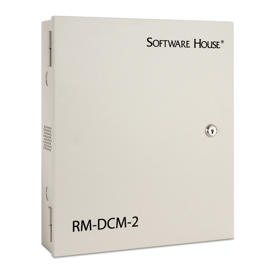
OVERVIEW
The RM-DCM-2 is a UL294 Listed and UL1076 Listed door control
module that includes the RM-4E Reader Module (RM-4E) and enclosure.
The RM-DCM-2 is designed to support up to two RM-4E modules,
providing a single enclosure for doors with IN and OUT readers.
The enclosure also has space for up to three I/8 and/or R/8 boards, for a
total of four boards. The RM-DCM-2 supports an optional battery (12
VDC, 4A), which will be recharged by the RM-4E battery charging circuit.
The RM-4E board provides the hardware interface between Magnetic
signaling read heads or Wiegand signaling read heads and the apC/8X,
iSTAR, and iSTAR Pro hardware. The RM-4E also provides inputs and
outputs that communicate between door components and the apC/8X,
iSTAR, and iSTAR Pro hardware.
The I/8 module provides eight supervised inputs and the R/8 module
provides eight dry contact, Form C relay outputs.
The RM-DCM-2 system consists of two subassemblies:
Model RM-DCM-CAN enclosure
Model RM-4E board
NOTE
For information about the RM-4E, I/8, or R/8 modules, refer to the Quick
Start guides listed in Table 13.
NOTE
All interconnecting products or devices must be UL Listed.
RM-DCM-2
Quick Start
Installation Guide
Document Part Number UM-215
Version H0
March 2018
1
Advertisement
Table of Contents

Subscribe to Our Youtube Channel
Summary of Contents for Software House RM-DCM-2
-
Page 1: Quick Start
Document Part Number UM-215 March 2018 OVERVIEW The RM-DCM-2 is a UL294 Listed and UL1076 Listed door control module that includes the RM-4E Reader Module (RM-4E) and enclosure. The RM-DCM-2 is designed to support up to two RM-4E modules, providing a single enclosure for doors with IN and OUT readers. - Page 2 Overview Table 1 lists the RM-DCM-2 board and enclosure offered by Software House. You can install an RM-DCM-2 up to 4000 feet (1219 meters) from /8X, iStar or iSTAR Pro hardware. TABLE 1. RM-DCM-2 Product Offering Product Description Enclosure RM-DCM-2...
-
Page 3: Rm-Dcm-2 Unit
RM-DCM-2 Unit RM-DCM-2 UNIT Figure 1 shows the RM-DCM-2 unit with one RM-4E board, an optional battery, and LCD. NOTE UL has evaluated this configuration only. Battery RM-4E FIGURE 1. RM-DCM-2 with Battery and LCD FEATURES RM-DCM-2 features include: LED status indicators – display RS-485, inputs, outputs, and power ... -
Page 4: Optional Equipment
Figure 2 shows an RM-DCM-2 unit with one RM-4E, R/8, I/8, and battery. There could also be another RM-4E board, I/8, or R/8 mounted... -
Page 5: Tamper Switch
FIGURE 2. RM-DCM-2 with RM-4E, R/8, I/8, and Battery Tamper Switch The RM-DCM-2 provides a tamper switch as part of the enclosure. 1. Verify or connect the normally closed tamper switch in the enclosure to the 2-pin connector labeled TAMPER (SW2) on the RM-4E board. See Figure 2. -
Page 6: Rm-4E Reader Interface
RM-4E Reader Interface RM-4E READER You can interface read heads that supply Wiegand signaling or magnetic (ABA) signaling to the apC/8X, iSTAR, and iSTAR Pro using RM-4E INTERFACE boards. Figure 3 indicates how an RM-4E board interfaces with Wiegand and Magnetic signaling read heads. - Page 7 RM-4E Reader Interface Figure 4 shows the photograph of an RM-4E board with LCD. RM-4E Layout FIGURE 4. Photograph of RM-4E Board...
- Page 8 This section lists the RM-4E components — starting from the upper right corner of Figure 5 and moving in a clockwise direction. Tamper The RM-DCM-2 tamper input twisted pair wires, shown in Figure 2, are connected to the TAMPER (SW2) input pins.
- Page 9 RM-4E Components There are two ways to power an RM-4E: Power In Method A - from the Power In connector using an external power supply, which also charges the battery through the BATTERY connector. Method B - from the RS 485 connector using the apC or iSTAR power ...
-
Page 10: Led Connector
RM-4E Components Method B - via RS-485 (RM Bus Connector) Connect +12 VDC to Pin 1 of the RS-485 connector on the bottom right side. Connect Ground (Gnd) to Pin 4 of the RS-485 connector. NOTE The +12 VDC input on Pin 1 has a protection diode that prevents you from using the RS-485 connector as a source of +12 VDC if you power through the Power IN connector. - Page 11 RM-4E Components NOTE When the wiring gauge is too small or the wiring runs are too long, the Yellow LED drive oscillation can cause cross-talk and result in misreads. RS 485 Reader Bus RS 485 is the reader bus connection to the apC or iSTAR. It is two wire, half duplex RS 485.
-
Page 12: Lock Connectors
+5 VDC +5 VDC if required Ground +12 VDC +12 VDC if required (not used by Software House magnetic read heads) NOTE UL has not evaluated magnetic (ABA) signaling read heads. Relay 1, Relay 2, The RM-4E provides lock components that facilitate connecting magnetic and electric strike locks. -
Page 13: Lock Wiring Configurations
Lock Wiring Configurations FIGURE 7. Lock Connectors LOCK WIRING RM-4E lock connectors support the following wiring configurations: CONFIGURATIONS Magnetic Lock using Relay 2 Electric Strike using Relay 2 Electric Strike using Relay 1 The following sections describe how to connect each configuration. The electric strike examples are shown as Fail-Secure. - Page 14 Lock Wiring Configurations FIGURE 8. Magnetic Lock Wiring with Jumper Options...
- Page 15 Lock Wiring Configurations This section describes the components and connections for magnetic lock Magnetic Lock wiring. Components Power Supply The power for a magnetic lock must be filtered, regulated direct current (DC) voltage. Alternating current (AC) does not work and half wave rectified DC does not work reliably.
-
Page 16: Electric Strikes
Lock Wiring Configurations You have the option of wiring to the normally open (NO) connector of Relay 2 if you want to have the Magnetic lock unlock under those conditions. If you use the normally open (NO) connector then Relay 2 will have to be normally energized using the C•CURE Administration application. - Page 17 Lock Wiring Configurations FIGURE 9. Relay 2 Fail Secure Wiring...
-
Page 18: Electric Strike Components
Lock Wiring Configurations This section describes components and connections for electric strike Electric Strike wiring using Relay 2. Components Bypass Switch Connect the J15 Bypass jumper (closed) to provide the internal connection from Maglock Pin 1 to the C contact of Relay 2. Do not connect an external bypass switch. - Page 19 FIGURE 10. Relay 1 - Fail Secure Wiring INPUTS Input 1 and Input 2 Connect inputs using the standard Software House supervision for either NO or NC. Figure 11 shows an example of wiring Normally Open (NO) and Normally Closed (NC) inputs.
- Page 20 Inputs NOTE To comply with UL requirements, use shielded, minimum 22 AWG stranded, twisted pair cable for monitor points, DSMS, and REXs. Use Belden 9462 or equivalent. LED Input Status Each input uses a Red, Yellow, or Green LED to show the input status. Only one color will be on at a time for each input.
- Page 21 Inputs SW 5 DIP Switch Functions The SW 5 DIP switch on the RM-4E is similar to the SW 3 DIP switch on the RM-4. TABLE 8. SW 5 DIP Switch on RM-4E and SW 3 DIP Switch on RM-4 SW 5 DIP Switch Equivalent DIP Function...
-
Page 22: Led Control
LED Control LED CONTROL SW5-3 and SW5-2 control the reader LED display. SW5-3 and SW5-2 provide the same LED control that is available on the RM-4 and the iSTAR ACM. Table 8 shows the possible settings of SW5-3 and SW5-2. TABLE 9. - Page 23 LED Control RM LEDs Table 9 describes the various conditions indicated by the red, green, and yellow RM reader LEDs. TABLE 10. RM Reader LED Indications Red LED Yellow Green Indication Brief flash Brief flash Brief flash Power up Online (software flag enabled) Online Offline or reader tamper Solid for 1 sec.
- Page 24 LED Control When SW 5-3 is On and SW5-2 is Off, the function is External Bi-color External Bi-color LED because there are two LEDs (Red and Green) in the reader. Control The LEDs will appear as Yellow when both Red and Green are on, making the function essentially a Tri-color (Red, Green, Yellow).
- Page 25 LED Control One Wire (Yellow) With one wire, the Yellow drive is wired as shown in Figure 14. The Yellow LED drive gets inverted in the read head resulting in a Red LED when the signal is low and a Green LED when the signal is high. If the Yellow LED drive is oscillating, the Red and Green LEDs will be oscillating and will appear to the human eye that the LED is Yellow.
- Page 26 LED Control When SW5-2 is On, it specifies One Wire (A,B,C) mode. In this case, a One Wire (A,B,C) LED single LED drive (Red or Green or Yellow) is wired with varying results Control as shown in Figure 15. One wire mode is typically used for older read heads with a single LED that is either On, Off, or flashing.
-
Page 27: Installation Requirements
Installing the Enclosure Make sure the installation location provides sufficient space for the RM- DCM-2 enclosure, and the necessary electrical conduit. Figure 16 gives the dimensions in inches for mounting the RM-DCM-2 enclosure. FIGURE 16. RM-DCM-2 Enclosure Dimensions (in Inches) -
Page 28: Module Dimensions
Maximum component height is 0.5 inches (12.7 mm). FIGURE 17. RM-4E, R/8, and I/8 Mounting Hole Dimensions Enclosures UL has approved the RM-DCM-2 enclosure for use with R/8, and I/8 boards. Mounting the RM-4E, R/8, and I/8 Boards To mount the RM-4E, R/8, and I/8 boards in an RM-DCM-2 enclosure, use four 1/4”... - Page 29 Operating temperature ranges for the RM-DCM-2 is 32-120° F (0-49° C); 85% relative humidity @ 86° F ± 3° (30° C ± 2°). The RM-DCM-2 is suitable for indoor use, to be installed within the protected premises. Connect the modules (RM-4E, I/8, R/8) to an RM reader bus on an iSTAR or apC.
-
Page 30: Power Requirements And Specifications
This section includes physical specifications and optimal operating specifications for the RM-DCM-2. SPECIFICATIONS NOTE UL has evaluated the RM-DCM-2 for indoor use with a range of 0° C to 49°C (32°F to 120°F). Current versions of C•CURE 9000 and C•CURE 800/8000 system Software and Firmware Support software and firmware support the RM-DCM-2 components. - Page 31 RM-DCM-2 Specifications TABLE 12. R/8 and I/8 Requirements and Operating Specifications Requirement Specification/Contact Ratings R/8 module power requirements 125mA at +12 VDC plus 25mA for each Active Relay R/8 relay contact rating - 2A at 30 VDC I/8 module power requirements...
-
Page 32: Physical Specifications
UM-204 R/8 Module optional AS-0074-000 R/8 Quick Start Guide optional UM-205 Compliance The RM-DCM-2 has been tested and certified for compliance with the standards listed below: UL Listed UL 294 UL 1076 Other FCC Part 15B class A ... -
Page 33: Required Equipment
This section describes the procedures that verify the RM-DCM-2 installation and operation. Required Equipment The following equipment is required. Two 1K resistors An LCD display module (2 line x 16 character), Software House part number RM-LCD Three LEDs A multi-meter to measure voltage and resistance ... -
Page 34: Self-Test Mode
Testing the RM-DCM-2 Self-Test Mode The RM-4E has a built-in self-test mode. Perform the steps in this section to run the self-test. 1. Remove power to the RM-4E. 2. Set Rotary Switch SW4 to position 0. 3. To test the reader LEDs, connect three LEDs to the Reader LED port as shown in Figure 19. - Page 35 Testing the RM-DCM-2 Indicates the state of supervised Indicates the state of the inputs Input 1 and Input 2: reader port connections (D1 line, D0 line, and DAT line, in 0 = Open that order): 1 = Secure 0 = Closed...
-
Page 36: Manual Test Procedure
K3 is the keypad connector number and 0 is the new state. Manual Test Procedure To manually test the RM-DCM-2: 1. Measure the supply voltage to the RM-4E. The voltage can be measured between pin 1 (ground) and pin 2 (supply) on the Power-In connector. - Page 37 CE Notice The corresponding LED (DS3 for output #1 and DS10 for output #2) will light. The multi-meter can be used to check for continuity between the C and NO pins on connectors Relay1 and Relay2. 6. Check the reader interface. The reader interface can only be tested with the reader chosen for the installation.
- Page 38 Information about other products furnished by Software House is believed to be accurate. However, no responsibility is assumed by Software House for the use of these products, or for an infringement of rights of the other companies that may result from their use.
Need help?
Do you have a question about the RM-DCM-2 and is the answer not in the manual?
Questions and answers