
Summary of Contents for Bristol Babcock 3310 Series
- Page 1 Instruction Manual CI-3310 RTU 3310 Nov., 2006 Remote Terminal Unit RTU 3310 www.EmersonProcess.com/Bristol...
- Page 2 IMPORTANT! READ INSTRUCTIONS BEFORE STARTING! Be sure that these instructions are carefully read and understood before any operation is attempted. Improper use of this device in some applications may result in damage or injury. The user is urged to keep this book filed in a convenient location for future reference.
- Page 3 WARRANTY Bristol warrants that goods described herein and manufactured by Bristol are free from defects in material and workmanship for one year from the date of shipment unless otherwise agreed to by Bristol in writing. Bristol warrants that goods repaired by it pursuant to the warranty are free from defects in material and workmanship for a period to the end of the original warranty or ninety (90) days from the date of delivery of repaired goods, whichever is longer.
- Page 4 How to return material for Repair or Exchange Before a product can be returned to Bristol for repair, upgrade, exchange, or to verify proper operation, form (GBU 13.01) must be completed in order to obtain a RA (Return Authorization) number and thus ensure an optimal lead time. Completing the form is very important since the information permits the Bristol Repair Dept.
- Page 5 Bristol Inc. Repair Authorization Form (off-line completion) (Providing this information will permit Bristol Inc. to effectively and efficiently process your return. Completion is required to receive optimal lead time. Lack of information may result in increased lead times.) Date___________________ RA #___________________SH_ Line No.____________ Standard Repair Practice is as follows: Variations to this is Please be aware of the Non warranty standard charge:...
- Page 6 Bristol Training GET THE MOST FROM YOUR BRISTOL BABCOCK INSTRUMENT OR SYSTEM • Avoid Delays and problems in getting your system on-line • Minimize installation, start-up and maintenance costs. • Make the most effective use of our hardware and software. •...
- Page 7 A Few Words About Bristol Inc. For over 100 years, Bristol has been providing innovative solutions for the measurement ® and control industry. Our product lines range from simple analog chart recorders, to sophisticated digital remote process controllers and flow computers, all the way to turnkey SCADA systems.
- Page 8 For technical questions regarding ACCOL products, OpenBSI Utilities, UOI and all other software except for ControlWave and OpenEnterprise products, call (860) 945-2286. For technical questions about Network 3000 hardware, call (860) 945-2502. You can e-mail the Application Support Group at: bsupport@bristolbabcock.com The Application Support Group maintains an area on our web site for software updates and technical information.
-
Page 9: Table Of Contents
CI-3310 - TABLE OF CONTENTS Page Section 1 - INTRODUCTION GENERAL OVERVIEW ........................... 1-1 HARDWARE STRUCTURES ........................1-3 Computing/communication Assembly (C/C Assembly)..............1-3 CIRCUIT OVERVIEW ..........................1-5 Multi-Function Interface Board (MFIB) ................... 1-5 CPU Engine Boards ........................... 1-5 80C186-Based CPU Engine ....................... 1-5 80386EX-Based CPU Engine Boards.................... - Page 10 CI-3310 - TABLE OF CONTENTS Page Section 3 - SETUP & WIRING GENERAL NOTES........................... 3-1 Wiring Practises ..........................3-1 I/O MODULE TERMINAL BLOCKS ...................... 3-1 Plug-In Features ..........................3-1 Preventing Mix-ups of Terminal Block Connectors ................. 3-1 Signal Labels on Terminal Blocks..................... 3-3 ASSOCIATED SECTIONS........................
- Page 11 CI-3310 - TABLE OF CONTENTS Page Section 3BA - 32-Bit CPU ENGINE BOARD - Real Mode (Continued) Jumper W1 (RAM Battery)......................3BA-6 LEDS ..............................3BA-6 Status LEDs DS1-DS6........................3BA-6 Watchdog and Idle LEDs DS7 & DS8..................3BA-6 Section 3BB - 32-Bit CPU ENGINE BOARD - Protected Mode Series 396030-XX-X &...
- Page 12 CI-3310 - TABLE OF CONTENTS Page Section 3DB - HIGH DENSITY ANALOG INPUT MODULE (Four or Eight AI Type) Series 392544-XX-X GENERAL............................3DB-1 TERMINAL DESIGNATIONS......................3DB-1 SELECTING 1-5V OR 4-20 mA INPUTS...................3DB-4 1-5 Vdc Isolated Inputs .........................3DB-4 4-20 mA Transmitter Using +24V DPC Power Source...............3DB-5 4-20 mA Transmitter Using Auxiliary +24V Power Supply ............3DB-6 SPECIFICATIONS ..........................3DB-7 Analog Input Specifications......................3DB-7...
- Page 13 CI-3310 - TABLE OF CONTENTS Page Section 3FA - HDDI BOARD (Sixteen HDDI Type) Series 392557-XX-X GENERAL............................3FA-1 LED On-Off OPTION - Jumper W17 ................... 3FA-3 TERMINAL DESIGNATIONS......................3FA-3 INTERNALLY-SOURCED RELAY CONTACT OR OPEN COLLECTOR DI ........................3FA-4 SINGLE-ENDED DRIVEN RELAY CONTACT DI ................. 3FA-4 DRIVEN DIFFERENTIAL RELAY CONTACT DI ................
- Page 14 CI-3310 - TABLE OF CONTENTS Page Section 3H - HIGH SPEED COUNTER MODULE (Continued) Series 392008-XX-X & 392028-XX-X SPECIFICATIONS ..........................3H-10 High Speed Counter Specifications ....................3H-10 Environmental Specifications...................... 3H-10 Section 3HA - HIGH SPEED COUNTER MODULE Series 400018-XX-X GENERAL............................3HA-1 Jumper Locations .........................
- Page 15 CI-3310 - TABLE OF CONTENTS Section 3J - HIGH SPEED ANALOG INPUT MODULE & SYSTEM (Continued) HSAIM Common Mode Rejection Ratio ..................3J-15 HSAIM Common Mode Voltage ....................3J-15 HSAIM Surge Suppression......................3J-15 HSAI Panel Inputs ......................... 3J-15 HSAI Panel Input Types........................ 3J-15 HSAI Panel Input Impedance .......................
- Page 16 CI-3310 - TABLE OF CONTENTS Section 6 – MULTI-FUNCTION INTERFACE BOARD SERVICE (Continued) Power Fail & Master Clear LEDS..................... 6-5 24V 0r 12V DC Supply Source......................6-5 DC Converter Outputs (+15, -15 & +5 V) ..................6-5 ADDITIONAL MFIB BOARD TESTS..................... 6-5 Loopback Test.............................
-
Page 17: General Overview
GENERAL OVERVIEW Series 3310 Small ACCOL Remote Terminal Units (RTU) are microprocessor- based controllers that can function as stand-alone units or as nodes of a Bristol Babcock NETWORK 3000™ system. The RTU monitors a number of process-related I/Os, maintains and analyzes real-time data, executes control algorithms based on the user's software configuration, and communicates with the network through a hierarchical scheme of master and slave units. - Page 18 Network 3000 Operation 3310 RTUs can function as remote nodes of a Network 3000 system together with Bristol babcock's family of distributed controllers (Series 3330, 3335, 3350 and 3380). The network nodes may be used in local area networks (LANs), wide area networks (WANs), or combinations of both.
-
Page 19: Hardware Structures
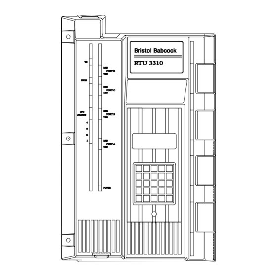
• Optional Fiber Optic Interface This option communicates data over fiber optic cable using coherent infra-red light transmission. It provides an asynchronous dual-link, single-channel capability at selectable rates from 300 Baud to 38.4 K-Baud (see Appendix FA for details). Figure 1-1 - 3310 RTU Assembly w/Plastic Covers HARDWARE STRUCTURE The 3310 RTU is available in two different packaging arrangements as follows: •... - Page 20 • An I/O Assembly in the form of a Multi-Function Interface Board (MFIB). The MFIB Board may include one optional Modem Board and can accept up to four I/O modules. • A CPU Engine Board Figure 1-2 - 3310 RTU in NEMA-4 Enclosure Figure 1-3 - Front View of 3310 RTU Chassis w/Full I/O Capability 1-4 / Introduction CI-3310...
-
Page 21: Circuit Overview
CIRCUIT OVERVIEW The PC boards and I/O modules contained in the 3310 RTU are shown in he block diagrams of Figures 1-5 & 1-6. A functional Description of each type follows: Multi-Function Interface Board (MFIB) (see Figure 1-4) The MFIB Board contains serial communication controllers, interface drivers and receivers, LED signal status indicators, 4 I/O card connectors, a connector for a modem, as-well-as a connector for a CPU Engine Board (refer to "CPU Engine Boards"... - Page 22 Figure 1-5 - Block Diagram of 186-Based RTU RAM may be specified with 128K, or 384K (bytes) of storage. RAM data is backed up by a 4000-hour lithium battery. RTUs may also be specified with a 64 k-byte EPROM-based ACCOL load; the EPROM is hard configured and is not dependent on power for load retention.
-
Page 23: Ex-Based Cpu Engine Boards
80386EX-Based CPU Engine Boards (see Sections 3BA & 3BB) A 32-bit embedded microprocessor functions as the CPU. This fully static microprocessor features low power and low voltage capabilities, and utilizes either a 16-bit (Real Mode) or 32-bit (Protected Mode) programming architecture. These boards may be furnished with 510 k-bytes of Base RAM, 512 k-bytes of Base FLASH Memory, and 128 k-bytes of Load/Boot Code FLASH Memory. -
Page 24: I/O Modules
Descriptions of the Real Mode (16-bit) and the Protected Mode (32-bit) versions of the 80386EX-based CPU Engine are provided in Sections 3BA and 3BB respectively. Back-up power is provided to RAM by a Lithium battery. The battery provides a cumulative back-up period of six months (4,500 Hours worst case) for Base RAM. With the addition of the EMB the back-up period diminishes as follows: EMB with 1M RAM - 3490 Hours worst case EMB with 2M RAM - 2830 Hours worst case... -
Page 25: Solid State Dc Relay Discrete Output Module
The Discrete Output Module contains an I/O bus interface, output status buffer and control circuitry. Surge suppression is also provided for each DO channel . Solid State DC Relay Discrete Output Module (see Section 3GA for details) 8 DOs: Normally Open/Normally Closed "opto-isolated" output - 3A, 38Vdc (Max) type SSDCRDO Modules provide 8 outputs which can be discretely configured (via on board jumper) for normally open or normally closed operation. -
Page 26: Hazardous Area Classification
The enclosure requirements are defined in ANSI/ISA Standards S82.01, S82.02 ans S82.03. All electrical wiring and grounding must conform with the requirements of the National Electrical Code and local inspection authorities. HAZARDOUS AREA CLASSIFICATION Equipment Approval FM-Approved models are designated for use in nonincendive for Class I, Division 2, Groups A, B, C and D hazardous locations. -
Page 27: Categories Of Application Software
1A.2 ACCOL TOOLS SOFTWARE ACCOL stands for Advanced Communications and Control-Oriented Language, and is Bristol Babcock's proprietary language for programming Network 3000-series controllers, such as the RTU 3310. The ACCOL compilers and related software are collectively referred to as the ACCOL Tools. Each of these tools will be discussed later in this section. - Page 28 When editing of the ACCOL program has been completed, it must be compiled and linked to generate an ACCOL object file (.ACO) and an ACCOL load file (.ACL). The ACCOL load file contains the original programming instructions in a machine-readable format which can be executed by the RTU 3310 control-ler.
- Page 29 To do the following: If you have 186-based If you have 186-based If you have 386EX Controllers, or 386EX Real Controllers, or 386EX Real Protected Mode Mode Controllers: Mode Controllers: Controllers: DOS-based ACCOL Tools Windows™-based ACCOL Windows™-based Version 5.13 Workbench (RM) Version 1.1 ACCOL Workbench (or newer RM version) or (PM) Version 6.3 or...
-
Page 30: Supervisory Software
1A.4 OPEN BSI UTILITIES SOFTWARE The Open Bristol System Interface (Open BSI) is a layer of communications software which provides access to a network of Bristol Babcock remote process controllers. Above this communications layer are a group of applications (programs) which are collectively known as the Open BSI Utilities. -
Page 31: System Applications
In addition to the standard set of Open BSI Utilities, just described, there are other utilities, available from Bristol Babcock as add-ons to the standard utilities, which provide capabilities for scheduled data collection, and file export. These utilities include the Open BSI Harvester and the Data File Conversion utility (see the Ooen BSI Harvester manual (document # D5120) for details. -
Page 32: Stand-Alone Unit
The PC for this application runs Bristol Babcock's ACCOL Workbench Software and Open BSI Utilities. Data stored in the RTU can be observed or edited via the Figure 1A-3 - Basic Stand-Alone Application Once on line, the RTU executes the ACCOL load and performs its configured tasks. - Page 33 Journaling and system configuration utilities can also be employed as required. The Bristol Babcock NETWORK 3000 BSAP system supports a maximum of five levels starting with the master device at level 1. Slave nodes at each descending level communicate upward through its preceding master node.
-
Page 34: Wide Area Network (Wan)
1A.5.3 Wide Area Network (WAN) WANs typically support the communications requirements of computers and equipment at numerous geographical locations and may encompass many local and remote sites. A Net- work 3000 system can also be constructed as a wide area network encompassing many local area networks. -
Page 35: Environmental Considerations
Section 2 INSTALLATION UNPACKING Unpack the equipment carefully. Your shipment may include items such as PC boards, mounting brackets and hardware (where applicable). Carefully inspect all cardboard inserts and cushioning material for any concealed items. Do not discard any packing material until all pieces of the shipment have been identified and sorted. -
Page 36: Esds (Electrostatic Discharge Sensitivity) Considerations
devices will often cure the problem but obstinate cases may require special line filters and improved equipment shielding and grounding. ESDS (Electrostatic Discharge Sensitivity) Considerations CAUTION Electrostatic discharge voltages can cause com- plete, or intermittent failure of the 3310 RTU. Read the ESDS Manual S14006 Care and Handling of PC Boards and ESD-Sensitive Components at the back of this manual before proceeding. - Page 37 Figure 2-1 - removal of Cover from 3310 RTU Figure 2-2 - Side View of Locking Snap CI-3310 Installation / 2-3...
-
Page 38: Installing Units
INSTALLING UNITS 3310 RTUs are intended for indoor, surface mounted applications. The overall mounting dimensions for the RTU given in Figures 2-3 and 2-4. A general installation procedure follows Figure 2-3 - Mounting Dimensions for 3310 RTU 2-4 / Installation CI-3310... - Page 39 Figure 2-4 - Mounting Dimensions for 3310 RTU (Continued) CI-3310 Installation / 2-5...
-
Page 40: Installing Nema-4 Enclosures
INSTALLING NEMA-4 ENCLOSURES RTUs furnished in NEMA-4 enclosures are intended for either indoor or outdoor installations. These enclosures are provided with a gasketed door and four, screw-type clamps to secure the door. A hasp is also provided for a user-supplied padlock. Indoor/Outdoor Mounting The overall dimensions for NEMA 4 enclosures are given in Figure 2-5. -
Page 41: Optional Communications Receptacle
Optional Communications Receptacle A rectangular opening in the case is provided for an optional communication receptacle that provides a connection to a personal computer (PC). This six-pin, water-tight receptacle is installed in this opening as shown in the dimensional drawing of Figure 2-5. The receptacle is provided with a hinged cover and clamping bar that shuts tight to protect the receptacle when it is not in use. -
Page 42: Plug-In I/O Termination
functions as a finger grip. When using the tool, apply a moderate pulling action to free the module from its socket. Plug-In I/O Termination It is not necessary to unwire each terminal when removing an I/O module from its slot. I/O modules utilize plug-in termination blocks that permit a rapid disconnect. -
Page 43: General Notes
Section 3 SETUP & WIRING GENERAL NOTES The RTU contains plug-in CPU boards and I/O modules. The PC boards provide computing and processing functions, while the I/O modules provide signal interface functions. Nearly all boards and modules will require some preliminary configuration that involves setting jumpers and switches. - Page 44 The terminal block connector fits very tightly in its socket. To unplug a connector, apply moderate downward pressure on the module with one hand while gripping the terminal block firmly with the other hand. Work the terminal block gently from side to side until it releases from the socket.
-
Page 45: Preventing Mix-Ups Of Terminal Block Connectors
Preventing Mix-ups of Terminal Block Connectors Each terminal block is keyed to prevent it from being plugged in upside-down. However, this keying does not prevent a terminal block from being plugged into the wrong I/O module. To minimize this risk, each terminal block has a label affixed to it that corresponds to the factory-assigned module slot. - Page 46 Table 3-1 - Associated Sections (Continued) SECTION TITLE SUBJECT Discrete Output Module (Four or Eight DO Type) Setup & Wiring Solid State Discrete Output Module Setup & Wiring High Density Discrete Output Module (Sixteen DO Setup & Wiring Type) High Speed Counter Module Setup &...
-
Page 47: Description
Section 3A MULTI-FUNCTION INTERFACE BOARD DESCRIPTION The Muti-Function Interface Board (MFIB) (Figures 3A-1 & 3A-2) provides plug-in connec- tions for each PC board and I/O module used in the RTU. It generates the +15 Vdc, -15 Vdc and +5 Vdc outputs from an integral DC-to-DC Converter, and also provides other precision voltages required to operate the RTU. - Page 48 Figure 3A-1 - MFIB Board (Series 392516-XX-X) (Through-Hole Version) 3A-2 / MFIB CI-3310 (03/03)
- Page 49 Figure 3A-2 - MFIB Board (Series 392901-XX-X) (Surface-Mount Version) CI-3310 (03/03) MFIB / 3A-3...
-
Page 50: Watchdog Terminals
WARNING Electrically powered equipment must be properly grounded to protect users from electrical shock and possible fatal injury. In addition to complying with local regulations, grounding should be performed in accordance with the National Electrical Code, ANSI/ISA standards S82.01, S82.02 and S82.03. Figure 3A-3 - Terminal Blocks TB1 and TB2 (Wiring labels) Figure 3A-4 - DC Power Connections Watchdog Terminals... -
Page 51: Board Operation
Figure 3A-5 - Watchdog Alarm Connections BOARD OPERATION Power Switch The MFIB Board contains a power switch (SW1) that turns off the +24 V (or +12 V) supply source as-well-as the internal power distribution (+15 Vdc, -15 Vdc, +5 Vdc and -5 Vdc. Although all internal power may be turned off, voltages from externally powered devices such as transmitters, transducers, on-off control elements, alarms, etc. -
Page 52: Communication Port Switches, Jumpers And Leds
When both jumpers are OUT, the power supply return is isolated from power common. Note that both jumpers must be set to the same position to achieve proper results. The recommended grounding arrangement for the 3310 is shown in Figure 3A-4. For this arrangement the dc supply return is referenced to the "Zero Reference Point"... -
Page 53: Leds
TABLE 3A-C - MFIB Board Jumpers JUMPER(S) FUNCTION(S) POSITION(S) W1A & W1B Connect power return to chassis Factory Installed Enables LEDs DS14 & DS15, for sequencer 1-2: Enables LEDs circuit PFIN LED and MC LED indicators. 2-3: Disables LEDs 1-2: Enables master reset on watchdog condition. - Page 54 BLANK PAGE...
-
Page 55: Description
Section 3B 12 MHZ CPU ENGINE BOARDS DESCRIPTION CPU Engine Boards contain a 12-MHz processor that performs the computing, control and communication functions of the RTU. These boards may be furnished with 128 K-byte or 384 K-byte RAM storage, and with an optional ACCOL EPROM load. Circuit Overview The CPU Engine Board (Figures 3B-1 &... - Page 56 Figure 3B-1 CPU Engine Assembly (Surface Mount.) Series 392902-XX-X (12 MHz) 3B-2 / 12MHz CPU Engine CI-3310 (09/01)
- Page 57 Figure 3B-2 CPU Engine Assembly (Through Hole) Series 392521-XX-X (12 MHz) CI-3310 (09/01) 12 MHz CPU Engine / 3B-3...
- Page 58 These switches function as follows: o 128/64 RAM Switch SW1-1 is factory-set to match the board's RAM capacity. This switch is OFF for 128 k or 384 k RAM. To determine the board's current RAM capacity, check the board's part number against Table 3B-A. NOTE: The ON position for this switch is for 64K, an option which is not available.
- Page 59 o A/B This selection is only used for the redundancy application. It assigns a Model 3332 Redundant DPC as the A or B unit (ON = A; OFF = B). For the Model 3310, this switch may be left in either position. TABLE 3B-A LISTING OF 392902-XX-X CPU BOARDS IC Designation 12 MHz...
-
Page 60: Switch Sw2 (Node Address)
TABLE 3B-B SWITCH SETTINGS FOR SW1 & SW2 (Continued) Switch Switch Function Number Selection SW1 - 8 Standard BSAP Slave Communications Extended BSAP Slave Communications SW2 - 1 Seven-Bit Node Address: to - 7 Bit value is 0 Bit value is 1 ON/OFF Not Used AR = As required. -
Page 61: Jumper W2 (Numeric Processor)
Jumper W2 (Numeric Processor) The numeric processor option (NPX) performs floating point arithmetic and transcendental operations. It includes integrated circuit assembly U12 as shown in Figures 3B-1 and 3B-2. When this option is present, W2 must be plugged in as noted in Table 3B-C. Jumpers W3-W9 (Memory Selection) Listed in Table 3B-C, jumpers W3 to W9 are set to correspond with the type and capacity of memory chips installed on the board. -
Page 62: Leds And Reset Button
LEDS AND RESET BUTTON Status LEDs LEDs DS1 to DS6 on the CPU Engine Board (Figures 3B-1 & 3B-2) provide a diagnostic status indication. The diagnostic failure patterns are described in "Section 5 Service." Watchdog & Idle LEDs The WDOG LED on the CPU Engine Board monitors the watchdog timer. This LED is normally OFF and turns ON if a failure is detected. -
Page 63: Low Byte And High Byte Matched Set
CAUTION RAM or EPROM chips can be damaged by static electric charges. Before adding or changing any chips, refer to instruction booklet S14006, furnished with this manual, for proper handling procedures. Low Byte and High Byte Matched Set When an EPROM chip pair is programmed, the user will assign separate identities to each unit. - Page 64 RAM chips in sockets U10 and U11 (see Figures 3B-1 & 3B-2 for location). Order the chip expansion set, pt. no. 390976-01-6 (for 12 MHz CPUs), from Bristol Babcock. Each chip provides 128 K x 8 memory storage. The chips must be oriented as shown in Figures 3B-1 and 3B-2 before pushing them into their sockets.
-
Page 65: Description
Section 3BA 32-Bit CPU ENGINE BOARD - Real Mode Series 392556-XX-X DESCRIPTION The 32-Bit CPU Engine Board is fully compatible with current 3310 boards and has been designed to provide the following enhancements: • Two additional BSAP Asynchronous Serial Ports. •... - Page 66 Figure 3BA-1 - 32-Bit CPU Engine Board - Real Mode 3BA-2 32-Bit CPU Engine - Real Mode CI-3310 (09/2001)
-
Page 67: I/O Interface
• Function Switch (SW1): An eight position switch (SW1) accommodates function assignment and is read from byte location 09F881 with the first switch set as the LSB. The open or OFF position is read as a 1. No hardware functions are controlled by SW1. Real-Time Clock: The CPU Board offers a Real-Time Clock with an accuracy of "... -
Page 68: Switch And Jumper Configuration
SWITCH AND JUMPER CONFIGURATION Prior to operation, the switches and jumpers of the CPU Engine Board must be checked. Function switch SW1 and node address switch SW2 define their OFF (open) positions as logic "1" and their ON (closed) as logic "0." Switch SW1 (Mode) Switch SW1 selects various board operating modes (see Tables 3BA-2 &... -
Page 69: Switches Sw1 -5, -6 - Accol Flash Lock/Accol Load Storage
Table 3BA-3 - Switch SW1 Baud Rate Settings Selection (Baud Rate) SW1-2 SW1-3 SW1-4 1200 2400 4800 9600 19200 38400 * Ports BIP1, A & C default to 9600 Baud when utilized for a cold download. Switches SW1 -5, -6 - ACCOL FLASH Lock/ACCOL Load Storage ACCOL loads can be stored in RAM or FLASH memory. -
Page 70: Switches Sw3 & Sw4
The cumulative back-up period lasts six months (4,500 hours maximum) for base RAM. Jumper W2 (WARNING) Jumper W2 should never be plugged in or have a jumper wire installed by the customer. It is for Bristol Babcock testing only. LEDs Status LEDs DS1-DS6 LEDs DS1 to DS6 on the CPU Engine Board (Figure 3BA-1) provide a diagnostic status indication. -
Page 71: Description
Section 3BB 32-Bit CPU ENGINE BOARD - Protected Mode Series 396030-XX-X & 392906-XX-X DESCRIPTION The "Protected Mode" 32-Bit CPU Engine Assembly is a two board set which is fully com- patible with current 3310 systems. The assembly consists of the 32-Bit CPU Engine Board and the Extended Memory Board (EMB). - Page 72 Series 396030-XX-X Figure 3BB-1 - CPU Engine Board Figure 3BB-2 - 32-Bit CPU Engine Ass'y. 3BB-2 32-Bit CPU Engine - Protected Mode CI-3310 (05/2003)
- Page 73 Series 392906-XX-X Figure 3BB-3 - 32-Bit CPU Engine Ass'y. CI-3310 (05/2003) 32-Bit CPU Engine - Protected Mode / 3BB- 3...
-
Page 74: Protected Mode 32 Bit Cpu Engine I/O Interface
• Battery: Back-up power is provided to all RAM by a Lithium battery. The battery provides a cumulative back-up period of six months (4,500 Hours worst case) for Base RAM. With the addition of RAM on the EMB (Extended Memory Board), used in conjunction with CPU Assemblies 396030-XX-X only, the back-up period diminishes as follows: EMB with 1M RAM - 3490 Hours worst case... - Page 75 • RS-485/EIA-562 Port Interface: Connector J2 contains built-in Port 1 [(BIP1) Pins 10 through 18] and built-in Port 2 [(BIP2) Pins 1 through 9] which are configured via SW3 & SW4 respectively. On-board 10KV ESD protection is provided. Cable Assemblies # 395414-01-6 (for Series 396030-XX-X CPUs) and 395414-05-9 (for Series 392906-XX-X CPUs) provide a 21-pin plug assembly which mates with connector J2.
-
Page 76: Switches Sw1 -2, -3, -4 - Cold Download Baud Rate
SWITCH & JUMPER CONFIGURATION & LEDs Prior to operation, the switches and jumpers of the 32-Bit CPU Engine Assembly must be checked. 32-Bit CPU Engine Board function switch SW1 and node address switch SW2 define their OFF (open) positions as logic "1" and their ON (closed) positions as logic "0." Two eight-position DIP Switches (SW3 &... -
Page 77: Bit Cpu Eng. Board Switches Sw1-6 - Accol Load Storage Sw1-4 - Accol Flash Lock
Note: SW1-8 "BSAP" is set to OFF only if unit is communicating with an expanded master, and in Group 1 or above. TABLE 3BB-2 - Switch SW1 Mode Lables Switch # Selection Mode Label Function Set To Normal SW1-1 FLASH Download FLASH Download SW1-2 Table 3BB-3... -
Page 78: Bit Cpu Engine Board Switch Sw2 - (Node Address)
overwritten. When SW1-6 and SW1-4 are set to the OFF position, the unit will not accept a new ACCOL FLASH download. Switch SW1-4 should not be set to the OFF position until SW1-6 has been set to the OFF position and a download has been completed. Note: The ACCOL FLASH Lock option (see Table 3BB-4) is not enabled until switches SW1 -2, - 3 and -4 have been re-defined by configuration of soft switches. -
Page 79: Bit Cpu Engine Board Reset Button Sw5
32-Bit CPU Engine Board Jumper W2 (CPU Tri-State Enable) Jumper W2 (WARNING) Jumper W2 should never be plugged in or have a jumper wire installed by the customer. It is for Bristol Babcock testing only. Extended Memory Board Jumpers W1, W2 & W3 (Factory Installed) Jumpers W1 through W3 are used to set FLASH RAM and Static RAM memory con- iguration. -
Page 80: Cpu Engine Assembly Number Assignments
Figure 3BB-5 - Card Edge End View of 392906-XX-X CPU Board Table 3BB-8 - Communication Port LEDs LED ON FUNCTION DS9-1 Transmit Data on BIP1 DS9-2 Receive Data on BIP1 DS9-3 Transmit Data on BIP2 DS9-4 Receive Data on BIP2 CPU ENGINE ASSEMBLY NUMBER ASSIGNMENTS The Protected Mode CPU assemblies listed below may be used in the RTU 3310: 396030-01-7 - 32-Bit CPU with 0MB RAM without FP... -
Page 81: General
Section 3D ANALOG INPUT MODULE (Four AI Type) Series 392009-XX-X, 392029-XX-X & 392086-XX-X GENERAL Analog Input Modules with four AIs are available with the ranges and features given in the Table 3D-A. Modules having 1-5 V and 4-20 mA input ranges can be configured for either range by jumper arrangement. - Page 82 Figure 3D-2A - AI Module (1-5 V / 4-20 mA Type Shown w / Mass Term. Connector) (w/o Common Mode - left diagram - w / Common Mode - right diagram ) (For 3330s, 3331s & 3335s) 3D-2 / AI Module CI-3310/30/35 (08/2006)
- Page 83 Figure 3D-2B - AI Module (0-10 V Type Shown w / Straight Term. Connector) (w / Common Mode - left diagram - w/o Common Mode - right diagram ) (For 3310s & 3330s) CI-3310/30/35 (08/2006) AI Module / 3 D - 3...
- Page 84 Figure 3D-2C - AI Module (0-10 V Type Shown w / Common Mode) (w / Right Angle Connector - left diagram for 3331 & 3335) (w / Mass Term. Connector - right diagram for 3330, 3331 & 3335) 3D-4 / AI Module CI-3310/30/35 (08/2006)
- Page 85 Figure 3D-2D - AI Module (0-10 V Type Shown w/o Common Mode) (w / Right Angle Connector - left diagram for 3331 & 3335) (w / Mass Term. Connector - right diagram for 3330, 3331 & 3335) CI-3310/30/35 (08/2006) AI Module / 3 D - 5...
-
Page 86: Signal Grounding Options
TABLE 3D-A - AI MODULE PART NUMBERS Input 180V Part 33XX nput #AIs Impedance Filter Com. Mode Number Range 1-5 V DC or 10/30 150 KΩ 392004-02-0* 4-20 mA 250 Ω 1-5 V DC or 392004-03-8* 10/30 2 MΩ 4-20 mA 250 Ω... -
Page 87: V Type Modules
Figure 3D-3 - Shield Grounding Jumper 0-10 V TYPE MODULES Modules specified with 0-10 V inputs provide isolated inputs for all four channels. The source for these inputs may be a transmitter or device that generates the appropriate voltage signal. The signal source for each input connects to the input terminals through shielded wiring as shown in Figure 3D-4. -
Page 88: V / 4-20 Ma Type Modules
In order to achieve accurate measurements, the 0-10 V signal source must be referenced to power common of the system. This leakage path can be provided by a resistor (0 to 1 M ) connected to the negative side of the signal source as shown in the illustration. Figure 3D-4 - Input Wiring for 0-10 V Type Module 1-5 V / 4-20 mA TYPE MODULES Each of the Analog Inputs on these modules may be independently configured to accept a... -
Page 89: Ma Transmitter Using +24 V Dpc Power Source
Figure 3D-5 - Input Wiring for 1-5 V Type Module 4-20 mA Transmitter Using +24 V DPC Power Source For this application the input signal is generated by a transmitter or transducer that operates in a 4-20 mA current loop as shown in Figure 3D-6. The +24 V power required to operate this loop is obtained from the DPC's 24 V power supply. -
Page 90: Ma Transmitter Using Auxiliary +24 V Power Supply
Figure 3D-6 - 4-20 mA Transmitter Loop Powered by DPC +24 V Supply 4-20 mA Transmitter Using Auxiliary +24 V Power Supply In situations where +24 V power from the DPC is insufficient to drive the desired number of transmitter loops, an auxiliary power supply must be used. For this mode of operation, the jumper clusters are connected as shown in Figure 3D-7. -
Page 91: Specifications
Figure 3D-7 - 4-20 mA Transmitter Loop Powered by Auxiliary +24 V Supply SPECIFICATIONS Analog Input Specifications Number of Inputs: 4 Differential Input Ranges: 0-10 VDC 1-5 VDC 4-20 mA DC 24 VDC to power 2-wire transmit- ter/4-20 mA Accuracy at Room Temperature (+25°C / +77°F): 0.1% of Span 0-10 VDC 0.1% of Span 4-20 mA 0.1% of Span 1-5 VDC... -
Page 92: Environmental Specifications
Input Filtering - Single Pole (50 msec time constant): 300 msec to .1% of input value Common Mode Rejection Ratio DC to 60 Hz; 110dB Input Impedance: 1-5V, 0-10V - 150KΩ (w/o H.C.M.) 1-5V, 0-10V - 2MΩ (with High C.M.) 4-20 mA - 250Ω... -
Page 93: General
Section 3DA ANALOG INPUT MODULE (Eight AI Type) Series 395315-XX-X & 395316-XX-X Note: The Analog Input Modules discussed herein, i.e., 395315-XX-X and 395316-XX-X are no longer available. GENERAL Analog Input Modules of this group utilize high density construction and accept eight analog inputs. - Page 94 Figure 3DA-1 - Analog Input Module Jumper & Misc. Components Location 3DA-2 / AI Module CI-3310/30/35 (02/99)
-
Page 95: Selecting 1-5V Or 4-20 Ma Inputs
Figure 3DA-2 - Terminal Block (TB1) Signal Designations SELECTING 1-5 V OR 4-20 mA INPUTS Each of the Analog Inputs on these modules may be independently configured to accept a range of 1-5 V dc or 4-20 mA. Selection of the desired input range for AI1 to AI8 is ac- complished via corresponding jumper clusters W1 to W8. -
Page 96: Ma Transmitter Using +24 V Dpc Power Source
Figure 3DA-3 - Input Wiring for 1-5 V Type Module 4-20 mA Transmitter Using +24 V DPC Power Source For this application the input signal is generated by a transmitter or transducer that operates in a 4-20 mA current loop as shown in Figure 3DA-4. The +24 V power required to operate this loop is obtained from the DPC's 24 V power supply. -
Page 97: Ma Transmitter Using Auxiliary +24V Power Supply
Figure 3DA-4 - 4-20 mA Transmitter Loop Powered by DPC +24 V Supply 4-20 mA Transmitter Using Auxiliary +24 V Power Supply In situations where +24 V power from the DPC is insufficient to drive the desired number of transmitter loops, an auxiliary power supply must be used as shown in Figure 3D-5. The transmitter and supply shown in Figure 3DA-5 are wired in series with a 250 loop resistor. - Page 98 Figure 3DA-5 - 4-20 mA Transmitter Loop Powered by Auxiliary +24 V Supply 3DA-6 / AI Module CI-3310/30/35 (02/99)
-
Page 99: General
Section 3DB HIGH DENSITY ANALOG INPUT MODULE (Four or Eight AI Type) Series 392544-XX-X GENERAL Analog Input Modules of this group utilize high density construction and depending on part number accept either four or eight analog inputs. These HDAI modules can be specified with either low or high common mode inputs (but not both) and each AI can be configured for 1-5 V or 4-20 mA inputs. - Page 100 Older Units New Units Figure 3DB-1 - 8 & 4 Channel LCM-HDAI Module Misc. Components Location [Left figure fully populated (8AI) / Right figure depopulated (4AI)] 3DB - 2 / HDAI Module CI-3310/30/35 (11/05)
- Page 101 Older Units New Units Figure 3DB-2 - 8 & 4 Channel HCM-HDAI Module Misc. Components Location [Left figure fully populated (8AI) / Right figure depopulated (4AI)] CI-3310/30/35 (11/05) HDAI Module / 3 D B - 3...
-
Page 102: Selecting 1-5V Or 4-20 Ma Inputs
Figure 3DB-3 - Terminal Blocks (TB1 & TB2) Signal Designations SELECTING 1-5 V OR 4-20 mA INPUTS Each of the Analog Inputs on these modules may be independently configured to accept a range of 1-5 V dc or 4-20 mA. Selection of the desired input range for AI1 to AI8 is accomp- lished via corresponding jumper clusters W1 to W8. -
Page 103: Ma Transmitter Using +24V Dpc Power Source
Figure 3DB-4 - Input Wiring for 1-5 V Type Module 4-20 mA Transmitter Using +24 V DPC Power Source For this application the input signal is generated by a transmitter or transducer that operates in a 4-20 mA current loop as shown in Figure 3DB-5. The +24 V power required to operate this loop is obtained from the DPC's 24 V power supply. -
Page 104: Ma Transmitter Using Auxiliary +24V Power Supply
Figure 3DB-5 - 4-20 mA Transmitter Loop Powered by DPC +24 V Supply 4-20 mA Transmitter Using Auxiliary +24 V Power Supply In situations where +24 V power from the DPC is insufficient to drive the desired number of transmitter loops, an auxiliary power supply must be used as shown in Figure 3DB-6. The transmitter and supply shown in Figure 3DB-6 are wired in series with a 250 Ω... -
Page 105: Specifications
Figure 3DB-6 - 4-20 mA Transmitter Loop Powered by Auxiliary +24 V Supply SPECIFICATIONS Analog Input Specifications Number of Inputs: 4/8 Differential Input Ranges: 1-5 VDC 4-20 mA DC 24 VDC to power 2-wire transmit- ter/4-20 mA Accuracy at Room Temperature (+25°C / +77°F): 0.1% of Span 4-20 mA 0.1% of Span 1-5 VDC Accuracy at -20°C to +70°C (-4°F to +158°F):... -
Page 106: Environmental Specifications
Normal Mode Rejection at 60 Hz: 26 dB Input Impedance: 1-5V - 150KΩ (w/o High C.M.) 1-5V - 2MΩ(with High C.M.) 4-20 mA - 250 Ω Isolation & Surge Suppression: Rugged AI - w/o High Common Mode: 1-5V/4-20 mA AI Common Mode 5.75V, -9.5V Surge Suppression - Input &... -
Page 107: General
Section 3E ANALOG OUTPUT MODULE (Two AO Type) Series 392007-XX-X & 392027-XX-X Note: The Analog Output Modules discussed herein, i.e., 392007-XX-X , 392027-XX-X, 392005-XX-X and 392080-XX-X are no longer available. GENERAL Analog Output Modules with two AOs are available with the ranges given in Table 3E-A. It will be noticed in the table that modules having a 1-5 V / 4-20 mA output range are field con-figurable by the user for either range. - Page 108 Figure 3E-1 - Terminal Block Signal Designations Figure 3E-2 - Two AO Modules (1-5 V / 4-20 mA & 1-10 V Types Shown) 3E-2 / AO Module CI-3310/30/35 (11/05)
- Page 109 Figure 3E-3 - Two AO Type Modules (1-10 V Types Shown) CI-3310/30/35 (11/05) AO Module / 3 E - 3...
-
Page 110: Signal Grounding Options
SIGNAL GROUNDING OPTIONS The presence of noise or common mode error on the line can affect the stability or accuracy of the signal. These effects can very often be minimized or eliminated by changing the reference points used for signal grounding within the DPC. Jumper W1 provides a choice of three grounding modes as noted in Figure 3E-4. -
Page 111: V / 4-20 Ma Type Modules
Figure 3E-5 - Output Wiring for 0-10 V Type Module Output 1-5 V / 4-20 mA TYPE MODULES Each of the Analog Outputs on these modules may be independently configured to provide an output range of 1-5 V dc or 4-20 mA. Selection of the desired output range for AO1 and AO2 is accomplished via DIP switch S1. -
Page 112: Ma Output
The load current of the external device must be limited to 1-5 V @ 5 mA max. for this ap- plication. The output leads to the load are shielded as shown in the illustration. The shield floats at the load end and returns to ground through the "S" terminal. 4-20 mA Output A simplified presentation of an AO Module driving an external load is shown in Figure 3E- 7. -
Page 113: Specifications
SPECIFICATIONS Analog Output Specifications Number of Outputs: 2 or 4 (see Table 3EA-1) Output Range: 1-5V dc @ 5mA 4 - 20 mA (into 0 to 650 ohm load) 0-10V dc @ 5mA Accuracy: @ +25°C (+77°F) = 0.1% of Span (-20°... - Page 114 BLANK PAGE...
-
Page 115: General
Section 3EA HIGH DENSITY ANALOG OUTPUT MODULE (Two & Four AO Type) Series 392547-XX-X GENERAL The Analog Output Module utilizes high density construction and has a capacity of up to four analog outputs. These modules can be configured via switches for 1-5 V or 4-20 mA outputs. - Page 116 representing (+) signal connections and even numbered terminals representing (-) signal connections. The last four terminals, i.e., terminals 9 through 12 are used for shield connections. The AO shields may be connected to any shield terminal since they are internally wired to the same point. Terminal designations for the 30-pin mass termination connector (J1) are provided in Table 3EA-2.
-
Page 117: Selecting 1-5 V Or 4-20 Ma Outputs
TABLE 3EA-2- CONNECTOR J1 DESIGNATIONS J1 PIN # MNEMONIC J1 PIN # MNEMONIC +24V AGND AO3+ +24V AO3- AGND +24V AGND AO Shield AO Shield AO Shield AO Shield AO2+ AO2- AO4+ AO4- AO1+ AO1- SELECTING 1-5 V OR 4-20 mA OUTPUTS Each AO on this module may be independently configured to provide an output range of 1-5 V dc or 4-20 mA. -
Page 118: Ma Output
Figure 3EA-3 - 1-5 V Output Configuration (For DPCs w/24 V Supply) 4-20 mA Output A simplified presentation of an AO Module driving an external load is shown in Figure 3EA- 4. This wiring application is only usable with DPC models specified for +24 V supplies. Figure 3EA-4 - 4-20 mA Output Configuration (For DPCs w/24 V Supply) Note that the external load device is wired into an open collector output which is sourced to... -
Page 119: Jumpers & Adjustments
This arrangement is not suitable for DPC models that operate from a +12 V dc supply. The decreased supply voltage on these models prevents the output signal from swinging over its full current range. The output leads to the load are shielded as shown in the illustration. The shield floats at the load end and returns to ground through the "S"... -
Page 120: Environmental Specifications
Environmental Specifications Temperature: Operating = (-20° to +70°)C (-4° to 158°)F Storage = (-40° to +85°)C (-40° to 185°)F Relative Humidity: 5-95% Non-condensing Vibration: 1g for 15-150 Hz .5g for 150-2000 Hz RFI Susceptibility: 10 V/M from 20 MHz to 500 MHz 3EA-6 / High Density AO Module CI-3310/30/35 (06/04) -
Page 121: General
Section 3F DISCRETE INPUT MODULE (Four or Eight DI Type) Series 392000-XX-X, 392010-XX-X, 392087-XX-X, 392502-XX-X & 400092-XX-X GENERAL Discrete Input Modules (DI Modules) are offered with input ranges of 5 V, 12 V, 24 V and 120 V. Modules having input ranges of 5 V, 12 V and 24 V provide eight DI channels, while those having a 120 V input range provide four DI channels. - Page 122 DI Modules contain low-pass input filters to control the bandwidth. Modules with 30 mil- lisecond filters are intended for 50/60 Hz AC and DC type input signals, while those with 1 millisecond filter are intended for pulsed input signals ranging from dc to 400 pulses-per- second.
- Page 123 Figure 3F-3 Figure 3F-4 5, 12 & 24 V ac/dc Type 120 V ac/dc Type With Right Angle Term. Block With Right Angle Term. Block CI-3310/30/35 (11/05) DI Module / 3 F - 3...
- Page 124 Figure 3F- 5 5, 12 & 24 V ac/dc Type With Mass Termination Connector 3F-4 / DI Module CI-3310/30/35 (11/05)
- Page 125 All DI Modules are furnished with surge protection circuitry. The surge protection rating varies with the input range of the module. Table 3F-A lists the input ranges, input filter values, surge values, and part numbers Figure 3F- 6 Series 400092 DI Modules 12 &...
-
Page 126: Jumper Locations
Jumper Locations Figures 3F-1, 3F-3 & 3F-5 illustrate typical 5, 12, or 24 V type DI Modules while Figure 3F- 6 shows series 400092 12 & 24 V type DI Modules. These illustrations show the location of jumpers W1 to W8 that are used to configure inputs DI1 to DI8. The 120 V type module shown in Figures 3F-2 and 3F-4 provide inputs DI1 to DI4 and, therefore, only jumpers W1 to W4 are present. -
Page 127: Applications For 5, 12 & 24 V Type Modules
Figure 3F-7 - Terminal Block Signal Designations APPLICATIONS FOR 5, 12 & 24 V TYPE MODULES Modules specified with 5, 12 or 24 V ac/dc input ranges provide jumper clusters W1 to W8 to configure DI1 to DI8. Each DI may be independently configured for voltage or relay- contact inputs. -
Page 128: Relay Contact Or Pdm Xmtr. As Input
achieved by setting the W1 jumpers to their "B" position. This arrangement applies the signal voltage to a bidirectional, opto-isolator circuit that isolates the module input from the signal source and also eliminates polarity restrictions. However, it is recommended that the same polarity conventions be applied to all DIs to maintain wiring consistency. -
Page 129: Applications For 120 V Type Modules
be used as shown. If it is used with a 12 V powered DPC, the circuit of Figure 3F-10 cannot be used since the opto-isolator will not function properly. For this situation it will be necessary to provide external 24 V power as shown in Figure 3F-8. 12 V Input Modules. -
Page 130: Specifications
Figure 3F-11 - High Voltage Signal (120 V) as DI If the DI is an on/off dc signal, it can be wired to the input terminals without any con- sideration for polarity. However, in order to maintain system wiring conventions, it is recommended that the upper terminal (A) be positive and the lower terminal (B) be negative. -
Page 131: Environmental Specifications
TABLE 3F-B - INPUT CONNECTOR PIN ASSIGNMENTS J1 PIN # TBA/TBB - PIN # MNEMONIC DESCRIPTION TBA-1 DI1+ Field Term. (+) TBB-1 DI1- Field Term. (-) TBA-2 DI2+ Field Term. (+) TBB-2 DI2- Field Term. (-) TBA-3 DI3+ Field Term. (+) TBB-3 DI3- Field Term. - Page 132 BLANK PAGE...
-
Page 133: General
Section 3FA HDDI Module (Sixteen DI Type) Series 392557-XX-X GENERAL The High Density Discrete Input (HDDI) boards (DI Modules, for short) in this series provide 16 DI channels which receive 12/24V inputs. Figure 3FA-1, "High Density Discrete Input Modules", provides illustrations of the boards. This illustration identifies the location of jumpers W1 through W16 ("JUMPER PLUGS") which are used to configure 16 respective DIs. - Page 134 Each input is opto-isolated so that the signal supply source is isolated from the DI circuitry. Opto-isolated DIs will function regardless of input supply polarity. Sixteen LEDs indicate the DI signal status (see Figure 3FA-2). An LED will light when its corresponding input is in an ON state.
-
Page 135: Led On-Off Option - Jumper W17
All DI Modules are furnished with surge protection circuitry. Table 3FA-1 lists the input ranges, input filter values, surge values, and part numbers of currently available HDDI Boards LED On-Off Option - Jumper W17 If power consumption is critical, the sixteen LED status indicators (DS1-DS4) can be disabled. -
Page 136: Internally-Sourced Relay Contact Or Open Collector Di
Modules are furnished with 12/24V ac/dc input voltage ratings. Be sure that the external DIs connected to the module wiring terminals coincides with the input rating of the module. Each DI has an opto-isolated circuit that permits dc signals to be connected to the terminal block in either polarity configuration. -
Page 137: Driven Differential Relay Contact Di
Figure 3FA-4 - Internally-Sourced Configuration Figure 3FA-5 - Single-ended Driven DIs Powered by External Supply DRIVEN DIFFERENTIAL RELAY CONTACT DI To use a driven differential DI with an externally-powered or self-powered bi-state signal, the appropriate jumper block must be plugged into its "DD" (driven, differential) configuration as shown in Figure 3FA-6. -
Page 138: Module Restrictions
Figure 3FA-6 - Differentially Driven DIs Powered by External Supply MODULE RESTRICTIONS 24V HDDI Modules are furnished for use with 24V input levels only. A 24V HDDI Module should only be used in conjunction with a DPC equipped with a 24V power supply. 12V HDDI Modules are furnished for use with 12V input levels only. -
Page 139: General
Section 3G DISCRETE OUTPUT MODULE (Four or Eight DO Type) Series 392006-XX-X, 392076-XX-X & 400091-XX-X GENERAL Discrete Output Modules (DO Modules) are offered as open collector, open drain and relay contact types. Open collector and open drain types provide eight DO channels, while relay types provide four. - Page 140 drain type DO Modules. Open collector and open drain DO Modules are provided with one configuration jumper (W1) that is used to enable or disable poer to the LEDs. Relay contact type DO Modules are provided with five configuration jumpers (W1, W4, W7, W10 and W13).
- Page 141 Figure 3G-3 - Open Collector / Mass Terminated Type CI-3310/30/35 (11/05) DO Module / 3 G - 3...
- Page 142 Figure 3G-4 - Open Drain DO Modules - Series 400091 3G-4 / DO Module CI-3310/30/35 (11/05)
-
Page 143: Led On-Off Option
LED On-Off Option If power consumption is critical, the LED status indicators (DS1-DS8) associated with open collector or relay contact type DO Modules can be disabled by unplugging jumper W1 whose location is shown in Figures 3G-1, 3G-2 and 3G-3. For open drain DO Modules LED power is enabled when jumper W1 is set in position 1 to 2 and is disabled when W1 is set in position 2 to 3. -
Page 144: Open Collector/Open Drain Type Modules
When connecting to a Discrete Output Module which has been supplied with a mass termination connector (J1), the field circuits must be properly connected to a mating 30-pin mass termination connector plug (see Table 3G-B). OPEN COLLECTOR/OPEN DRAIN TYPE MODULES For this application the open collector/drain output must be driven by an external dc supply which is wired in series with the load device as shown in Figure 3G-6 below. - Page 145 The load device wired to the DO1 terminals may be powered by an ac or dc power source. The module's relay-contacts are rated at 2 Ampere resistive, 0.6 Ampere inductive, and 0.4 Ampere motor (all applications assume 50 V dc max. or 120 V ac max. @ 50/60 Hz). DO Modules with relays are furnished as 12 V or 24 V types.
-
Page 146: Specifications
SPECIFICATIONS Discrete Output Specifications Number of Outputs: 4 - Relay Outputs, 8 - Open Collector Outputs or 8 - Open Drain Outputs Configuration: Open Collector/Drain - 100mA@ 35 VDC (Customer is required to place diode across load for surge protection). Relay 2.0A Resistive - 50 VDC or 120 VAC 50/60 Hz 0.6A Inductive - 50 VDC or 120 VAC 50/60 Hz... -
Page 147: Environmental Specifications
Environmental Specifications Operating Temperature: -20ºC to +70ºC (-4°F to +158°F) Storage Temperature: -40ºC to +85ºC (-40°F to +185°F) Relative Humidity: 0-95% Non-condensing RFI Susceptibility: 10V/Meter 10MHz - 500MHz Vibration: 1g for 15-150 Hz .5g for 150-2000 Hz CI-3310/30/35 (11/05) DO Module / 3 G - 9... - Page 148 BLANK PAGE...
-
Page 149: General
Section 3GA SOLID STATE DC RELAY DO MODULE (Eight SSDCRDO Type) Series 392567-XX-X GENERAL Solid State DC Relay Discrete Output Boards (SSDCRDO board) provide 8 outputs which can be discretely configured (via on board jumpers) for normally open or normally closed contacts. - Page 150 Figure 3GA-1 - Solid State DC Relay Discrete Output Boards 3GA-2 / SSDCRDO Module CI-3310/30/35 (12/02)
-
Page 151: Terminal Designations
TERMINAL DESIGNATIONS The DO signal connections for terminal block TB1 are shown in Figure 3GA-2. Solid State relay contact type outputs have polarity restrictions. It is required that the polarity conventions shown in Figure 3GA-2 be applied to all DOs. Figure 3GA-2 - Terminal Block TB1 Signal Designations Figure 3GA-3 - Solid State DC Relay Type DO CI-3310/30/35 (12/02) -
Page 152: The External Circuit
THE EXTERNAL CIRCUIT (see Figure 3GA-3) The module's outputs are rated at 3 Ampere (38 Vdc max.). The external circuit may be a controlled load or an alarm device. In all cases, the external voltage source and load current must not exceed the specified ratings of the relay-contacts given above. - Page 153 Section 3GB HIGH DENSITY DISCRETE OUTPUT MODULE Series 392586-XX-X GENERAL High Density Discrete Output Modules (HDDO Modules) provide 8 or 16 open drain discrete outputs. The HDDO Module (Board) can plug into any of the 12 I/O connectors on the System Interconnect Board (SIB). Each DO channel (DO1 through DO16) contains an LED (DS1 through DS16) to indicate the signal status.
- Page 154 Figure 3GB-1 - High Density Discrete Output Board 3GB-2 / HDDO Module CI-3310/30/35 (11/2005)
-
Page 155: Open Drain Output Requirements
TABLE 3GB-1 - TB1 & TB2 PIN ASSIGNMENTS * = PCOM TABLE 3GB-2 - 30-PIN MASS TERMINATION CONNECTOR J1 PIN ASSIGNMENTS J1 Pin # MNEMONIC J1 Pin # MNEMONIC J1 Pin # MNEMONIC DO16 DO11 PCOM PCOM PCOM DO15 DO10 PCOM PCOM PCOM... - Page 156 Figure 3GB-2 - HDDO Open Drain Output SPECIFICATIONS Number of Outputs: 8 or 16 Output Configuration: Open Drain 100 mA @ 35 Vdc Source Impedance: .45 Ohms Surge Suppression Rugged - Surge Suppression (Meets ANSI/IEEE C37.90-1978) Common Mode - @ 30 V RMS (for Open Collector) Termination Options: Local - TB1, TB2...
-
Page 157: General
Section 3H HIGH SPEED COUNTER MODULE (Series 392008-XX-X & 392028-XX-X) Note: The High Speed Counter discussed herein, i.e., series 392008 and 392028 are no longer available. GENERAL High Speed Counter Modules (HSC Modules) contain four presettable 16-bit counters. Either a current or dry contact signal source may be used to clock the counters. These sources may be self powered (isolated) or powered by the Distributed Process Controller (DPC) via the HSC Module (non-isolated). -
Page 158: Terminal Designations
TERMINAL DESIGNATIONS Depending on the model number of the High Speed Counter Module, field wires may be terminated to either two (2) sets of 8 point terminal blocks (TB1-A & TB1-B) or a 30-pin mass termination connector (J1). The terminal designations shown in Figure 3H-2 identify the four counter inputs HSC-1 to HSC-4 which are terminated to TB1. -
Page 159: Signal Grounding Options
Figure 3H-2 - Terminal Block Signal Designations High Speed Counter signal connections for the 30-pin mass termination connector J1 are provided in Table 3H-B. A remote termination rack can be connected to J1. TABLE 3H-2 - 30-PIN MASS TERMINATION CONNECTOR J1 PIN ASSIGNMENTS J1 Pin # MNEMONIC J1 Pin #... -
Page 160: Hsc Input Configurations
be necessary for the user to experiment with all three positions to determine which yields the best results. Figure 3H-3 - Shield Grounding Jumper HSC INPUT CONFIGURATIONS Each HSC channel may be independently configured for a single-ended or differential input via jumper arrangements. -
Page 161: Configurations For Hsc-Powered Devices (Non-Isolated
match can result in no counting or erratic counting action. The two types of configurations are described as follows: SET Signal as Input For this application the HSC channel presents an isolated input to a self-powered device as shown in Figure 3H-4. To achieve this configuration, the mode jumper (W2) is plugged in as shown at the upper part of the illustration and the signal source is wired across the SET and COM terminals. - Page 162 This configuration functions in the same manner as the input configuration of Figure 3H-5 except that the input is not isolated. Figure 3H-4 - Self-Powered Signal Source using SET Input 3H-6 / HSC Module CI-3310/30/35 (11/05)
- Page 163 Figure 3H-5 - Self-Powered Signal Source using SET/RESET Inputs CI-3310/30/35 (11/05) HSC Module / 3 H - 7...
- Page 164 Figure 3H-6 - HSC-Powered Open Collector using SET Input 3H-8 / HSC Module CI-3310/30/35 (11/05)
- Page 165 Figure 3H-7 - HSC-Powered SPDT Dry Contacts using SET/RESET Inputs CI-3310/30/35 (11/05) HSC Module / 3 H - 9...
-
Page 166: Specifications
SPECIFICATIONS High Speed Counter Specifications Number of Inputs: Input Range: Isolated Mode 5VDC ± 10% @ 5mA 12VDC ± 10% @ 5mA 24VDC ± 10% @ 5mA Internally Sourced Voltage For Dry Contact or Open Collector operation Input Frequency: 10 KHz Max. with 50% Duty Debounce Circuitry: Field selectable to eliminate spurious counts caused by contact bounce. -
Page 167: General
Section 3HA HIGH SPEED COUNTER MODULE (Series 400018-XX-X) GENERAL High Speed Counter Modules (HSC Modules) contain four or eight presettable 16-bit counters. Either a current or dry contact signal source may be used to clock the counters. These sources may be self powered (isolated) or powered by the Distributed Process Controller (DPC) via the HSC Module (non-isolated). -
Page 168: Terminal Designations
TERMINAL DESIGNATIONS Depending on the model number of the High Speed Counter Module, field wires may be terminated to either two (2) sets of 12-point terminal blocks (TB1 & TB2) or a 30-pin mass termination connector (J1). The terminal designations shown in Figure 3HA-3 identify the four or eight counter inputs HSC-1 to HSC-4/8 which are terminated to TB1 and TB2. - Page 169 High Speed Counter signal connections for the 30-pin mass termination connector J1 are provided in Table 3HA-B. A remote termination rack can be connected to J1. Note: Only Four HSC Input - High Speed Counter Modules are available with the 30-pin mass termination connector.
-
Page 170: Signal Grounding Options
Note: Terminal Block assignments for the first four HSCs are different from those of the last four HSCs, i.e., groupings for HSC #2 through HSC #4 are similar to HSC #1 and those for HSC #6 through HSC #8 are similar to HSC #5. Figure 3HA-3 - Terminal Block Signal Designations TABLE 3HA-B - 30-PIN MASS TERMINATION CONNECTOR J1 PIN ASSIGNMENTS... -
Page 171: Hsc Input Configurations
When jumper W18 is connected pin-1 to pin-4 (as shown in Figure 3HA-4-2), the signal shield terminals of TB1 are connected to the chassis. When connected with pin-1 tied to pin- 3 (Figure 3HA-4-3), they are connected to the analog common buss, and when connected with pin-1 tied to pin-2 (Figure 3HA-4-4), the shield is connected to the power common buss. -
Page 172: Configurations For Self-Powered Devices (Isolated)
The configuration and wiring arrangements are discussed in the sub-topics that follow. Although HSC-1 is referenced in the examples, the remaining inputs follow the same rules. Configurations for Self-Powered Devices (Isolated) Self-powered devices can be used as inputs for 5, 12 and 24 V type HSC Modules. However, it is essential that the signal voltage correspond to the input range of the module. - Page 173 SPDT Dry Contact Relay providing SET/RESET Inputs A SPDT dry contact relay can be wired to the SET, RESET and COM terminals as shown in Figure 3HA-8. The "Mode" jumper (W1) is set to use the HSC's 24 Vdc power source to power the relay contacts, while the "Debounce"...
- Page 174 Figure 3HA-6 - Self-Powered Signal Source using SET/RESET Inputs 3HA-8 / HSC Module CI-3310/30/35 (01/06)
- Page 175 Figure 3HA-7 - HSC-Powered Open Collector using SET Input CI-3310/30/35 (01/06) HSC Module / 3 H A - 9...
- Page 176 Figure 3HA-8 - HSC-Powered SPDT Dry Contacts using SET/RESET Inputs 3HA-10 / HSC Module CI-3310/30/35 (01/06)
-
Page 177: Specifications
SPECIFICATIONS High Speed Counter Specifications Number of Inputs: 4 or 8 Input Range: Isolated Mode 5VDC ± 10% @ 5mA 12VDC ± 10% @ 5mA 24VDC ± 10% @ 5mA Internally Sourced Voltage For Dry Contact or Open Collector operation Input Frequency: 10 kHz Max. - Page 178 BLANK PAGE...
-
Page 179: General
Section 3I LOW LEVEL ANALOG INPUT MODULE (Four LLAI Type) Series 389927-XX-X GENERAL The Low Level Analog Input Module (LLAI Module) is a dual-board assembly consisting of an LLAI CPU Board and a LLAI Isolation Board. The CPU Board is coupled to the Isolation Board to make the module a single assembly. - Page 180 Figure 3I-1 - LLAI Modules 3I-2 / LLAI Module CI-3310/30/35 (01/99)
-
Page 181: Four-Wire Rtd Input
Figure 3I-2 - Low Level Analog Input Terminals FOUR-WIRE RTD INPUT A four-wire RTD sensor is connected across the wiring terminals of LLAI #1 as shown in Figure 3I-3. The RTD sensor requires a current source to provide the temperature-resistance changes. -
Page 182: Three-Wire Rtd Input
THREE-WIRE RTD INPUT Figure 3I-4 shows a three-wire RTD sensor connected to the input terminals. This ar- rangement is identical to Figure 3I-3 except that terminals B1 and B2 are jumpered together to accommodate the return lead of the sensor. Jumper W1 must also be unplugged for this application. -
Page 183: Thermocouple Or Millivolt Input
THERMOCOUPLE OR MILLIVOLT INPUT A thermocouple or millivolt device produces its own voltage source and, therefore, does not require internal current excitation. For this arrangement, Jumper W1 (jumpers W2-W4 cor- respond to inputs #2-4) is plugged into its socket and the device is connected across terminals A1 and B1 as shown in Figure 3I-5. -
Page 184: Environmental Specifications
TABLE 3I-1 - INPUT ACCURACY & RESOLUTION Input Type Accuracy Resolution C to +70 B - Thermocouple C to 2.00 C to 1.00 C to 0.50 C to 1800 0.20 R - Thermocouple C to 0.40 C to 1720 0.17 S - Thermocouple C to 0.37... -
Page 185: General
Section 3J HIGH SPEED ANALOG INPUT MODULE & SYSTEM GENERAL The High Speed Analog Input Module (HSAI Module) is a specialized data acquisition module that accepts four analog inputs as process variables and two discrete inputs to provide synchronized sampling periods. The High Speed Analog Input System (HSAIS) consists of a DPC mounted HSAI Module and an externally mounted HSA Interface Panel (HSAIP). - Page 186 Figure 3J-1 -High Speed Analog Input Module Assemblies 3J-2 / HSAI Module & System CI-3310/30/35 (01/99)
-
Page 187: Hsai Module Terminal Designations
The HSAI Module contains an on-board microprocessor to perform CPU functions, a 32 k- byte EPROM to store the pressure measurement program, and a 32 k-byte RAM to store the sampled data. A shaft encoder connected to the engine flywheel generates the timing pulses for the DI-D and DI-T inputs. -
Page 188: Hsai Module Signal Grounding Options
The analog input signals are labeled AI1, AI2, AI3 and AI4. The shields of the analog input signals may be connected to either AI shield terminal since they are internally wired to the same point in the module. Analog signal shields, however, should not be returned to the DI shield terminals. -
Page 189: Ai Grounding
AI Grounding The presence of noise or common mode error on the line can affect the stability or accuracy of the signal. These effects can very often be minimized or eliminated by modifying the reference points used for signal grounding within the DPC. Jumper W5, whose location is shown in Figure 3J-1, provides a choice of three grounding modes. -
Page 190: Di Grounding
DI Grounding The location of the DI grounding jumper W3 is shown in Figure 3J-1. This jumper offers two DI grounding options. In panel 1 of Figure 3J-4, the jumper is in position A which connects the DI shield terminal to power common. In panel 2, the jumper is in position B which now connects the DI shield terminal to the chassis. -
Page 191: Ma Transmitter Using Auxiliary +24 V Power Supply
from the DPC's 24 V power supply. Figure 3J-6 shows the arrangements of the jumper clusters for this application. If this arrangement is used to power a number of current loops, it is important to consider the combined maximum current drain of all the AIs. If the total current exceeds the maximum output of the +24 V supply, improper readings and operation will result. -
Page 192: Hsai Module Discrete Input Wiring
from the auxiliary 24 V power source. The supply used in this application should be capable of powering all the 4-20 mA signal loops wired to it. This arrangement must always be used for DPC's that operate from +12 V dc sources since transmitters require 24 V power. -
Page 193: Hsai System Overview
Figure 3J-8 - DI using (5V/-5V) Pulse Signal HSAI SYSTEM OVERVIEW (see Figures 3J-9 through 3J-13) The HSAI Panel measures 17.65" by 5.2" and mounts to a rack mountable metal plate which measures 19" by 5.219". HSAI Systems provide an interface for RS-422 (Top Dead Center, Pulse Per Degree Quadrature &... - Page 194 Figure 3J-9 - HSAI Panel Major Component Location Diagram 3J-10 / HSAI Module & System CI-3310/30/35 (01/99)
-
Page 195: Hsai Panel Jumpers & Leds
HSAI Panel Jumpers & LEDs The jumpers on the High Speed Analog Interface Panel function as follows: Jumper W1: W1 selects TDC and Degree frequency control. Installed = Input frequency is not divided. Not Installed = Input frequency is halved, i.e., input freq. is divided by 2. Note: When W1 is not installed, the engine speed displayed at the RATE terminal of the ACCOL HSANIN module is 1/2 the actual engine speed. -
Page 196: Hsai Panel Terminal Blocks
Jumper W4: W4 selects the shield wire terminations (Factory Installed) (see Fig. 3J-12). Figure 3J-12 - Jumper W4 Pin Assignment Jumper W5: W5 connects Chassis to PCOM when installed. LED DS1: DS1 indicates TDC status when lit. LED DS2: DS2 indicates Degree status when lit. HSAI Panel Terminal Blocks (see Figure 3J-13) The function of the four HSAI Panel Term. - Page 197 Figure 3J-13 - HSAI System Interconnections CI-3310/30/35 (01/99) HSAI Module & System / 3J-13...
-
Page 198: Specifications
TABLE 3J-3 - HSAI PANEL TERMINAL BLOCK TB2 PIN DESIGNATIONS TB2 PIN# MNEMONIC DESCRIPTION Top Dead Center magnetic pickup signal PCOM Top Dead Center magnetic pickup return Degree magnetic pickup signal PCOM Degree magnetic pickup return SHIELD Shield connection for magnetic pickup or encoder 5V field power for encoder PCOM 5V return for encoder... -
Page 199: Hsai Module Input Impedance
HSAI Module Input Impedance Analog Input: (1-5V Input) (4-20mA Input) Discrete Input: HSAI Module Signal Conditioning Analog Inputs: Single Pole (3 sec time constant) sec to 0.1% of Input Signal Discrete Inputs: HSAIM Common Mode Rejection Ratio DC to 60Hz: 40dB HSAIM Common Mode Voltage Meets IEEE 472-1978, C37.90-1978... -
Page 200: Hsai Panel Common Mode Voltage
2 Cycle/4 Cycle Operation: Input pulse train for TDC and Degree divided by 2 for 4 Cycle operation HSAI Panel Common Mode Voltage RS-422 Input: Magnetic Pickup Signal: Surge Suppression Meets IEEE 472-1978, C37.90-1978 RS-422 Input: Magnetic Pickup Signal: HSAI Panel Outputs 24 Differential Pairs Differential Voltage Range: (Connected to HSAI TDC or DEG Input) -
Page 201: Description
Section 3P CHECK BEFORE OPERATE SYSTEM Note: The Check Before Operate System discussed herein is no longer available. DESCRIPTION The Check Before Operating (CBO) System has the ability to set and read (before writing) the output status of eight discrete outputs (DOs). The system consists of a CBO Module which plugs into an I/O slot of a DPC/RTU 33XX, and a CBO Termination Board that mounts in an external DIN rail. - Page 202 Figure 3P-1 - CBO Module Figure 3P-2 - CBO Relay Termination Board with Fuses 3P-2 / CBO System CI-3310/30/35 (11/05)
- Page 203 Figure 3P-3 - CBO Relay Termination Board with Surge Protection Figure 3P-4 - CBO Opto-Isolated Termination Board for External Relays CI-3310/30/35 (11/05) CBO System / 3 P - 3...
- Page 204 TABLE 3P-B - CBO MODULE JUMPERS TABLE 3P-C - CBO RELAY BOARD JUMPERS 3P-4 / CBO System CI-3310/30/35 (11/05)
-
Page 205: Configuration Of Cbo Module
CONFIGURATION OF CBO MODULE The CBO Module contains two jumpers, W1 and W2 as shown in Figure 3P-1. Jumper W1 is used to disable the DO LEDs to conserve power, and jumper W2 to set the DO status for CPU watchdog failures. The jumper positions are given in Table 3P-B. CONFIGURATION OF CBO RELAY BOARD The CBO Relay Termination Boards of Figures 3P-2 and 3P-3 provides jumper W9 to disable the LED circuits to conserve power and jumpers W1 to W8 to select a normally... -
Page 206: Connections For Open Collector Termination Boards
an electric valve, horn, lamp, bell, etc. In all cases, the external voltage source and load current must not exceed the above contact ratings. Figure 3P-6 - Wiring of DOs (Relay-Type Boards) Connections for Open Collector Termination Boards Termination Boards with open collector outputs utilize a dual, sixteen-terminal block. Each DO is assigned four terminals which are labeled as Open Collector (OC), feedback (FB), +24 V Switched (+24VS), and power common (PCOM). -
Page 207: Wiring Of +24 V Supply Terminals
Wiring of +24 V Supply Terminals The CBO Relay Termination Board requires connections to an external 24 Vdc power source as shown in Figure 3P-5 and 3P-7. Be sure that the supply voltage is within the correct limits to prevent erratic operation or relay coil burnout. Figure 3P-7 - Terminal Layout for Open Collector Type Boards Figure 3P-8 - Wiring of DOs (Open Collector Type Boards) CI-3310/30/35 (11/05) -
Page 208: Service
SERVICE The CBO System will provide many hours of trouble-free operation. If any problems should occur, check the following: Relay Load Operating in Reverse Check position of relay jumper and wiring of load. All Relays Not Operating Check for presence of +24 Vdc at supply terminals of Relay Board. Also, the master control relay may be de-energized by a "false"... - Page 209 DO Fusing: 5A Slo-blo 5 x 20 mm (Board No. 392524-01-5 only) Isolation: To 130 V rms Opto-Isolated Feedback DIs: 1500 Vac (Board No. 392529-01-7 only) Power Requirements: For CBO Module: +24 Vdc @ 40 mA (from DPC) For CBO Relay Board: +24 Vdc @ 200 mA (from external supply) CI-3310/30/35 (11/05) CBO System / 3 P - 9...
- Page 210 BLANK PAGE...
-
Page 211: General
Section 4 OPERATION GENERAL This section provides guidelines for starting and operating An RTU. Since a variety of options and peripheral equipment can be present in any given installation, specific information cannot be provided to cover every situation. You must, therefore, be familiar with all the equipment involved in your system and alert to any trouble or danger that could result from improper startups. -
Page 212: Starting The Rtu
WARNING Some processes are hazardous by nature and can become extremely dangerous during power-ups, power-downs, or power failures. If such processes are allowed to run out of control, property damage and injury to persons may result. The use of manual or automatic backup equipment and alarm warning devices are recommended to ensure safety. - Page 213 5. If an ACCOL load has not been installed, the RTU will execute an internal diagnostic startup test upon powerup. This type of startup is called a “cold start” and is identical to the sequence executed when the Reset Button is pressed. WARNING An RTU that has not been loaded (or one that has been reset) will provide defaults of 0% for analog outputs, and OFF for all discrete outputs.
- Page 214 A download can be performed either locally or globally. A typical local download would be initiated from a PC or supervisory computer directly connected to the target RTU. A global download is typically initiated from a supervisory computer or PC positioned at a higher echelon of the network and directed downward to a target node.
-
Page 215: Shutdown Procedure
button. Prior to initiating a “Reset,” make sure that any critical process functions associated with the RTU have been turned off or placed under guarded manual control. 13. Warm Downloads: A running RAM-based RTU can be reloaded at any time without doing a manual reset. - Page 216 Conversely, the battery must be reconnected when the equipment is restored to service. A battery disconnect is accomplished by setting jumper W1 on the CPU Module (refer to Section 3B, 3BA or 3BB for details). Before disconnecting the battery, it is recommended that you make sure a backup copy of the ACCOL load is available (not necessary for EPROM-based RTU models).
- Page 217 Section 5 GENERAL SERVICE NOTE: This section deals with service of components other than the Multi- Function Interface Board (MFIB). For MFIB service procedures, refer to "Multi-Function Interface Board (MFIB) Service." TEST MEASUREMENT PRACTICES The service procedures described here will require the following test equipment and documentation.
- Page 218 Figure 5-1 - 16-Bit CPU Board (Surface-Mount) Series 392902-XX-X 5-2 / General Service CI-3310...
- Page 219 Figure 5-2 - 16-Bit CPU Engine Board (Through Hole) Series 392521-XX-X (12MHz) CI-3310 General Service / 5-3...
- Page 220 Figure 5-3 - 32-Bit CPU Engine Ass’y. Figure 5-4 - 32-Bit CPU Engine Ass’y. (Real Mode) (Protected Mode) Series 396030-XX-X) 5-4 / General Service CI-3310...
- Page 221 Figure 5-5 - 32-Bit CPU Engine Assembly - Protected Mode Series 392906-XX-X CI-3310 General Service / 5-5...
-
Page 222: Troubleshooting Hints
Troubleshooting Hints The following general troubleshooting procedures that may be performed are provided: 1. If the +24V (+12V) source is present but the DS1 LED (POWER) is out, check that the power switch is turned ON. If the switch is ON and the LEDs are still out, check the fuse. -
Page 223: Status Leds
NOTE: A battery check is also included in the startup diagnostic tests which are displayed on LEDs 1 through 6. For a low battery voltage condition, LED 5 (see Figures 5-1 through 5-4) will be ON and LEDs 1 and 2 will blink for a brief period. - Page 224 Table 5A - 186-Based CPU Engine Board Diagnostic LED Failure Indications TEST CPU/INTERNAL PERIPHERALS FAILURES: CPU Registers Internal Timer Internal PIC EXTERNAL PERIPHERALS FAILURES: System RAM System Low Battery Warning 1 & 2 256K RAM Bd. Low Btry Warning Redundancy Registers Redundancy RAM System or ACCOL PROM 1 &...
- Page 225 Note 3: Requires AG.00 or later firmware. Note 4: If there is an I/O Module in the indicated slot and the module has passed the self test (if applicable), the corresponding LED will be ON. If the I/O Module didn’t respond (slot is unoccupied or the module has failed it’s self test), the LED will be OFF.
- Page 226 Table 5-B - 386EX Based CPU Board Diagnostic LED Failure Indications TEST CPU/INTERNAL PERIPHERALS FAILURES: CPU Registers Internal Timer (IT) 2 Internal PIC Internal Timer 0 & 1/Incorrect CPU Speed NPX present with Software Library link* or NPX not Present with Hardware link. Error Programming ACCOL FLASH EXTERNAL PERIPHERALS FAILURES: System RAM...
-
Page 227: Di/Do Failures
6. For 186-based CPU The conclusion of the above test cycle is indicated by a "ripple" pattern on the STATUS LEDs that sequences from LED DS6 through LED DS1. All six LEDs will then be turned OFF. At this time, an EPROM-based DPC will begin executing its ACCOL load, while a RAM-based RTU will check and initialize its ports to prepare for a download. -
Page 228: High Speed Counter Module Tests
If a DI Module has a LED that does not respond to a change in signal status, it could indicate a circuit defect in the module. If all LEDS are OFF and they fail to respond to any change of status, it is possible that resistor pack R4 (in the case of the 4/8 Input - Discrete Input Module) or W17 (in the case of the HDDI Module) was removed to disable the LEDs to conserve power. -
Page 229: Disconnecting Ram Battery
Defective PC boards or assemblies must be returned to Bristol Babcock for authorized service. Disconnecting RAM Battery If the backup battery of a RAM-based DPC is not connected when the DPC’s power is turned off, the CPU Engine’s RAM memory will lose its ACCOL load. - Page 230 BLANK PAGE...
-
Page 231: Mfib Service And Diagnostics
SECTION 6 MULTI-FUNCTION INTERFACE BOARD SERVICE NOTE: This section of manual CI-3310 addresses MFIB-related service procedures. For service of other 3310 components, refer to Section 5, "GENERAL SERVICE." MFIB SERVICE AND DIAGNOSTICS The Muti-Function Interface Board (MFIB) has the following features: •... -
Page 232: Power Supply Output Voltage Test
Power Supply Output Voltage Test 1. Connect a DVM between TP1 and the anode of CR1. 2. Adjust R13 for 5.000 ±.01V. Measure the following power supply output voltages on the MFIB to ensure that they correspond to Table 6-1. Table 6-1 Power Supply Voltage Test MEASURE ACROSS OUTPUT VOLTAGE... - Page 233 J8 PORT A J9 PORT B J10 PORT C J11 PORT D CR12 CR11 W W 4 = PORT A RTS/CTS LOOPBACK W W 6 = PORT C RTS/CTS LOOPBACK CR15 Factory Installed d DS23 CR14 DS24 DS25 DS26 DS19 Factory Installed d DS20...
- Page 234 J8 PORT A J9 PORT B J10 PORT C J11 PORT D W W 4 = PORT A CR12 RTS/CTS L L OOPBACK W W 6 = PORT C RTS/CTS Factory LOOPBACK Installed DS23 DS24 DS25 DS26 DS19 Factory DS20 Installed W10 1-2 DS21...
-
Page 235: Mfib Board Checks
MFIB BOARD CHECKS The MFIB Board is powered by an integral DC/DC Converter Module. This module provides +15, -15, and +5 V dc to the power buses of the MFIB Board. The various supply voltage checks that can be performed are provided as follows: Power Fail &... -
Page 236: Txd And Rxd Leds
DIAGNOSTICS, for details. Loopback functionality requires the use of a special 9-pin connector (refer to Appendix CP). TXD and RXD LEDs A TXD and RXD indicating LED are associated with each communication channel. The TXD LED lights when the channel is sending data, while the RXD LED lights when the channel is receiving data. -
Page 237: Power Section
Section 7 SPECIFICATIONS The tables which follow detail the specifications of the 3310 RTU. POWER SUPPLY AND MULTI-FUNCTION INTERFACE BOARD (MFIB) PERFORMANCE SPECIFICATIONS POWER SECTION (also see POWER REQUIREMENTS) 24Vdc nominal, 22-28Vdc, 4A Inrush, duration 10ms (CPU & MFIB) SUPPLY INPUT 12Vdc nominal, 9-15Vdc (for basic system) +5Vdc @ 1.2A maximum ±5% +15Vdc @ .25A maximum ±5%... -
Page 238: Cpu & Analog Input Module Performance Specifications
MFIB PERFORMANCE SPECIFICATIONS (Continued) Bristol Standard Asynchronous Protocol (BSAP) compatible with In- Protocol ternational Standard, ISO 1745, 2111 & 2629. Interface compatible for use with phone-line modems (Private Line or Switched Network Types on port B). Provides relay contacts for external watchdog circuit. Relay is de-energized Watchdog Relay during watchdog. -
Page 239: Analog Output Module Performance Specifications
ANALOG INPUT MODULE PERFORMANCE SPECIFICATIONS (continued) Modules with Standard Common Mode: For 1-5V/4-20mA Type: Common mode is +5V, -10V. Surge Suppression - Input & common mode to 30Vrms. For 0-10V Type: Surge Protection Common mode +2V, -12V. Surge Suppression - Input & common mode to 10 Vrms. Modules with optional 250V Common Mode: For 1-5V/4-20mA Type: Common mode isolation to 180Vdc. -
Page 240: Discrete Input Module Performance Specifications
DISCRETE INPUT MODULE PERFORMANCE SPECIFICATIONS 24Vac/dc ±10% @ 5mA, 8/16DIs, 1ms input filter, 30Vrms Surge Protection* 24Vac/dc ±10% @ 5mA, 8/16DIs, 30ms input filter, 30Vrms Surge Protection* 5Vac/dc +10% @ 5mA, 8 DIs 1ms input filter, 10Vrms Surge Protection 12Vac/dc +10% @ 5mA, 8DIs, 30ms input filter, 30Vrms Surge Protection Types of Modules: 24Vac/dc +10% @ 5mA, 8DIs, 1ms input filter, 30Vrms Surge Protection 24Vac/dc +10% @ 5mA, 8DIs, 30ms input filter, 30Vrms Surge Protection... - Page 241 DISCRETE OUTPUT MODULE PERFORMANCE SPECIFICATIONS (continued) Open Collector/Open Drain Type: 100mA @ 35Vdc (User required to place diode across load for surge protection) Relay Output Type (Dry Contact): 2.0A resistive 50Vdc or 120Vac, 50/60Hz 0.6A inductive 50Vdc or 120Vac, 50/60Hz Output Rating 0.4A motor 50Vdc or 120Vac, 50/60Hz 0.2A lamp 50Vdc or 120Vac, 50/60Hz...
-
Page 242: Thermocouple Accuracy
LOW LEVEL ANALOG INPUT MODULES PERFORMANCE SPECIFICATIONS (Continued) Precision 1mA source available for RTD field devices. Also provides stable voltage Current Reference reference for gain measurement variations over temperature when using isolation Source amplifiers. Single-Pole, low-pass filter. RC time constant is 20ms. Input impedance is 10 Input Filtering ohms at DC. -
Page 243: High Speed Counter Module Performance Specifications
HIGH SPEED COUNTER MODULE PERFORMANCE SPECIFICATIONS 5Vdc, ±10% @ 5mA, 4 HSCs, 5Vrms surge protection* 12Vdc, ±10% @ 5mA, 4 HSCs, 10Vrms surge protection* Types of Modules: 24Vdc, ±10% @ 5mA, 4 HSCs, 30Vrms surge protection* * Meets ANSI/IEEE C37.90-1978 (All have 1ms input filters) 10KHz maximum with square wave input using isolated input configuration. -
Page 244: Environmental Specifications
SOLID STATE DC RELAY DISCRETE OUTPUT MODULE PERFORMANCE SPECIFICATIONS No. of Outputs 8DOs Operating Temp. -20E to 70EC (4E to 158EF) 10V/Meter (20MHz - 500MHz) DC Output 3A, 38Vdc (Max) Surge Suppression 89Vdc Off State Leakage 10FA (Max) Current DISPLAY & KEYBOARD PERFORMANCE SPECIFICATIONS Liquid Crystal (LCD), alphanumeric. -
Page 245: Typical Power Requirements @ 24Vdc
TYPICAL POWER REQUIREMENTS @ 24VDC Power Current Board (Watt) (Amp) 386 CPU Board 4.92 .205 186 CPU Board 1.40 .058 Multi-Function Board (2 Ports) 0.80 .033 Multi-Function Board (4Ports) 1.00 .042 Display/Keypad (Local) 0.15 .006 4AI Board 0.44 .018 8AI Board 0.40 .016 2AO Board... - Page 246 Note: The figures provided for Typical Power Requirements @ 24VDC do not include loop power. To account for the additional power draw of external devices, such as transmitters, add the following for each point: Power Requirements @ 24VDC per Input Point Power Current Board...
- Page 247 Appendix CP COMMUNICATION PORTS FOR SERIES 3310 RTUs - Contents - TYPES OF CONNECTORS ..................CP-1 WIRING OF CONNECTORS ..................CP-1 RS-423 Interface (Ports A & C) ................CP-1 RS-485 Interface (Ports A, B, C, D, G, H, I, J, BIP1 & BIP2)......CP-3 RS-232 Interface (Ports A, B, C, D, G, H, I &...
- Page 248 Figure 1 - RS-423 (RS-232) Connector Use MFIB Jumper W4 for local loopback RTS to CTS on Port A. Use MFIB Jumper W6 for local loopback of RTS to CTS on Port C TABLE A - RS-423 (RS-232) PIN IDENTIFIERS Pin No.
- Page 249 RS-485 Interface (Ports B, D, BIP1 & BIP2) Series 3310 controllers require an RS-485 configured port for network communications. This interface, which is an enhanced version of RS-422, is electrically compatible with Bristol Babcock 33XX controllers. However, some of these models use 15-pin connectors, while ports B, D, BIP1 &...
- Page 250 Port D also contains surge suppression circuitry. Port D does not require a NIB for surge protection, termination, and biasing. Port B does not require a NIB for termination and biasing. TABLE C - RS-485 NETWORK CONNECTIONS (see Note 1) From To 1st To nth...
- Page 251 TABLE E - RS-562 & RS-232 PIN IDENTIFIERS Pin Code Signal Name Pin Code Signal Name Data Term. Ready Clear To Send Transmit Data Carrier Detect Not Used Data Term. Ready Receive Data Ground Request To Send Notice that the pin connections shown in Figure 4 are obtained when configuration switches SW3 (for BIP1) or SW4 (for BIP2) of the 386EX CPU are set as described in Section 3BA or Section 3BB of this manual.
- Page 252 node, only the master and the most distant slave require bias termination. If they are not biased, communication errors can result and the system may go into a "watchdog" condition. This can lead to excessive delays as the system is checked for non-existent faults. Installing NIBs from the start will avert this problem.
- Page 253 1. Start at the location of the MASTER node. 2. Mount the NIB as close as possible to the RTU. 3. Remove the NIB's cover. Two captive screws secure the cover. Figure 7 Application Using NIB 4. With the power for the DPC turned off, wire the 24 V dc supply source to the +24V and -24V terminals of TB1 as shown in Figure 7.
- Page 254 6. Referring to the left of Figure 7, insert jumpers W2 and W3 of the NIB into their "B" positions. This configuration implements bias termination required at this location. 7. Replace and secure the cover of the NIB. The NIB installation at this site is now complete.
- Page 255 Appendix DK DISPLAY-KEYPAD ASSEMBLY SERIES 3310 - Contents - Page DESCRIPTION ..... . DK-1 INSTALLATION ..... DK-3 OPERATION .
- Page 256 Figure DK-1 Display & Keyboard Components Display Keyboard / DK-2 CI-3310...
- Page 257 Figure DK-2 Display & Keyboard Components INSTALLATION On-Board D-K Systems The on-board display-keypad system is assembled to the DPC and does not require installation. OPERATION When power is first applied to the RTU, a menu or random text may appear on the LCD screen. Press the F4 key to clear the display and bring up the initial menu.
- Page 258 The user is presented with two choices on the initial menu: SIGN-ON and SCROLL. If the user has an authorized password, he may press the SIGN-ON key (F1). Doing so will present a PASSCODE display that allows access to many read/write parameters and options. If the user does not have a password, pressing the SCROLL key will initiate a list of menus that display the "read only"...
- Page 259 Appendix FA FIBER OPTIC INTERFACE BOARD PT. NO. 392062-01-1 - Contents - DESCRIPTION ......................FA-1 FiberOpticFeatures....................FA-2 Board Overview......................FA-3 ADDING FOI BOARD TO EXISTING UNIT ............FA-3 SWITCH SETUP......................FA-3 CONFIGURATION AND WIRING OF LINK-SELECT DI........FA-6 LED INDICATORS......................FA-8 GENERAL APPLICATIONS ..................FA-8 Master-Slave-Networks..................FA-8 Point-to-Point Link ....................FA-11 FIBER OPTIC CONNECTORS AND CABLE............FA-12 DESCRIPTION The Fiber Optic Interface Board (FOI Board) provides communications using coherent infra-...
- Page 260 Figure 1 - Block Diagram of Board The fiber optic receiver module incorporates a monolithic photo IC that contains a photo- detector and a dc amplifier. Consistent optical coupling into the receiver is assured by an integral-lensed system. Fiber Optic Features Infra-red transmissions are impervious to radio and electromagnetic noise inter- ference.
- Page 261 Board Overview The block diagram of Figure 1 illustrates the essential board components. The Fiber Optic Control Logic circuit at the center performs the processing and control functions of the board. The single-channel signals are sent and received through the LINK 1 and LINK 2 blocks at the right.
- Page 262 Figure 2 - Fiber Optic Interface Board Assembly FA-4 / FOI Board CI-3310/30...
- Page 263 The ON/OFF conventions for the DIP switches used in Tables A through D are as follows: TABLE A - MASTER/SLAVE ASSIGNMENTS (SW1-1 TO -3) FOR MASTER NODE SW1-1 SW1-2 SW1-3 Redundant Link on Port B/D* Master/Slave Network on Port B/D* FOR SLAVE NODE SW1-1 SW1-2...
- Page 264 TABLE C - LINK GAIN SELECTIONS (SW2-1 to -4) FOR LINK 1 SW2-1 SW2-2 For cable distance 2500-5000 ft. For cable distance 500-2500 ft. For cable distance 1-500 ft. FOR LINK 2 SW2-3 SW2-4 For cable distance 2500-5000 ft. For cable distance 500-2500 ft. For cable distance 1-500 ft.
- Page 265 Figure 3 - Internally-Powered DI Figure 4 - Externally-Powered DI CI-3310/30 FOI Board / FA-7...
- Page 266 Figure 3 shows the LSDI actuated by the open collector output of a DO Module (hardware), while Figure 4 shows it actuated by a relay contact output. Where both types of DOs are available in the same DPC, it is recommended that the open collector type be chosen so that relay contacts are available for heavier load-switching applications.
- Page 267 Without this backup, a power failure at any one node would halt communications for the remainder of the line. The only node not requiring backup is the last or end node since its failure will have no impact on communications between the preceding slaves and the master. Figure 5 - Basic Master/Slave Fiber Optic Network The DPC master need not necessarily be placed at one end of the line as shown in Figure 5.
- Page 268 Figure 6 - Master/Slave Network with Centrally-Positioned Master Point-to-Point Link Redundancy can be obtained for a point-to-point link by using the wiring arrangement of Figure 7. When switches SW1-4 and -5 are configured for redundancy as noted in Table B, FA-10 / FOI Board CI-3310/30...
- Page 269 both LINK 1 and LINK 2 will carry the same data. The determination for selecting the on- line link is made by a link-select discrete status signal wired to the LS connector on the FOI Board. This signal, which is obtained from DO terminals of a DO Module, is set by the Port Status Module in ACCOL software.
- Page 270 FIBER OPTIC CONNECTORS AND CABLE The fiber optic connector system recommended for this application is the Ensign-Bickford Crimp and Cleave system. This system, which uses a buffer and cladding, is relatively easy to use and provides quick, reliable termination. The cladding, which remains on after the buffer is removed for termination, provides end-to-end fiber strength and resistance to fatigue.
- Page 271 Appendix HD Issue: 01/03 HIGHWAY ADDRESSABLE REMOTE TRANSDUCER HIGHWAY ADDRESSABLE REMOTE TRANSDUCER (HART ) (HART ) DEVICE INTERFACE DEVICE INTERFACE For Instruction Manuals CI-3310/30/35 W3 W5 Bristol Babcock...
- Page 272 Appendix HD HIGHWAY ADDRESSABLE REMOTE TRANSDUCER (HART § § DEVICE INTERFACE TABLE OF CONTENTS SECTION TITLE PAGE # Section 1 - INTRODUCTION GENERAL INTRODUCTION....................1 FEATURES..........................1 THEORY............................ 1 HDI DESCRIPTION........................2 1.4.1 HDI Board Connectors ......................2 1.4.2 HDI Board Status LEDs......................
- Page 273 Section 1 INTRODUCTION 1.1 GENERAL INTRODUCTION · · · · Note: HART is a registered trademark of the HART Communication Foundation of Austin, Texas, USA. Any time the term ‘HART’ is used hereafter in this document, the term implies the registered trademark.
- Page 274 receiver input requires a signal that must be in the range of 120 mV to 1.5 V (Peak-to-Peak). FSK signals from the field devices below 80 mV (Peak-to-Peak) will be ignored by the interface board. 1.4 HDI DESCRIPTION The HART Adapter Interface Board is assembled in a DIN Rail Mounting Assembly. This assembly measures 5.56”...
- Page 275 Table 1 - RS-232 Interface Connector J1 Signal Identification PIN # RS-232 SIGNAL SIGNAL DESCRIPTION DCE I/O Data Carrier Detect Output /TXD Transmit Data NOT Input /RXD Receive Data NOT Output Ground Clear to Send Output Request to Send Input Table 2 - Power &...
- Page 276 light CR14 or CR15 respectively. The four LEDs can be disabled by placing jumper W7 in position 2-3. CR14 = /TXD (Transmit Data NOT) CR15 = /RXD (Receive Data NOT) CR16 = /DCD (Data Carrier Detect NOT) CR17 = /RTS (Request to Send NOT) 1.4.3 HDI Board Circuitry The HDI board has a built-in 5V DC Switching Power Supply that is fused and operates...
- Page 277 When the HDI is configured to communicate with slave devices which support the HART protocol, and the communication mode between the HDI and the 33XX device is RS-232. CTS NOT is asserted 100 microseconds after RTS NOT becomes valid. In the RS-485 mode, RTS NOT is generated by a 1 to 0 transition of TXD.
- Page 278 CI-3310/30/35 Appendix HD Page - 6 HART Device Interface...
- Page 279 Section 2 CONFIGURATION & CONNECTIONS 2.1 RESTRICTIONS & ASSUMPTIONS For multidrop configurations, the field devices are placed in a “digital mode” of operation with the loop current for the device set at 4mA or less. The input impedance of the master in receive mode is 249 ohms.
- Page 280 With existing 33XX firmware, the HDI will not communicate with 3508 TELETRANS when configured in the RS-485 communications mode. A programmable length preamble is required. 2.2 CONFIGURING A SINGLE HDI BOARD 2.2.1 RS-485 Interface - To a Single HDI Board (see Figures 3, 4 & 5) Note: The maximum length of an RS-485 cable should not exceed 4000 feet.
- Page 281 Jumper W8 - In position 1-2 (Connected) - places a 249 ohm loop resistor into the Power Supply loop (for 4-20 mA Current Loop Transmitters). In position 2-3 for a voltage output slave device. Figure 4 - Hart Slaves (Transmitters)(with 4-20 mA Current Source) Connected to 33XX via HDI Board in RS-485 Mode Figure 5 - Hart Slave (Transmitter)(with +12 to +45 VDC Voltage Source) Connected to 33XX via HDI Board in RS-485 Mode...
- Page 282 2.2.2 RS-232 Interface - To a Single HDI Board (see Figures 6, 7 & 8) Follow steps 1 through 4 below to configure a single HDI assembly for RS-232 interface operation. Note: The maximum length of an RS-232 cable should not exceed 25 feet. 1.
- Page 283 4. Set the HDI board Jumpers as follows: Jumper W1 - RS-232 Mode - stored in position 1 or 2 (Enabled). Jumper W2 - In position 2-3 (Enabled) for 3508 Mode - 10 millisecond delay. position 1-2 (Disabled) - for all except 3508 Mode. Jumper W3 - In position 2-3 = Disabled.
- Page 284 2. Connect each HDI board to the HART slaves as shown in Figure 4 (for 4-20mA current sourced transmitters) or to a single HART slave device as shown in Figure 5 (for a +12 to +45 VDC voltage output transmitter). 3.
- Page 285 Jumper W6 - In position 1-2 (Enabled) places a 120 ohm termination resistor across the RS-485 transmit lines. Jumper W6 should be placed in position 1-2 for the most distant HDI board (End Node) otherwise in position 2-3 (Disabled). Jumper W7 - In position 1-2 to Enable the Status LEDs, or in position 2-3 to disable them.
- Page 286 CI-3310/30/35 Appendix HD Page - 14 HART Device Interface...
- Page 287 Section 3 SPECIFICATIONS 3.1 HART COMM. PROTOCOL PARAMETERS FOR PHYSICAL LINK DESCRIPTION VALUE Min 400 mV p-p Master Transmitted Signal Max 600 mV p-p Min 0.8 mA p-p Slave Transmitted Signal Max 1.2 mA p-p Minimum Slave Signal, Converted by a 230 ohm load 184 mV p-p Maximum Slave Signal, Converted by a 1100 ohm load 1320 mV p-p...
- Page 288 3.5 PERFORMANCE SPECIFICATION (Continued) FSK Modem: Bell 202 Compatibility (1200 Hz/2200 Hz Modulation) Power Consumption: RS-232 @ 9V - 35.57mA @ 28V - 17.9mA RS-485 @ 9V - 42.66mA when receiving @ 28V - 20.09mA when receiving 3.6 ENVIRONMENTAL SPECIFICATIONS Temperature: Operating - (-40 to 70) C (-40 to 158)
- Page 289 HART ® Device Interface Special Instructions for Class I, Division 2 Hazardous Locations 1. The BBI Highway Addressable Remote Transceiver (HART) Device Interface (HDI) is listed by Underwriters Laboratories (UL) as nonincendive and is suitable for use in Class I, Division 2, Groups A, B, C and D hazardous locations or nonhazardous locations only.
- Page 290 BLANK PAGE...
- Page 291 WIRING CONNECTIONS ......HI-3 DESCRIPTION Bristol Babcock's Honeywell Smartline Transmitter Interface (HWSTI) Module provides eight independent, bidirectional communication channels. Each channel allows a Honeywell ST3000 Transmitters to communicate with a Series 3310 RTU.
- Page 292 Pin 29 Pin 1 Pin 30 Pin 2 Figure 1 HWSTI Assembly HI-2 / Honeywell Interface CI-3310...
- Page 293 SFC (+) SFC (-) XMTR+ IN(+) Figure 2 FT Board WIRING CONNECTIONS Once the HWSTI Module is installed in the DPC, a cable connection is required. This cable connects from J1 on the HWSTI Module to J1 on the FTA Board. The FTA Board provides a dual terminal block with eight terminals on each block as shown in Figure 2.
- Page 294 The FTA includes a second terminal block TB2 for grounding. Terminals TB2-2 and TB2-3 of this block are used to terminate an external power grid ground to the FTA chassis circuit. Terminal TB2-1 is inactive and should not be wired. HONEYWELL FTA BOARD TRANSMITTER...
- Page 295 Appendix SA RADIO DELAY BOARD PT. NO. 392504-01-4 - Contents - DESCRIPTION ..........SA-1 JUMPER CONFIGURATION .
- Page 296 Figure 1. RD Board No. 392504-01-4 Tailing Edge Delay. This delay keeps the transmitter "on" for a short period at the conclusion of a transmission even though RTS has just been set "off." This action ensures that the radio carrier remains on the air so that the last data are not corrupted by premature squelching or carrier "turn off"...
- Page 297 sec, while header W2 provides seven multiplier positions from X1 to X8. Table A is a matrix that shows the time periods for all combinations of W1 and W2. For example, if W1 is placed in the "C" position and W2 in the "A" position, the delay will be 100 milliseconds. TABLE A.
- Page 298 Trailing Edge Delay The trailing edge delay occurs from the time RTS is made inactive by the initiating station (with CTS still enabled) until the time that the RD Board removes RTS from the radio. This delay will not apply if the initiating station inhibits RTS before it receives CTS. Since there is no data to be protected, RTS will be removed instantly from the radio.
- Page 299 WIRING CONNECTIONS RD Board to Modem The basic wiring concept is shown in Figure 2. The combined RD Board and CE Board assembly plugs into the communication slot #2 of the DPC and requires an RS-232 cable connection to the transceiver or external modem.
- Page 300 Carrier Keyed Output A carrier keyed output is present across terminal block TB4. These terminals provide an open collector output (50 mA max.) that may be applied to rf transmitters requiring a separately keyed input. Essentially the open collector conducts when the DPC sends an RTS to the RD Board.
- Page 301 Product Information Package PIP-ISORS485 Mar., 2007 Series 33XX, 3508-XX-X, 3530-XX-X & 3808-XX-X Isolated RS-485 Interface Board For The Following Bristol Instruction Manuals: CI-3305, CI-3310, CI-3330, CI-3335 CI-3508-XXX, CI-3530-XXX & CI-3808 www.EmersonProcess.com/Bristol...
- Page 302 IMPORTANT! READ INSTRUCTIONS BEFORE STARTING! Be sure that these instructions are carefully read and understood before any operation is attempted. Improper use of this device in some applications may result in damage or injury. The user is urged to keep this book filed in a convenient location for future reference.
- Page 303 WARRANTY Bristol warrants that goods described herein and manufactured by Bristol are free from defects in material and workmanship for one year from the date of shipment unless otherwise agreed to by Bristol in writing. Bristol warrants that goods repaired by it pursuant to the warranty are free from defects in material and workmanship for a period to the end of the original warranty or ninety (90) days from the date of delivery of repaired goods, whichever is longer.
- Page 304 How to return material for Repair or Exchange Before a product can be returned to Bristol for repair, upgrade, exchange, or to verify proper operation, form (GBU 13.01) must be completed in order to obtain a RA (Return Authorization) number and thus ensure an optimal lead time. Completing the form is very important since the information permits the Bristol Repair Dept.
- Page 305 Bristol Repair Authorization Form (off-line completion) (Providing this information will permit Bristol to effectively and efficiently process your return. Completion is required to receive optimal lead time. Lack of information may result in increased lead times.) Date___________________ RA #___________________SH Line No.____________ Standard Repair Practice is as follows: Variations to this is Please be aware of the Non warranty standard charge: •...
- Page 306 Bristol Training GET THE MOST FROM YOUR BRISTOL BABCOCK INSTRUMENT OR SYSTEM • Avoid Delays and problems in getting your system on-line • Minimize installation, start-up and maintenance costs. • Make the most effective use of our hardware and software. •...
- Page 307 A Few Words About Bristol Inc. For over 100 years, Bristol has been providing innovative solutions for the measurement ® and control industry. Our product lines range from simple analog chart recorders, to sophisticated digital remote process controllers and flow computers, all the way to turnkey SCADA systems.
- Page 308 For technical questions regarding ACCOL products, OpenBSI Utilities, UOI and all other software except for ControlWave and OpenEnterprise products, call (860) 945-2286. For technical questions about Network 3000 hardware, call (860) 945-2502. You can e-mail the Application Support Group at: bsupport@bristolbabcock.com The Application Support Group maintains an area on our web site for software updates and technical information.
- Page 309 PIP-ISORS485 ISOLATED RS-485 INTERFACE BOARD PT. NO. 392909-XX-X TABLE OF CONTENTS TITLE PAGE # DESCRIPTION Function ............................ 1 Features ............................ 1 COMPONENT IDENTIFICATION Two-Wire End Node Jumpers W1, W3 & W4 ................3 Four-Wire End Node Jumpers W2, W5 & W6 ................. 3 Connectors ..........................
- Page 310 BLANK PAGE...
- Page 311 ISOLATED RS-485 INTERFACE BOARD DESCRIPTION Function An Isolated RS-485 Interface Board allows any Bristol Network 3000 product to com- municate over an isolated master/salve network. Each node on the network that incur- porates an Isolated RS-485 Interface Board is optically isolated from the rest of the network, thereby eliminating ground loop and potential difference effects that may degrade network communication performance.
- Page 312 1000 feet (300 meters). The maximum distance between communicating nodes on a 4- wire 1 MBaud LAN is approximately 200 feet (60 meters). • Surge Protection Surge suppression on input ports and on the isolated output port meets IEC-801 to isolated ground.
- Page 313 COMPONENT IDENTIFICATION The Isolated RS-485 Interface Board has four wiring connectors; J1, TB1, TB2 and TB3, two configuration switches; S1 and S2, six 2-pin end node configuration jumpers; W1 through W6. Jumpers W1, W3 and W4 are used in on 2-wire networks and Jumpers W1, W2, W5 &...
- Page 314 ground and W6 provides receiver bias to Isolated VCC. Four-wire networks use W2, W5 and W6 at the master node and W2 at the other end node, unless the network is to operate at other than 1Mbaud (synchronous), in which case jumpers W5 & W6 must also be installed at both end nodes (see Table 1 and Figure 4).
- Page 315 Table 5 - TB3 RS-485 Input Port Interface Connector TB3 Wiring List Pin # Signal Name Description TXD+ RS-485 Input Interface Signal Transmit Data Plus (+) TXD- RS-485 Input Interface Signal Transmit Data Minus (-) RXD+ RS-485 Input Interface Signal Receive Data Plus (+) RXD- RS-485 Input Interface Signal Receive Data Minus (-) RTS+...
- Page 316 Belden 9535 should be used. It should be noted that the Isolated RS-485 Interface Board provides 15KV surge protection per IEC-801 on all signals associated with this interface. RS-485 Interface Between Isolated RS-485 Intf. Board and the Host Node When it is desired to establish an RS-485 Interface between the Isolated RS-485 Interface Board and the Host DPC/RTU or transmitter a low capacitance 24-gauge 3-twisted pair communications grade cable, such as Belden 9843 should be used.
- Page 317 emission, the shield of each LAN segment should be terminated to the Chassis Ground at one end only. This practice will eliminate the formation of ground loops, thereby minimizing ground induced noise currents in the LAN. A Chassis Ground connection is provided on each Isolated RS-485 Interface Board at TB2 - Pin 6.
- Page 318 Figure 8 - Isolated RS-485 LAN - Typical Installation PIP-ISORS485 Page 8 Isolated RS-485 Interface Board...
- Page 319 ISOLATED RS-485 INTERFACE BOARD SPECIFICATIONS Performance Specifications Baud Rate (Max.): 38.4K Asynchronous (2-wire or 4-wire) 187.5K Synchronous (2-wire), 1M Synchronous (4-wire) Multidrop (Max.): 32 Nodes Network Termination: 100 Ohm Resistors for TX and RX Circuits on End Nodes Topology: Master/Slave: (TXD+ to RXD+) & (TXD- to RXD-) Isolation: Optically Isolated Data Signals Common Mode Range:...
- Page 320 Isolated RS-485 Interface Board Special Instructions for Class I, Division 2 Hazardous Locations 1. The Bristol, Inc. Isolated RS-485 Interface Board is listed by Underwriters Laboratories (UL) as nonincendive and is suitable for use in Class I, Division 2, Groups A, B, C and D hazardous locations and non-hazardous locations only.
- Page 321 11540 Mexico, D.F. Bristol, Inc. Mexico Phone: (52-55)-52-81-81-12 Fax: (52-55)-52-81-81-09 www.EmersonProcess.com/Bristol Emerson Process Management Bristol Babcock, Ltd. Blackpole Road Worcester, WR3 8YB United Kingdom Phone: +44 1905 856950 Fax: +44 1905 856969 www.EmersonProcess.com/Bristol Emerson Process Management Bristol, Inc.
- Page 322 Product Information Package PIP-CW_10 Upgrade Kit CW_10 Hardware Nov., 2006 ControlWave_10 HARDWARE INSTALLATION GUIDE For upgrade of the 3310 RTU www.EmersonProcess.com/Bristol...
- Page 323 IMPORTANT! READ INSTRUCTIONS BEFORE STARTING! Be sure that these instructions are carefully read and understood before any operation is attempted. Improper use of this device in some applications may result in damage or injury. The user is urged to keep this book filed in a convenient location for future reference.
- Page 324 WARRANTY Bristol warrants that goods described herein and manufactured by Bristol are free from defects in material and workmanship for one year from the date of shipment unless otherwise agreed to by Bristol in writing. Bristol warrants that goods repaired by it pursuant to the warranty are free from defects in material and workmanship for a period to the end of the original warranty or ninety (90) days from the date of delivery of repaired goods, whichever is longer.
- Page 325 How to return material for Repair or Exchange Before a product can be returned to Bristol for repair, upgrade, exchange, or to verify proper operation, form (GBU 13.01) must be completed in order to obtain a RA (Return Authorization) number and thus ensure an optimal lead time. Completing the form is very important since the information permits the Bristol Repair Dept.
- Page 326 Bristol Inc. Repair Authorization Form (off-line completion) (Providing this information will permit Bristol Inc. to effectively and efficiently process your return. Completion is required to receive optimal lead time. Lack of information may result in increased lead times.) Date___________________ RA #___________________SH_ Line No.____________ Standard Repair Practice is as follows: Variations to this is Please be aware of the Non warranty standard charge:...
- Page 327 Bristol Training GET THE MOST FROM YOUR BRISTOL BABCOCK INSTRUMENT OR SYSTEM • Avoid Delays and problems in getting your system on-line • Minimize installation, start-up and maintenance costs. • Make the most effective use of our hardware and software. •...
- Page 328 BLANK PAGE...
- Page 329 A Few Words About Bristol Inc. For over 100 years, Bristol has been providing innovative solutions for the measurement ® and control industry. Our product lines range from simple analog chart recorders, to sophisticated digital remote process controllers and flow computers, all the way to turnkey SCADA systems.
- Page 330 For technical questions regarding ACCOL products, OpenBSI Utilities, UOI and all other software except for ControlWave and OpenEnterprise products, call (860) 945-2286. For technical questions about Network 3000 hardware, call (860) 945-2502. You can e-mail the Application Support Group at: bsupport@bristolbabcock.com The Application Support Group maintains an area on our web site for software updates and technical information.
-
Page 331: Contents / 2
PIP-CW_10 Upgrade Kit Hardware Installation Guide TABLE OF CONTENTS SECTION TITLE PAGE # SECTION 1 – ControlWave_10 INTRODUCTION........1 SECTION 2 – ControlWave PROGRAMMING ENVIRONMENT......1 SECTION 3 – PHYSICAL DESCRIPTION ..........3 CW_10 CPU Board Overview.................... 3 3.1.1 CW_10 CPU Board Serial Comm. Port Connectors............6 3.1.2 CW_10 CPU Board Memory.................... - Page 332 PIP-CW_10 Upgrade Kit Hardware Installation Guide TABLE OF CONTENTS SECTION TITLE PAGE # SECTION 7 – WINDIAG DIAGNOSTICS ........... 32 Diagnostics Using WINDIAG ..................33 7.1.1 Communication Diagnostic Port Loop-back Tests ............34 7.1.2 Serial Comm. Port External Loop-back Test Procedure ..........34 SECTION 8 –...
- Page 333 ControlWave_10 HARDWARE INSTALLATION GUIDE SECTION 1 - ControlWave_10 INTRODUCTION An RTU 3310 can be field upgraded to become a ControlWave_10 RTU (herein referred to as CW_10) by utilizing the hardware provided in an installation kit. Upgrade will require replacement of the standard RTU 3310 CPU and Multi-Function Interface Boards with the CW_10 CPU (CPU) and CW_10 Multi-Function Interface (MFIB) Boards provided in the upgrade kit.
- Page 334 The ControlWave programming environment consists of a set of integrated software tools which allow a user to create, test, implement, and download complex control strategies for use with Bristol’s CW_10 Remote Terminal Unit. The tools that make up the programming environment are: ControlWave Designer load building package offers several different methods for •...
- Page 335 Figure 1 - ControlWave - Control Strategy Software Diagram SECTION 3 - PHYSICAL DESCRIPTION CW-10 Upgrade kits are comprised of the following major components: • CW_10 CPU Board (CPU) Overview (Section 3.1) • CW_10 Multi-Function Interface Board (MFIB) Overview (Section 3.2) 3.1 CW_10 CPU Board Overview The multilayer CPU Board provides CW_10 CPU, I/O monitor/control, memory and communication functions.
- Page 336 CW_10 CPU Boards are based on a 32-bit ARM9TDMI RISC Core Processor. CPU Boards are specified to operate on CW_10 (+12Vdc or +24Vdc systems) and with a system clock speed of 150 MHz. In addition to the microprocessor and control logic, the CW_10 CPU Board includes two independently (DIP-Switch) configurable communication ports (RS- 232/RS-485) (COM5 &...
- Page 337 Figure 2 - CW_10 CPU Board Component Identification Diagram PIP-CW_10 Upgrade Kit Hardware Upgrade Installation Guide / Pg. 5...
- Page 338 3.1.1 CW_10 CPU Board Serial Comm. Port Connectors CPU Boards supports up to two serial communication ports (COM5 and COM6). COM5 and COM6 are interconnected to the Connector Mounting Plate on the top of the CW_10 cover, which contains two Female D-Type connectors (see Table 10 for D-type connector pin assignments).
- Page 339 • W5 - Status LED Enable/Disable Selection 1 to 2 = Enable Status LEDs 2 to 3 = Disable Status LEDs • W8 - Serial Comm. Port Status LED Enable/Disable Selection 1 to 2 = Enable Serial Comm. Port Status LEDs 2 to 3 = Disable Serial Comm.
- Page 340 Table 1 - CW_10 CPU Board (General Purpose Switch SW2) Assignments Note: Except for SW2-4, ON = Factory Default Function Setting - (ON = Factory Default) ON = Watchdog circuit is enabled SW2-1 Watchdog Enable OFF = Watchdog circuit is disabled Lock/Unlock ON = Write to Soft Switches and FLASH files SW2-2...
- Page 341 Table 4 - Assignment of CW_10 CPU Board LEDs LED Ref. Function Color LED Ref. Function Color Utility Port TX Status 2 Utility Port RX Status 3 CR4 - Top COM5 (BIP1) TX CR10 Status 4 COM5 (BIP1) RX CR11 Status 5 Bottom CR5 - Top...
- Page 342 Figure 3 - CW_10 CPU Status LED Hexi-decimal Codes 3.2 CW_10 Multi-Function Interface Board (MFIB) Overview Multi-Function Interface Boards provides plug-in connections for each PC board and I/O Module used in the RTU CW-10. MFIBs generate +15Vdc, -15Vdc and +5Vdc outputs from an integral DC-to-DC Converter and also provide other precision voltages required to operate the RTU.
- Page 343 as a PC or printer. However; these ports can also be configured for other applications. For example, port 3 can be configured to interface with a PC while port 4 can be configured for use with options such as an external modem or printer. 3.2.1 Setting MFIB Board DIP Switches MFIB Boards contains three DIP switches (SW2, SW3 and SW4) for RS-485 operation configuration of Comm.
- Page 344 Figure 5A - CW_10 - MFIB Board Component Identification Diagram (Original Version) Pg. 12 / Hardware Upgrade Installation Guide PIP-CW_10 Upgrade Kit...
- Page 345 Figure 5B - CW_10 - MFIB Board Component Identification Diagram (Present Version) PIP-CW_10 Upgrade Kit Hardware Upgrade Installation Guide / Pg. 13...
- Page 346 Table 6 - MFIB Board DIP Switches SW2 - SW4 - RS-485 Configuration Selections SW1- SW4 Function Setting ON = Loopback Enabled, 2-Wire TX+ to RX+ Loopback OFF = Loopback Disabled, 4-Wire ON = Loopback Enabled, 2-Wire TX− to RX− Loopback OFF = Loopback Disabled, 4-Wire ON = Termination Installed RS-485 Termination...
- Page 347 Table 7 - MFIB Board Configuration Jumper Settings (Continued) Jumper Description Setting Configuration Port 3 Field Signal Selection 1 to 2 Utilize RS-232 RXD RXD or RXD− 2 to 3 Utilize RS-485 RXD− 1 to 2 Port 4 = RS-232 Port 4 Mode Control 2 to 3 Port 4 = RS-485...
- Page 348 • MFIB RS-485 configured Comm. Port 4 is surge protected by a LC04-6 device. • A 15-pin header (J6) supports the following CW_10 external communication device options on MFIB Board Comm. Port 2: Radio Delay Interface (RDI), Transmitter Interface Board (TIB), 1200 Baud, 9600 Baud and Fiber Optic Modems. •...
- Page 349 1. Remove the CW_10 boards from their carton. Remove all communication cables and the CPU, I/O and MFIB Boards from the 3310 RTU being upgraded. (see Figures 2, 5A & 5B as required). Note make sure the Comm. Cables are identified for proper reinstallation.
- Page 350 set for factory defaults, COM2 defaults to 9600 baud, 8-bits, no parity, 1 stop bit, BSAP/ControlWave Designer protocol operation. COM3 - Port 3 (J9): (9-Pin Female D-Type) RS-232 or RS-485 operation (Configured by MFIB Jumpers W8 through W14) (RS-485 operation utilizes MFIB Switch SW3).
- Page 351 Figure 6 - Communication Port RS-232 Cable Wiring Diagram 4.1 Step 1 - Hardware Configuration (Continued) RS-485 Ports CW_10 RTUs can use an RS-485 communication port for local network communications to multiple nodes up to 4000 feet away. Since this interface is intended for network communications, Table 11 provides the appropriate connections for wiring the master, 1st slave, and nth slave.
- Page 352 data on opposite lines; all slaves (from the first to the "nth") are paralleled (daisy chained) across the same lines. The master node should be wired to one end of the RS- 485 cable run. A 24-gauge paired conductor cable, such as Belden 9843 should be used. Note: Only half- duplex RS-485 networks are supported Table 10 - RS-485 Port Connector Pin Assignments (COM 2 through COM6))
- Page 353 Note: Pins 1, 2, 3, 4 & 9 of Series 3305, 3310, 3330, 3335 & 3340 RTU/DPC RS-485 Comm. Ports are assigned as follows: 1 = TXD+, 2 = TXD-, 3 = RXD+, 4 = RXD- & 9 = ISOGND. 4.1 Step 1 - Hardware Configuration (Continued) 6.
- Page 354 If you don’t have a pre-existing ACCOL load to translate, you can create an all-new project in ControlWave Designer. This involves opening a new project using the ‘ControlWave MICRO’ template, defining I/O boards using the I/O Configurator, and creating a program using one or more of the five supported IEC 61131 languages (FBD, ST, SFC, LD, or IL).
- Page 355 You can use whichever HTML creation package you want to create the pages, however, all ControlWave web pages must be viewed within Microsoft® Internet Explorer. The web pages may reside either on the PC workstation, or they can be downloaded into FLASH memory at the CW_10.
- Page 356 5.1 Downloading the Application Load Any CW_10 RTU must have a configured application load before it can be placed into operation. For units being upgraded with the hardware discussed herein, this will require connection of the CW_10 RTU to a PC running Windows NT (4.0 or higher), Windows 2000 or Windows XP Professional and equipped with ControlWave Designer software &...
- Page 357 Switch SW1. Set SW1-3 to the ON position for Recovery Mode. After setting SW1-3 to the ON position, turn power OFF and then ON again. A communication cable (see Figure 6C) must be connected to the Utility Port on the CW_10 CPU Board and to any RS-232 port on the associated PC.
- Page 358 Figure 8 - Communication Setup: Step 1 Menu Step 2 - Flash RTU Setup In the Flash RTU Setup Wizard, you need not set the RTU type or local address, since these are unused in this mode. Click on the [Next] push button to activate the Flash Data Setup Wizard.
- Page 359 The progress of the Flash download will be displayed in the window. Any mismatch in file versions, or if the type of .BIN file does not match the type of RTU/DPC, the download will be aborted. D:\OpenBSI\c_30450.bin Figure 10 - Flash Data Setup Menu Path and filename of BIN file Total number of bytes in BIN file D:\OpenBSI\c_30450.bin...
- Page 360 purpose must be set to run at 115.2 Kbaud. CW_10 CPU Board Switch SW1, position, 3 must be set to the ON position. 1. If not already running, apply power to the associated PC. 2. Start the HyperTerminal program on the PC. Note: HyperTerminal is a Windows 95 (or newer) application utility program.
- Page 361 When the HyperTerminal Recovery Mode Menu of Figure 12 appears, the download has completed. Figure 13 - HyperTerminal FLASH Download Menu (Ready to Download) - (Transfer/Send File Selected) Figure 14 - HyperTerminal Flash Download (Send File Dialog Box) 6. Close the HyperTerminal program. The communication cable connected between the CW_10 RTU and the PC can be removed if desired.
- Page 362 Once the CW_10 RTU is running its application load, status codes will be posted to the six Status LEDs on the CPU Board. These Status LED (Hex) Codes are listed in Table 5 (see Figure 3). Figure 15 - HyperTerminal FLASH Download (Download in Process) 5.2.3 Remote Upgrade of CW_10 Firmware It is possible to download system firmware into an unattended remote CW_10 RTU.
- Page 363 file generated by the Core Updump has been forwarded to Bristol, it will be evaluated and the results will be provided to the user. Follow the five steps below to perform a Core Updump. 1. Set CPU Board Switch SW2-1 OFF (Disable Watchdog Timer). If Switch SW2-4 is ON, set it to OFF (Enable Core Updump).
-
Page 364: Section 7 - Windiag Diagnostics
SECTION 7 - WINDIAG DIAGNOSTICS Bristol’s WINDIAG Software is a diagnostic tool used for testing CW_10 RTU electronics including, I/O circuitry, CPU memory, communications ports, etc., for proper performance. The CW_10 RTU must be communicating with a PC equipped with the WINDIAG program. CW_10 CPU Board configuration switch SW2-8 must be set to the OFF (Closed) position to enable diagnostics. -
Page 365: Diagnostics Using Windiag
Figure 17 - WINDIAG Main Diagnostics Menu (RTU Type is posted as CW_30 since CW_10s & CW_30s utilize the same Firmware) 2. To start the WINDIAG program, go to the Start Program’s menu, select OpenBSI Tools, then select Utilities Programs and then select Diagnostics. 3. -
Page 366: Communication Diagnostic Port Loop-Back Tests
Analog Input Diagnostic: Checks AIs on various AI Modules. Low Level Analog Input Diag.: Checks AIs on the Low Level AI Module. Discrete I/O Diagnostic: Checks DIs or DOs on various DI and DO Modules. High Speed Counter Diagnostic: Checks HSCs on various High Speed Counter Modules. Keyboard &... - Page 367 9-Pin Male “D” Connector Loop-back Plug (Looking from rear/wire side of Plug) 5 = RTS 4 = RXD 7 = DCD 2 = TXD 6 = CTS 1 = DTR Figure 18 - RS-232 Loop-back Plug/Wires 9-Pin Male “D” Connector Loop-back Plug (Looking from rear/wire side of Plug) 4 = RXD...
-
Page 368: Section 8 - Cw_10 Specifications
SECTION 8 - CW_10 SPECIFICATIONS 8.1 CW_10 CPU Board Specifications Processor: Sharp’s LH7A400 32-bit System-on-Chip with 32-bit ARM9TDMI RISC Core Memory: 16 Mbytes of simultaneous read/write FLASH 1 Mbyte of on-board SRAM 512 Kbytes FLASH Boot/Downloader 4 Mbytes of SDRAM Real Time Clock: A Semtech SH3000 support IC provides a full BCD clock calender with programmable periodic/wakeup interrupt and... -
Page 369: Cpu Board Environmental Specifications
8.1.3 CPU Board Environmental Specifications Temperature: Operating: -40 to +158 °F (-40 to +70 °C) Storage: -40 to +185 °F (-40 to +85 °C) Relative Humidity: 0-95% Non-condensing (Operating & Storage) Vibration: 1g acceleration over 10 to 150 Hz .5g acceleration over 150 to 2000 Hz RFI/Emissions: In conformity with the following standards: ENV 50140 Radio-frequency electromagnetic field amplitude modulated... -
Page 370: Mfib Board Environmental Specifications
Efficiency: 70% Min. @ 10.5Vdc Reverse Voltage Protection: Diode Clamp Overvoltage Protection: Transorb Clamp Output Voltages/Currents: +5Vdc @ 1.2A (Regulated, Non-isolated) +5Vdc @ 50mA Minimum Load -5Vdc @ 40mA (from Regulated -15Vdc) +15Vdc @ 250mA (Regulated, Non-isolated) -15Vdc @ 150mA (Regulated, Non-isolated) Regulation (Line): 5V: .2% for +10.5 to +30.0 Vdc Regulation (Load):... -
Page 371: Material Safety Data Sheets
ControlWave_10 Material Safety Data Sheets A Material Safety Data Sheet is provided herein to comply with OSHA’s Hazard Com- munication Standard, 29 CFR 1910.1200. This standard must be consulted for specific requirements. Material Safety Data Sheets are provided in the order listed in Table Z-1 below. TABLE Z-1 MSDS for ControlWave_10 Instruction Document (PIP-CW_10 Upgrade Kit) - Page 372 BLANK PAGE...
- Page 373 Gillette 37 A Street Environment Needham, MA 02492 Health and Safety Tel 781.292.8151 Page 1 of 4 MATERIAL SAFETY DATA SHEET NAME: DURACELL LITHIUM MANGANESE DIOXIDE COIN BATTERIES CAS NO: Effective Date: Rev: Not applicable 8/8/03 A. — IDENTIFICATION Mixture Formula: Mixture Molecular Weight: Manganese Dioxide (1313-13-9)
- Page 374 Page 2 of 4 D. — HEALTH HAZARD DATA Occupational Exposure Limits PEL’s, TLV’s, etc.) 8-Hour TWAs: Manganese Dioxide (as Mn) - 5 mg/m (Ceiling) (OSHA); 0.2 mg/m (ACGIH/Gillette) 1,2-Dimethoxyethane - 0.15 ppm (Gillette) Graphite (all kinds except fibrous) - 2 mg/m (synthetic, ACGIH);...
- Page 375 Page 3 of 4 F. — EXPOSURE CONTROL METHODS Engineering Controls General ventilation under normal use conditions. Eye Protection None under normal use conditions. Wear safety glasses when handling leaking batteries. Skin Protection None under normal use conditions. Use butyl gloves when handling leaking batteries. Respiratory Protection None under normal use conditions.
- Page 376 Page 4 of 4 H. — EMERGENCY PROCEDURES Steps to be taken if material is released to the environment or spilled in the work area Evacuate the area and allow vapors to dissipate. Increase ventilation. Avoid eye or skin contact. DO NOT inhale vapors.
- Page 377 BLANK PAGE...
- Page 378 11540 Mexico, D.F. Bristol Inc. Mexico Phone: (52-55)-52-81-81-12 Fax: (52-55)-52-81-81-09 www.EmersonProcess.com/Bristol Emerson Process Management Bristol Babcock, Ltd. Blackpole Road Worcester, WR3 8YB United Kingdom Phone: +44 1905 856950 Fax: +44 1905 856969 www.EmersonProcess.com/Bristol Emerson Process Management Bristol, Inc.
- Page 379 Appendix SD Issue: 10/03 TRANSMITTER INTERFACE BOARDS For The Following BBI Instruction Manuals: CI-3310 & CI-3330 CR15 CR17 CR14 392912-01-5 392912-01-5 (12V TIB) (12V TIB) XMTR INPUTS 3310/3330 3310/3330 392523-01-9 392523-01-9 (24V TIB) (24V TIB) 3310/3330 3310/3330 Bristol Babcock...
- Page 380 Appendix SD TRANSMITTER INTERFACE BOARDS PT. NO. 392912-01-5 & 392523-01-9 TABLE OF CONTENTS TITLE PAGE # DESCRIPTION............................. 1 DPC-3330 Boards ............................1 RTU-3310 Boards............................1 Model 3508 Transmitter Operation ......................1 Model 3808 MVT Transmitter Operation ....................1 CONFIGURATION & WIRING ........................3 Wiring Connections ............................
-
Page 381: Description
Two versions of the Transmitter Interface Board (+12VDC and +24VDC) are available for models RTU-3310 and DPC-3330. The Transmitter Interface Board (TI Board) allows up to five Bristol Babcock, Series 3508 or Series 3808 Transmitters to communicate with a host DPC/RTU. The DPC/RTU polls and stores data from each transmitter and communicates with the network. - Page 382 Figure 1 - 24V Transmitter Interface Bd. P/N 392523-01-9 (RTU 3310 or DPC 3330) Figure 2 - 12V Transmitter Interface Bd. P/N 392912-01-5 (RTU 3310 or DPC 3330) CI-3310/30 Appendix SD Page 2 Transmitter Interface Bds.
-
Page 383: Configuration & Wiring
CONFIGURATION & WIRING Wiring Connections TI Boards are equipped with six dual-terminal blocks for field wiring connections. Terminal block TB1 connects to the transmitter power source, while TB2 through TB6 connect to the signal/power inputs of the transmitters. Two field wiring conventions are supported by the TI Boards;... -
Page 384: Transmitter Interface Board Jumper Configuration
In the case of an Internally Powered Transmitter (powered from TIB’s on-board +24V Supply/Regulator) an external +24 Vdc or +12 Vdc power supply is wired to the TI Board connector TB1 as shown in Figure 3. The supply is wired across the +24V EXT and +24V RETEXT (+12V EXT and +12V RETEXT) terminals. -
Page 385: Tib
Power Consumption Internal -5V: Power Consumption External +9V: 14mA Per Transmitter Power Consumption External +15V: 8mA Per Transmitter Operating Temperature: -40°C to +70°C (-40°F to +152°C) Storage Temperature: -40°C to +85°C (-40°F to +185°C) Relative Humidity: 15% - 95% Non-condensing Vibration: 1G for 10Hz to 150Hz 0.5G for 150Hz to 2000Hz... - Page 386 BLANK PAGE...
-
Page 387: Description
LED INDICATORS ..............TT-5 DESCRIPTION The Bristol Babcock TELETRANS Interface system allows up to eight Series 3508 TELETRANS Transmitters per I/O board to communicate with a Series 33XX Distributed Process Controller (DPC). The DPC polls and stores data from each transmitter and com- municates with the network. - Page 388 Figure 1 - BBTI I/O Board TT-2 / BBTI Board CI-3310/30/35 (11/05)
-
Page 389: Cable Connections
Figure 2 - Termination Board CABLE CONNECTIONS If the system is furnished for less than five 3508 transmitters, it will require one cable con- nection from the BBTI I/O Board to the Field Termination Board. If the system is furnished for five to eight 3508 transmitters, it will require a separate cable connection from the BBTI I/O Board to each Field Termination Board. - Page 390 that the transmitter be isolated from the control system unit it has been checked and configured. For most transmitter models, configuration is typically performed via a local PC connected to the transmitter's FSK serial comm. port. The PC must be running SMARTKIT, the transmitter's utility program, in order to configure the transmitter.
-
Page 391: Led Indicators
Figure 4 - Transmitter & Supply Connections to Field Termination Board (for Improved RTD Performance) LED INDICATORS The BBTI I/O Board contains four LEDs having that indicate carrier activity. The LEDs blink or light when receiving or sending data. CI-3310/30/35 (11/05) BBTI Board / TT-5... - Page 392 BLANK PAGE...
- Page 393 Communication Standard, 29 CFR 1910.1200. This standard must be consulted for specific requirements. Material Safety Data Sheets are provided in the order listed in Table Z-1 below. TABLE Z-1 MSDS for Model RTU 3310 Instruction Manual CI-3310 Bristol Babcock Part Number Manufacturer General Description Eagle Pitcher 3.6V Lithium...
- Page 394 BLANK PAGE...
- Page 397 Q u a l i t y F i r s t MSDS No.- T-36-01 (Revision. -G) MATERIAL SAFETY DATA SHEET SECTION 1- CHEMICAL PRODUCT AND COMPANY IDENTIFICATION Manufacturer Name- Tadiran Batteries Ltd., P. O. Box 1, Kiryat Ekron, Israel 70500. US office address- 2 Seaview Blvd.
- Page 398 Q u a l i t y F i r s t SECTION 4- FIRST AID MEASURES In case of battery rupture, explosion, or major leakage, evacuate personnel from contaminated area and provide good ventilation to clear out corrosive fumes, gases or the pungent odor.
- Page 399 Q u a l i t y F i r s t ) or 1:1 mixture of soda ash and slaked slime. Keep away from water, rain, and snow. Placed in approved container (after cooling if necessary) and disposed according to the local regulations. NEUTRALIZING AGENT: Sodium carbonate (Na ) or 1:1 mixture of soda ash and slaked slime.
- Page 400 Q u a l i t y F i r s t EYE PROTECTION: Use ANSI approved chemical worker safety goggles or face shield. OTHER PROTECTIVE EQUIPMENT: Chemical resistance clothing is recommended along with eye wash station and safety shower should be available meeting ANSI design criteria.
- Page 401 Q u a l i t y F i r s t SECTION 11- TOXICOLOGICAL INFORMATION THRESHOLD LIMIT VALUE (TLV) AND SOURCE: HEALTH HAZARD ACUTE AND CHRONIC: Inhalation, skin contact, eye contact and ingestion are not likely by exposure to sealed battery. Inhalation, skin contact and eye contact are possible when the battery is opened.
- Page 402 Q u a l i t y F i r s t SECTION 14- TRANSPORTATION /SHIPPING Lithium batteries UN number 3090, class 9 (miscellaneous) Lithium batteries contained in equipment, UN number 3091, class 9 (miscellaneous). Packing instructions for 3090- ICAO 903 for air transport IMDG 903 for sea transport ADR/RID 903 and 903a for road /rail transport Packing instructions for 3091- ICAO 912/918 for air transport...
- Page 403 BLANK PAGE...
- Page 404 11540 Mexico, D.F. Bristol Inc. Mexico Phone: (52-55)-52-81-81-12 Fax: (52-55)-52-81-81-09 www.EmersonProcess.com/Bristol Emerson Process Management Bristol Babcock, Ltd. Blackpole Road Worcester, WR3 8YB United Kingdom Phone: +44 1905 856950 Fax: +44 1905 856969 www.EmersonProcess.com/Bristol Emerson Process Management Bristol, Inc.
Need help?
Do you have a question about the 3310 Series and is the answer not in the manual?
Questions and answers