Table of Contents
Advertisement
Burner control unit BCU 370
Technical Information · GB
6 Edition 01.19
• For modulating, forced draught burners for gas of unlimited
capacity in intermittent or continuous operation
• Control of fan and butterfly valve
• Simple system set-up thanks to optional tightness control and
integrated ignition unit
• Easy start-up and maintenance thanks to Manual operating mode
• Optionally available with integrated fieldbus interface for simple
wiring
AGA
Advertisement
Table of Contents

Related Manuals for Honeywell BCU 370


Summary of Contents for Honeywell BCU 370
-
Page 1: Burner Control Unit Bcu 370
Burner control unit BCU 370 Technical Information · GB 6 Edition 01.19 • For modulating, forced draught burners for gas of unlimited capacity in intermittent or continuous operation • Control of fan and butterfly valve • Simple system set-up thanks to optional tightness control and integrated ignition unit •... -
Page 2: Table Of Contents
3.1.1 BCU 370 ........ - Page 3 4.9 Fault messages ........64 8.5 Set of stickers BCU 370......71 4.9.1 The last 10 fault messages.
-
Page 4: Application
The BCU 370 activates the fan and sets the connected The quick-start option allows standard-compliant start- butterfly valve to Pre-purge and Ignition position. After... - Page 5 The BCSoft operator-control and setting software provides a pow- erful tool for commissioning and servicing. To reduce the installation and wiring costs, Honeywell Kromschröder offers an optional Profibus DP interface to transfer the activation signals and feedbacks.
-
Page 6: Applications Example
1 .1 Applications example BCU 370..I1 1 .1 .1 Modulating-controlled forced draught burner The BCU 370 controls the fan and moves the butterfly valve to pre- purge and ignition position. It issues 5 29 the enable signal to the control sys- tem after start-up of the burner. -
Page 7: Pilot Burner And Tightness Control
A pilot burner ignites the main burn- er and is switched off during the main burner’s safety time. Parameter 27 = 0: V2 is “OFF”, i.e. in- terrupted pilot burner, during burner operation. VG..L IC 20 B VA BCU 370 · Edition 01.19... -
Page 8: Controlling The Bcu Via
Application 1 .1 .4 Controlling the BCU via PROFIBUS DP The BCU 370..B1 issues the enable signal to the temperature controller for capacity control. The tempera- Profibus DP ture controller then controls the BCU 370..B1 butterfly valve directly. ϑ ϑ... -
Page 9: Certification
Eurasian Customs Union Safeguards and Flame Sensing Systems”. Suitable for applications pursuant to NFPA 86. www.approvalguide.com The product BCU 370 meets the technical specifica- ANSI/CSA approved tions of the Eurasian Customs Union. American National Standards Institute/Canadian Standards Association – Class number: 3335-01 and 3335-81. -
Page 10: Function
For the explanation of symbols, see page 77 (Leg- end). 3 .1 Connection diagrams ▼ 3 .1 .1 BCU 370 The drawing shows the BCU 370..I1 with integrated ignition unit, ionization control and double-electrode operation. For cable selection and wiring, see page 66 (Project planning information). - Page 11 Function BCU 370..I1 for 120 V and 230 V, UV control 13 14 15 16 BCU 370..I2 for 230 V, ignition by electrode to electrode BCU 370..I2 13 14 15 16 BCU 370..I3 for 120 V, ignition by electrode to electrode with centre tap for secondary grounding BCU 370..I3...
- Page 12 Function BCU 370 with external ignition transformer, e.g. TZI or BCU 370 13 14 15 16 BCU 370 with single-electrode operation, which re- quires an external ignition transformer TZI or TGI BCU 370 13 14 15 16 BCU 370..D3, gas pressure switch DG for tightness BCU 370..D3...
- Page 13 Function BCU 370..U1 with UV flame detector UVC 1 for continu- ous operation BCU 370..U1 14 15 16 Use 5-core connection cable including a PE wire and complying with local regulations. The UVC 1 is grounded using a PE wire connection which is galvanically connected to the housing.
-
Page 14: Bcu 370 With Actuator Ic 20
Function 3 .1 .2 BCU 370 with actuator IC 20 BCU 370 The “closed contact” (90° ➔ 0) of the external three- point step controller (3PS) can be connected to termi- nal 26 or 27. Terminal 26: the controller operates between the open and ignition positions. -
Page 15: Capacity Control By Adjusting The Valve Between The Open Position And A Separate Min Position
Open position and a separate Min position This connection is used if the valve position to be ap- proached is below the Ignition position. Standard wiring of BCU 370 and BCU 370..B1 without three-point step control function Valve position Activation of terminal... -
Page 16: Bcu 370
N (L2) BCU 370..B1 2B 2A 1B 1A PROFIBUS-DP 3 .1 .4 BCU 370 . .B1 with PROFIBUS DP For cable selection and wiring, see page 66 (Project Function, see page 32 (PROFIBUS DP) planning information). For the explanation of symbols, see page 77 (Legend). -
Page 17: Assignment Of Connection Terminals
Connection for the signal to activate the ignition position point step Y- (to min. position) Connection for the signal to activate the position for minimum capacity controller Y+ (to max. position) Connection for the signal to activate the position for maximum capacity ▼ BCU 370 · Edition 01.19... - Page 18 V AC output Capacity control Connection for capacity control using an actuator and 31 Feedback from actuator/ Safety circuit input Connection for the position feedback signal from the actuator frequency converter BCU..B1: not fitted/non-functional BCU..B1-3: not fitted/non-functional BCU 370 · Edition 01.19...
-
Page 19: Bcu 370 Program Sequence
Function 3 .2 BCU 370 program sequence 3 .2 .1 Normal start-up If a fault from the preceding operat- Switch on BCU 370 ing cycle is still being signalled after switching on, it will be necessary In the event of fault signal: reset to reset this first. - Page 20 Controlled shut-down to the Closed position. Next, the via ϑ signal BCU rests in the start-up position/ standby. Post-purge time t running (P19) Butterfly valve moves to Closed position Start-up position/standby BCU 370 · Edition 01.19...
-
Page 21: Quick Start, Butterfly Valve Waits In The Ignition
Fan run up time t (P20) bustion chamber. The BCU 370 only carries out a Waiting time t quick start if the last shut-down was a controlled shut-down. No Pre-ignition time t... - Page 22 NOTE: Quick start is not allowed for units with FM or CSA approval. Controller enable signal Controlled shut-down via ϑ signal Post-purge time t running (P19) Butterfly valve moves to Open position Butterfly valve moves to Ignition position Start-up position/standby BCU 370 · Edition 01.19...
-
Page 23: Position
(P22) terfly valve waits in the Closed posi- tion. Butterfly valve moves to Open position The BCU 370 only carries out a quick start if the last shut-down Butterfly valve moves to Ignition position was a controlled shut-down. No... - Page 24 NOTE: Quick start is not allowed for Controller enabler signal delay time t (P29) units with FM or CSA approval. Controller enable signal Controlled shut-down via ϑ signal Post-purge time t running (P19) Butterfly valve moves to Closed position Start-up position/standby BCU 370 · Edition 01.19...
-
Page 25: In The Closed Position
V1 and V2 open period for the pilot burner t , valve V3 opens to ignite the main burner. Flame proving period t ▼ running for burner/pilot burner (P13) BCU 370 · Edition 01.19 Safety time t running for main burner (P14),... - Page 26 ϑ signal BCU rests in the start-up position/ standby. Post-purge time t running (P19) NOTE: Quick start is not allowed for units Butterfly valve moves to Closed position with FM or CSA approval. Start-up position/standby BCU 370 · Edition 01.19...
-
Page 27: Controlled Air Flow
Following the air pressure switch DL “no flow” state 17 18 20 21 22 23 24 25 26 27 28 29 30 31 32 check, the BCU 370 starts the fan and opens the but- terfly valve to the Open position. The pressure switch max. 1 A, max. -
Page 28: Tightness Control
Function 3 .3 Tightness control On BCU 370..D3, the tightness con- trol monitors the fail-safe function of the gas solenoid valves if param- eter 24 is set to 3. The aim of the tightness control is to identify an inadmissible leak on one of the gas solenoid valves and to prevent burner start. - Page 29 It must be set to half of the inlet pressure p /2 in order to check both valves with equal sensitivity. In pilot/main burner systems with three gas solenoid valves, V2 and V3 are checked simultaneously. VG..L IC 20 B VA BCU 370 · Edition 01.19...
-
Page 30: Program Sequence
Then the measurement time t starts – to elapse. If a pressure can be measured in the interspace after this time, V2 is also tight. Both valves have thus been checked. ▼ BCU 370 · Edition 01.19... - Page 31 Z > V2 0 I V1 0 I t L = 3 s t L = 3 s I 0 V1 I 0 – p Z > p Z > – BCU 370 · Edition 01.19...
-
Page 32: Profibus Dp
The air valve used to purge the fur- nace or kiln can either be activated via the PROFIBUS 1– 6 or via a separate cable to terminal 22. The purging pro- cess must be monitored by further measures, e.g. flow monitoring. BCU 370 · Edition 01.19... -
Page 33: Bcsoft
– DP Master Class 2 (DPM2) DPM2 devices are programming, project planning or operator-control devices. They are used for configu- ration and commissioning of the system or for system operation and visualization in ongoing operation. BCU 370 · Edition 01.19... -
Page 34: Network Technology
(ampli- Manual mode fiers) must be used to link the individual bus segments. * Only on BCU 370..B1-3, three-point step control via PROFIBUS DP 3 .4 .6 Configuration Output bytes (master ➔ BCU) - Page 35 No more than three repeaters should be connected in series. The specified ranges relate to bus cable type A (two- core, shielded and twisted), e.g. Siemens, Order No. 6XV1830-0EH10, or Lapp cable unitronic, Order No. 2170-220T. BCU 370 · Edition 01.19...
-
Page 36: Program Status
Controller enable signal delay time Operation/Controller enable Waits for switch-on delay or min. pause time Controlled air flow Post-purge time t In Manual mode, two dots blink on the display. BCU 370 · Edition 01.19... -
Page 37: Fault Message (Blinking)
X max. Fault DG in program step X min. Butterfly valve closed position not reached Butterfly valve open position not reached Butterfly valve ignition position not reached BCU 370 · Edition 01.19... -
Page 38: Reaction To Process Faults
3 .6 .1 Reaction to process faults The BCU 370 reacts differently to process faults in different program steps. If, for example, the signal from air pressure switch DL drops during pre-purge, 1 flashes on the display and a timeout time of 25 seconds starts to elapse. - Page 39 According to parameter 07. If the last start-up attempt fails, a fault lock-out occurs. According to parameter 08. If the restart fails, a fault lock-out occurs. Safety time elapses completely. BCU restarts as soon as the signal is applied again. The program sequence is blocked. 4) and 5) BCU 370 · Edition 01.19...
-
Page 40: Parameters
UVS check (1× in 24 hours) 0 = Off; 1 = On Pre-purge time t 0 – 250 s 30 s Post-purge time t 0 – 250 s Fan run-up time t 0 – 25 s ▼ BCU 370 · Edition 01.19... - Page 41 Adjustable using BCSoft software and a PC opto-adapter. Changes using BCSoft must be verified by scanning the parameters using the Reset/Information button. Will not be displayed. = Adjustable v = Depends on hardware configuration BCU 370 · Edition 01.19...
-
Page 42: Scanning The Parameters
UV sensor. 4 .2 .1 Burner flame signal Parameter 01 Displays the flame signal in μA. The BCU measures the flame signal and assesses whether there is a flame on the basis of the switch-off threshold. BCU 370 · Edition 01.19... -
Page 43: Uvs Check (1× In 24 Hours)
06, “Pre-purge on each start-up” = 0). The time starts each time the start-up signal (ϑ) is applied. Since the BCU 370 interrupts burner operation autono- mously after 24 hours, it is to be verified whether the process allows for the resulting break in heat supply. -
Page 44: Behaviour During Start-Up
The display blinks and shows the cause of the fault. Parameter 07 = 2 – 4: 2 – 4 start-up attempts BCU 370 · Edition 01.19... -
Page 45: Switch-On Delay Time T
. Following pre-ignition t , the safety time t load on the power supply. starts to elapse. The valves are opened while the igni- tion unit continues to operate. BCU 370 · Edition 01.19... -
Page 46: Sa1
07 “Burner start- The flame proving period t starts to elapse once up attempts” has been set. safety time t has expired. BCU 370 · Edition 01.19... - Page 47 Valves V1, V2 and V3 are closed. The BCU carries safety time t has expired. out up to 3 further start-up attempts, depending on how parameter 07 “Burner start-up attempts” has been set. BCU 370 · Edition 01.19...
-
Page 48: Behaviour During Operation
The safety time of the installation during operation (in- cluding closing time of the valves) may not exceed 3 s in 17-18 19-20 accordance with EN 746-2 or 4 s in accordance with NF- PA 85 and NFPA 86. Please note application standards. BCU 370 · Edition 01.19... -
Page 49: Restart After Flame Failure During Operation
. The burner control unit now attempts to restart the burner once. The restart begins with pre-purge. For further restart attempts, the burner must have been operational for at least 2 sec- onds. BCU 370 · Edition 01.19... -
Page 50: V2 During Burner Operation
Parameter 27 = 1: valve V2 remains open during the en- tire burner operation. This setting is valid for directly ig- nited burners (t = 0) and pilot/main burner systems with permanent pilot burner. BCU 370 · Edition 01.19... -
Page 51: Monitoring/Tightness Control
X”. program step X”. When the signal is applied again, the max. BCU 370 attempts to restart the burner, provided the Parameter 24 = 3: monitoring of the pressure switch start-up signal (ϑ) is applied. between V1 and V2/V3 for tightness control (only on BCU..D3). -
Page 52: Air Monitoring During Pre-Purge
Open position (start-up with pre-purge) or during the waiting time (quick start). The signal to input DL must be switched to HIGH. If the HIGH sig- BCU 370 · Edition 01.19... -
Page 53: Air Monitoring During Operation
(after the end of main burner flame proving period t until the end of normal operation), the air must flow and a HIGH signal must be applied to input DL. If the HIGH signal drops, the BCU performs a safety shut-down. BCU 370 · Edition 01.19... -
Page 54: Tightness Controll, Test Period T
. In countries where the standards 21.13 17.7 18.7 44.38 31.4 33.18 and Directives of the European Union are applicable, the maximum leakage rate Q is 0.1% of the maximum flow rate Q )/h (n)]. (N) max. BCU 370 · Edition 01.19... - Page 55 = 0.12 l + 0.5 m x 0.3 l/m = 0.27 l (0.28 qt) Calculated test period: 50 x 0.27 [s] = 4 × s = 7.6 s Set the next highest value (10 s) using parameter 26. BCU 370 · Edition 01.19...
-
Page 56: Air Control
32. The BCU 370 waits for more than 24 hours, the BCU completes an entire pre- the feedback signal from the actuator once the outputs purge cycle. -
Page 57: Quick Start Starts In
Open position and ignites the burner after the fan run-up time (parameter 20) and the waiting time. The time between activating the start-up signal (ϑ) and burner start is determined by the running time of the actuator of the butterfly valve. BCU 370 · Edition 01.19... -
Page 58: Pre-Purge Time T Pv
24 hours. If the pre-purge time t is set to 0 s, pre-purge is al- ways omitted, e.g. even on restart after a safety shut- down. The BCU carries out a quick start on each burner BCU 370 · Edition 01.19... -
Page 59: Post-Purge Time T
If the actuator is located above the Ignition position at this time, it moves to the Ignition position. If it is below the Ignition position, the actuator stays in its current position. BCU 370 · Edition 01.19... -
Page 60: Fan Run-Up Time T Pn
This parameter defines the time between the activation of the fan output (terminal 3) and the opening of the butterfly valve or burner start. Fan start with the butterfly valve being closed reduces the start-up current of the fan motor. BCU 370 · Edition 01.19... -
Page 61: Control Using Profibus Dp
6 is set, the valve moves to the Open position. If both the limit switch in the actuator. bits are set, the valve stops. The BCU 370 displays fault message 56 , “Open + Close set simultaneously”. The lower limit of the modulation range is defined using parameter 32. - Page 62 Bit 7, parameter 32 = 1, Lower end position Low terminal 25 wired to separate limit switch Lower end position Ignition Bit 7, parameter 32 = 2 25 26 27 28 29 30 31 32 BCU 370 · Edition 01.19...
-
Page 63: Manual Mode
If the button is pressed again, the butterfly valve is closed (Closed position). The BCU indicates A.0. , with blinking dots. A change of direc- tion takes place each time the button is released and pressed again. BCU 370 · Edition 01.19... -
Page 64: Fault Messages
The password can be changed using BCSoft. Note the effect of parameter settings on the safe functioning of your system. The password set at the factory can be found in the de- livery note supplied. BCU 370 · Edition 01.19... -
Page 65: Selection
Selection 5 Selection BCU 370: for modulating-controlled forced draught burners BCU 370 = standard, v = available * If “none”, this specifi cation is omitted. Order example BCU 370WI1FEU0D1 5 .1 Type code... -
Page 66: Project Planning Information
Project planning information 6 Project planning information 6 .1 .3 Ignition cable (BCU 370..I1, BCU 370..I2 with integrated electronic 6 .1 Cable selection ignition unit) Use mains cable suitable for the type of operation and Use an unscreened high voltage cable, see page 71 complying with local regulations. -
Page 67: Fan Control
(ϑ) activated. The BCU 370 waits for the feedback signal to indicate that the actuator has reached the Open position, for in- 6 .5 Too many remote resets stance, before the pre-purge time is started. -
Page 68: Protecting The Ignition Unit From Overload
(2 s + 3 s - 1) x 6 = 24 s If a burner only has one electrode, which is used for ig- In this example, the BCU 370 may not be started more nition and ionization control, an external ignition trans- often than every 24 s. -
Page 69: Note On Ec Type-Examination Or Csa And Fm
Since EN 298 (1993) or NFPA 85 and NFPA 86 does turer’s instructions. This prevents high voltage peaks not describe all functions of the BCU 370, the opera- which can cause malfunction of the BCU. tor is responsible for ensuring that all parameters and functions are matched to the respective application. -
Page 70: Flame Control
When using UV sensors of Type UVS, the burner control unit may be used for intermittent operation only. This means that operation must be interrupted at least once every 24 hours. This can be programmed using param- eter 17 = 1. BCU 370 · Edition 01.19... -
Page 71: Accessories
The connection kit is included in the scope of delivery for the lower section. Order No.: 74960479 8 .5 Set of stickers BCU 370 Various stickers with information in the following lan- BCSoft CD-ROM included, guages: D, F, I, NL and E, Order No.: 74960625. -
Page 72: Gsd Master Data File For Bcu 370
Accessories 8 .6 GSD master data file for BCU 370 . .B1 The GSD file can be downloaded from our Internet site at www.docuthek.com. Log on to the Docuthek and then choose document type “Software”. GSD file on CD, Order No.: 74960460. -
Page 73: Technical Data
Max. number of operating cycles: 250,000. tronic ignition: 1 m (3.2 ft). Ambient temperature: Electronic ignitions: BCU 370: -20 to +60°C (-4 to +140°F), BCU 370W..I1: BCU 370..I: -10 to +60°C (14 to 140°F), no condensation permitted. Ignition voltage: 22 kVpp, ignition current: 40 mA, Enclosure: IP 54 pursuant to IEC 529. -
Page 74: Profibus Dp
Valve ignition position: 3.15 A, slow-acting, not replaceable. integrated ignition. Permissible UV sensors: Input voltage of signal inputs: Honeywell Kromschröder models UVS 1, 5, 10 and UVC 1. Rated value 120 V AC 230 V AC Weight: approx. 1.8 kg. -
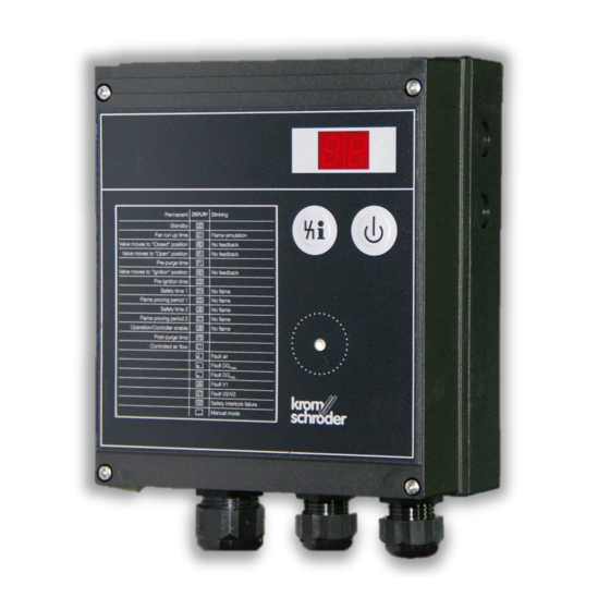
Page 75: Operating Controls And Dimensions
D: Optical interface E: BCU label with the most important status messages in English Additional stickers in D, F, I, NL and E enclosed ø 5 ø 5 BCU 370 · Edition 01.19... -
Page 76: Converting Units
Technical data 9 .3 Converting units See www.adlatus.org BCU 370 · Edition 01.19... -
Page 77: Legend
Ignition transformer Gas valve Flame signal Operating signal Fault signal Reset Input signal Output signal Flame simulation check Pressure switch (DL for air, DG for gas) Ignition/Ignition position Three-point step controller Actuator (in connection diagram) BCU 370 · Edition 01.19... -
Page 78: Glossary
In the event of a fault lock-out of the BCU, the fault signalling contact closes, the display blinks and shows the current program step, see page 37 (Fault mes- sage (blinking)). The gas valves are disconnected from BCU 370 · Edition 01.19... -
Page 79: Annex
Fault Air supply during 2 safety time on start-up d7 Fault Air supply during 2 flame proving period d8 Fault Air supply during operation dP Fault Air supply during pre-purge time ▼ BCU 370 · Edition 01.19... - Page 80 Fault DG during 1 flame proving period o6 Fault DG during 2 safety time during operation o7 Fault DG during 2 flame proving period o8 Fault DG during operation ▼ BCU 370 · Edition 01.19...
- Page 81 52 Permanent remote reset 53 Timing cycle too short 55 DG oscillating 56 Open + Close set simultaneously 99 Internal error H0 Switch-on delay time/pause time C1 Controlled air flow H8 Controller enable signal delay time BCU 370 · Edition 01.19...
-
Page 82: Feedback
Strotheweg 1 · 49504 Lotte (Büren) contact us Germany Tel. +49 541 1214-0 We reserve the right to make technical Fax +49 541 1214-370 modifications in the interests of progress. hts.lotte@honeywell.com Copyright © 2019 Elster GmbH www.kromschroeder.com All rights reserved. BCU 370 · Edition 01.19...