Table of Contents
Advertisement
Quick Links
OPERATING AND MAINTENANCE MANUAL
Product:
Type:
DESIGNED AND MANUFACTURED BY:
T & R Test Equipment Limited
15-16 Woodbridge Meadows, Guildford, Surrey, GU1 1BJ, United Kingdom
Telephone: 01483 207428
Fax.:
01483 511229
High Voltage AC Test Set
KV3-250 mk2
KV4-300 mk2
KV5-100 mk2
KV5-100T mk2
KV5-200 mk2
0
e-mail:
sales@trtest.com
Web:
www.trtest.com
Advertisement
Table of Contents

Related Manuals for T&R KV3-250 mk2

Summary of Contents for T&R KV3-250 mk2
- Page 1 OPERATING AND MAINTENANCE MANUAL Product: High Voltage AC Test Set Type: KV3-250 mk2 KV4-300 mk2 KV5-100 mk2 KV5-100T mk2 KV5-200 mk2 DESIGNED AND MANUFACTURED BY: T & R Test Equipment Limited 15-16 Woodbridge Meadows, Guildford, Surrey, GU1 1BJ, United Kingdom...
- Page 3 GENERAL SAFETY STATEMENT The following safety precautions should be reviewed to avoid injury to the user and damage to the product (and other products connected to it). To avoid potential hazards only use this product as specified. Only suitably qualified personnel should use this equipment. Servicing of this product should only be carried out by suitably qualified service personnel.
- Page 4 HIGH VOLTAGE SAFETY It is essential to follow safe working procedures when working with high voltage. Information on accepted codes of practice should be obtained from your local heath and safety regulatory body. IEEE standard 510-1983 (IEEE Recommended Practices for Safety in High-Voltage and High- Power Testing) provides a working framework for establishing safe procedures, but must be read in conjunction with local regulations and accepted codes of practice.
- Page 5 SAFETY TERMS AND SYMBOLS The following safety symbols appear on the equipment: CAUTION/WARNING – Refer to manual DANGER – High voltage Mains off Mains on The following safety symbols appear in this manual: This action or procedure may be dangerous if not carried CAUTION out correctly, and may cause damage to the equipment or connected equipment.
-
Page 6: Table Of Contents
CONTENTS DESCRIPTION OF EQUIPMENT Electrical Specification 1.1.1 Supply Requirements 1.1.2 Output Specifications 1.1.3 Zero Voltage Interlock 1.1.4 External Interlock Output Voltage Control Overload Protection 1.3.1 Variable overload Metering Fault Burn Facility (except KV5-200 mk2) 1.5.1 Fault Burning 1.5.2 Burn Switch High Voltage Connection Construction Timer Operation (KV5-100T mk2 only) - Page 7 MAINTENANCE STANDARD ACCESSORIES OVERALL PERFORMANCE SPECIFICATION REVISION...
-
Page 8: Description Of Equipment
DESCRIPTION OF EQUIPMENT Electrical Specification 1.1.1 Supply Requirements KV5-100 mk2 115/230V 10% 600VA max KV3-250 mk2 115/230V 10% 900VA max KV4-300 mk2 230V 10% 1400VA max KV5-200 mk2 230V 10% 1100VA max 1.1.2 Output Specifications The output voltage, current and duty cycle are as follows:... -
Page 9: Output Voltage Control
Trip current ranges Unit KV5-100 mk2 2, 4, 6, 8, 10, 12mA 20, 40, 60, 80, 100, 120mA KV3-250 mk2 5, 10, 15, 20, 25, 30mA 50, 100, 150, 200, 250, 300mA KV4-300 mk2 6, 12, 18, 24, 30, 36mA... -
Page 10: Metering
The equipment is provided with the following metering ranges using analogue moving coil meters: Metering Ranges Unit Voltage Current High KV5-100 mk2 10mA 100mA KV3-250 mk2 1.6kV 3.2kV 30mA 300mA KV5-200 mk2 20mA 200mA The ranges on both instruments are selected by means of switches located on the front panel. -
Page 11: Fault Burn Facility (Except Kv5-200 Mk2)
Fault Burn Facility (except KV5-200 mk2) The KV5-100 mk2, KV3-250 mk2 and KV4-300 mk2 are provided with an internal current limit circuit which limits the output current from the unit under short circuit conditions. This can be used to “burn” faults. -
Page 12: Timer Operation (Kv5-100T Mk2 Only)
Timer Operation (KV5-100T mk2 only) The KV5-100T mk2 is fitted with a 5 second-5 min test duration timer. The test timer has two controls; ‘Select Test Time’ and ‘Alarm Cancel’. The timer has nine switch-selectable ranges of 5, 10, 15, 20, and 30 seconds and 1, 2, 3 and 5 minutes. There is an ‘OFF’ position for when the timer operation is not required. -
Page 13: Operation
OPERATION Safety The outputs from all units in the range are very dangerous, and if used incorrectly could be fatal. The unit must only be installed, operated, and maintained by suitably qualified and trained personnel. It is essential to follow accepted safety procedures and local health and safety regulations and guidelines when installing and operating high voltage equipment. -
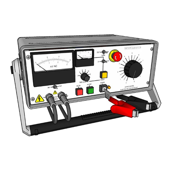
Page 14: Front Panel Layout
Front Panel Layout Figure 2.1 KV5-100 mk2 front panel kV.AC Figure 2.2 KV3-250 front panel... - Page 15 Figure 2.3 KV5-100T front panel Figure 2.4 KV5-200 front panel...
-
Page 16: Front Panel Control Functions
Figure 2.5 KV4-300 mk2 front panel 2.2.1 Front Panel Control Functions kV Meter Displays output voltage mA Meter Displays load current mA x1/x10 selector switch Selects mA meter range Burn switch Selects burn facility Trip reset switch Resets the output current trip HV Output lead HV output to object under test kV meter range switch... -
Page 17: Method Of Operation
Method of Operation 2.3.1 Connections Before making any connections please ensure that you are aware of all hazards relating to the system and environment in which it is operating. Ensure that the key switch is in the off position and the key is removed before making any connections. -
Page 18: Maintenance
MAINTENANCE Maintenance and repair of the KV5-100 mk2 series must only be carried out by suitably qualified and trained personnel. Potentially lethal voltages are present inside the unit and on the output leads. Ensure that the unit is disconnected from the mains before removing WARNING any covers. -
Page 19: Standard Accessories
Mains input lead. 2 keys (for mains ON/OFF switch). Operating & Maintenance Manual. 1x F5A 1¼ inch fuse and 1x T4A 20mm fuse: KV5-100 mk2, KV3-250 mk2. 1xT5A 1¼ inch fuse and 1xT8A 20mm fuse: KV4-300 mk2. 1 off T6.3A: KV5-200 mk2. -
Page 20: Overall Performance Specification
OVERALL PERFORMANCE SPECIFICATION Insulation resistance at 500V DC: >10 megohms between mains input and frame. Applied voltage test: 2.0kV RMS for 1 minute between mains input and frame. Accuracy of instruments kV meter: ±1.5% of FSD mA meter: ±2.5% of FSD Instrument calibration is traceable to national standards. -
Page 21: Revision
REVISION Product / Type: KV5-100 mk2 series High Voltage AC Test Systems File: KV5-100mk2 series manual v5.doc Author: P Cole Issue / Date: 5 / 24.06.2013 Modified By: Checked By: Date: 24.06.13... - Page 22 Circuit diagram A2/001910 KV5-100 mk2 Other unit circuit diagrams available on request A2/000925 KV3-250 A2/001924 KV4-300 mk2 A2/001948 KV5-100T A2/001708 KV5-200...
Need help?
Do you have a question about the KV3-250 mk2 and is the answer not in the manual?
Questions and answers