Advertisement
Advertisement
Table of Contents

Summary of Contents for Foxtronics FOXCART MARK II
- Page 1 FOXCART MARK II OPERATION AND SERVICE MANUAL UNIT WEIGHT - ALL MODELS 1200 / 1600 / 2000 APPROX. 600 POUNDS FOXTRONICS THE POWER CART WITH MUSCLE LOVE FIELD - DALLAS TEXAS MADE IN THE USA 3448 WEST MOCKINGBIRD LANE PHONE (214) 358-4425...
-
Page 2: Table Of Contents
TABLE OF CONTENTS PAGE 1. AN OVERVIEW 2. PURPOSE OF EQUIPMENT 3. MODELS 3.-4. 4. OPTIONS 5. DESCRIPTION 6. PREPARATION FOR USE 7. OPERATION 8. PREVENTIVE MAINTENANCE 9. TROUBLESHOOTING 10.-11. 10. FIGURES / DIAGRAMS 11. APPENDIX A 12. APPENDIX B... -
Page 3: An Overview
AN OVERVIEW This manual provides the operating and maintenance procedures for the Mark II series Foxcart Ground Power Units. The first part of this manual covers operating procedures that are typical for aircraft Ground Power Units operating from an alternating current source. Preparation for use and routine maintenance are also covered. -
Page 4: Purpose Of Equipment
PURPOSE OF EQUIPMENT The Foxcart ground power unit is designed to provide smooth, high current DC power to aircraft during engine starts or ground maintenance. The Foxcart, when used as an external DC source, eliminates or minimizes excessive current drain from the aircraft’s battery and battery relay contacts. It is also designed as a low profile unit that requires minimum ventilation and is easily moved in a crowded hangar by one person. -
Page 5: Models
MODELS All units are provided in functional configuration with standard 15 Ft. DC cables, DC plug and 50 Ft. AC cable with Hubbell 460P7W AC plug. MODEL 1200 This is a single-phase power input unit and should only be considered if three-phase power is not available. - Page 6 MODEL 2000 This is our HI-LINE unit that delivers maximum power output. OUTPUT VOLTS: 28 VDC PEAK DC OUT: 2000 AMPS CONTINUOUS DC OUT: 1000 AMPS INPUT POWER REQUIRED: 208-240 VOLTS PEAK * THREE PHASE 100 AMPS/PER PHASE 380-480 VOLTS PEAK * THREE PHASE 70 AMPS/PER PHASE 100 AMPS SERVICE OTHER VOLTAGES AVAILABLE UPON REQUEST.
-
Page 7: Options
OPTIONS EXTRA LENGTH OF AC CABLE EXTRA LENGTH OF DC CABLE Lengths over 25’ not recommended. SOFTSTART Limits Starting Current to 1100 AMPS to protect engine starters and starter drive that require this feature SHIPPING CRATE WEATHER PROOFING Extra protection from rain and snow REVERSE CURRENT DIODES Prevents aircraft batteries from draining into the Foxcart if power is shut off and the Foxcart is not... -
Page 8: Description
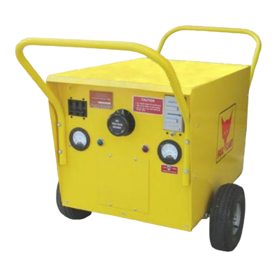
DESCRIPTION The Foxcart is enclosed in an all-steel chassis frame with a three-piece steel box siding. The power cables can be wrapped around the handles or coiled on top for storage. The wheels can be locked in place to prevent movement. Both power cables are clamped internally to the frame for strain relief. Location and identification of the controls are shown in Figure 2. -
Page 9: Preparation For Use
PREPARATION FOR USE The Foxcart is shipped completely assembled except for the handles. Attaching hardware is in- serted into the mounting holes where the handles are to be mounted for your convenience. Verification of Options and Strapping should be checked before use. Incorrect Primary Supply Voltage or Strapping could cause damage or improper DC Output. -
Page 10: Operation
OPERATION Move the Foxcart into position and set the wheel brakes. Ensure that 14/28-volt selector switch is in the same voltage range as the Aircraft. (If cart is so equipped with this optional feature). Plug the Foxcart Input Power Cable into the AC Outlet. Switch the Foxcart ON/OFF breaker to “ON”... -
Page 11: Preventive Maintenance
PREVENTIVE MAINTENANCE Routine maintenance should be performed periodically. Since the wheels and fan motor are the only moving parts on the Foxcart, maintenance is kept to a minimum. Oil fan motor and all other moveable parts. Using compressed air and a dry cloth, clean accumulated dust and grime from unit. Perform visual inspection and tighten any loose nuts and bolts. -
Page 12: Troubleshooting
If the Foxcart has been operational for a period of time and has failed, use the following steps to assist in isolating the problem. If the problem cannot be isolated, please call Foxtronics for assistance. The phone number is (214) 358-4425. Replacement parts may be ordered from the same number. - Page 13 Inspect the interior of the Foxcart for any signs of arcing or burning, such as wires or connections. Remove rectifier bus bars and any attaching wiring. Using a DMM Diode Tester, test all the diodes. All readings should be similar in the forward direction and infinite in the reverse direction. Remove buss bars and attaching wires from reverse current diodes.
-
Page 14: Figures / Diagrams
FIGURES / DIAGRAMS FIGURE 1 FOXCART DIMENTIONS FIGURE 2 FRONT PANEL COMPONENTS FIGURE 3 STRAPPING CHART FIGURE 4 MAJOR COMPONENTS FIGURE 5 MODEL 1200B w/REVERSE CURRENT FIGURE 6 MODEL 1600B/2000B w/REVERSE CURRENT & SOTFSTART FIGURE 7 MODEL 1600B/2000B w/14/28VDC OPTION FIGURE 8 MODEL 1600B/2000B w/STEPDOWN TRANSFORMER... - Page 15 FOXCART MARK II DIMENSIONS 50.5 DIMENSIONS ACROSS HANDLES HANDLE HEIGHT ABOVE GROUND BOX HEIGHT 31.0 BOX DIMENSION 21.0 BOX DIMENSION 30.0 GROUND LEVEL OUTSIDE WHEELS DIMENSION UNIT WEIGHT − ALL MODELS 1200/1600/2000 APPROX. 600 POUNDS FIGURE 1.
- Page 16 UTILITY 115 VOLT STRAPPING COVER PLATE 15 AMP FUSE INPUT POWER STRAPPING INPUT POWER STRAPPING PANEL ITEM DESCRIPTION 3448 W. Mockingbird Ln. foxtronics Dallas, TX 75235 PHONE: 214/358-4425 incorporated FAX: 214/358-1519 TITLE: FOXCART FRONT PANEL COMPONENTS DRAWING NO: 400- DATE:...
- Page 17 NOTE: IF INPUT AC POWER IS 380 VAC OR ABOVE AND STEPDOWN TRANSFORMER IS INSTALLED. TERMINALS W, W, Y AND Z ARE DISCONNECTED. 440V 480V FOXCART MODEL 1600-C ONLY 3448 W. Mockingbird Ln. foxtronics Dallas, TX 75235 PHONE: 214/358-4425 incorporated FAX: 214/358-1519 TITLE: FOXCART AC INPUT VOLTAGE STRAPPING...
- Page 25 ASSEMBLY: MODEL 1200 / 60 Hz APPENDIX A-1 COMPONENTS DESCRIPTION UNITS REQ. ASSEMBLY COMPONENTS DESCRIPTION UNITS REQ. ASSEMBLY 401-0001-012 412-7-T2 TAP SWITCH 401-0002-016 3M578 FAN MOTOR 401-0003-016 2C842-8 / 12” BLADE 401-0004-016 TRIPLET / DC VOLT METER 0-40VDC 401-0005-016 DC AMP METER: DUAL 0-800; 0-1600 401-0006-001 RED-DOTCVR CCD DCI-78440135000 401-0006-006...
- Page 26 ASSEMBLY: MODEL 1600 / 60 Hz APPENDIX A-2 COMPONENTS DESCRIPTION UNITS REQ. ASSEMBLY COMPONENTS DESCRIPTION UNITS REQ. ASSEMBLY 401-0001-016 412-7-T2 TAP SWITCH 401-0002-016 3M578 FAN MOTOR 401-0003-016 2C842-8 / 12” BLADE 401-0004-016 TRIPLET / DC VOLT METER 0-40VDC 401-0005-016 DC AMP METER: DUAL 0-800; 0-1600 401-0006-001 RED-DOTCVR CCD DCI-78440135000 401-0006-006...
- Page 27 ASSEMBLY: MODEL 2000 / 60 Hz APPENDIX A-3 COMPONENTS DESCRIPTION UNITS REQ. ASSEMBLY COMPONENTS DESCRIPTION UNITS REQ. ASSEMBLY 401-0001-016 412-7-T2 TAP SWITCH 401-0003-016 2C842-8 / 12” BLADE 401-0002-016 3M458 FAN MOTOR 50Hz 401-0004-016 TRIPLET / DC VOLT METER 0-40VDC 401-0005-020 DC AMP METER: DUAL 0-1000;...
- Page 28 ASSEMBLY: 50 Hz OPTION (Prior to 3-1-07) APPENDIX A-4 COMPONENTS DESCRIPTION UNITS REQ. ASSEMBLY COMPONENTS DESCRIPTION UNITS REQ. ASSEMBLY 401-0003-018 3M459 FAN MOTOR 50Hz 401-0003-019 3M492 MOUNT 401-0003-020 SPLIT RING ADAPTOR ASSEMBLY: 50 Hz OPTION (After 3-1-07) COMPONENTS DESCRIPTION UNITS REQ. ASSEMBLY COMPONENTS DESCRIPTION...
- Page 29 APPENDIX B Chart for 1200 Chart for 1600 Chart for 2000...
Need help?
Do you have a question about the FOXCART MARK II and is the answer not in the manual?
Questions and answers