Table of Contents
Advertisement
Quick Links
- 1 Before You Start Programming
- 2 The Principle of Programming
- 3 How to Programme Individual Functions (Inputs 1 to 8)
- 4 Alarm on Open or Closed Signal Contact (N/C, N/O)
- 5 Selection of Output Relay (Output(S) a And/Or Output B)
- 6 Inhibit of Incoming Alarm (Inhibit)
- 7 Alarm on Cable Failure (Cable Failure)
- Download this manual
Programming manual
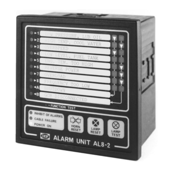
Alarm panel AL8-2
4189320003D
•
Compact Q96 design
•
Extremely easy push-button programming (no jumpers
or the like)
•
Individual programming of each input:
N/O or N/C, time delay, alarm inhibit, output
and cable supervision
•
Up to 5 units in master/slave configuration
•
Clear identification of first alarm received in case of
successive alarms
DEIF A/S
Frisenborgvej 33, DK-7800 Skive Fax: (+45) 9614 9615
Denmark
Tel: (+45) 9614 9614
E-mail: deif@deif.com
Advertisement
Table of Contents

Summary of Contents for Deif AL8-2
- Page 1 Programming manual Alarm panel AL8-2 4189320003D • Compact Q96 design • Extremely easy push-button programming (no jumpers or the like) • Individual programming of each input: N/O or N/C, time delay, alarm inhibit, output and cable supervision • Up to 5 units in master/slave configuration •...
-
Page 2: Table Of Contents
AL8-2 – Programming manual CONTENTS: BEFORE YOU START PROGRAMMING ..............3 THE PRINCIPLE OF PROGRAMMING ................ 6 WHICH FUNCTIONS MAY BE PROGRAMMED? ............7 HOW TO PROGRAMME INDIVIDUAL FUNCTIONS (INPUTS 1 TO 8)....... 8 ALARM ON OPEN OR CLOSED SIGNAL CONTACT (N/C, N/O) ......9 SELECTION OF OUTPUT RELAY (OUTPUT(S) A AND/OR OUTPUT B) .... -
Page 3: Before You Start Programming
AL8-2 – Programming manual On delivery, the AL8-2 alarm panel is programmed to the following functions: Individual functions • Alarm on closed signal contact (N/O) • No activation of output relays A and B on an alarm condition • Inhibit function NOT activated •... - Page 4 AL8-2 – Programming manual Secondly, the bezel and front sheet are removed to give access to the programming front plate. The descriptive text for alarm channels 1-8 and the output channels A and B is written/set on the shown text label.
- Page 5 AL8-2 – Programming manual ABC123 ABC123 ABC123 ABC123 WRONG CORRECT The horizontal line at the top of the label indicates the left margin. The text label is mounted behind the front sheet which has an adhesive rear. Label and front sheet are easily separated and put together again, though.
-
Page 6: The Principle Of Programming
AL8-2 – Programming manual THE PRINCIPLE OF PROGRAMMING Programming of the alarm panel is carried out by means of the 3 push-buttons CHANNEL SELECT, FUNCTION SELECT and ENTER, positioned at the lower right corner of the front plate. The principle of programming is as follows: "Point"... -
Page 7: Which Functions May Be Programmed
AL8-2 – Programming manual WHICH FUNCTIONS MAY BE PROGRAMMED? It is possible to program 5 functions for each of the input channels 1 to 8. Furthermore, programming of 4 common functions is possible. The individual functions are as follows: 1) Registration of alarm on open or closed signal contact - i.e. -
Page 8: How To Programme Individual Functions (Inputs 1 To 8)
AL8-2 – Programming manual HOW TO PROGRAMME INDIVIDUAL FUNCTIONS (INPUTS 1 TO 8) Set AL8-2 to programming status: Press the PRG button. This button is slightly countersunk when compared with the front plate, and a thin, sharp tool like e.g. a small screwdriver, a needle or the like must be applied to press this button. -
Page 9: Alarm On Open Or Closed Signal Contact (N/C, N/O)
AL8-2 – Programming manual ALARM ON OPEN OR CLOSED SIGNAL CONTACT (N/C, N/O) The "N/O" and "N/C" LEDs indicate the actual function as follows: NOTE: Both LEDs are lit simultaneously. EITHER: GREEN FUNCTION: Alarm on closed signal contact FUNCTION: Alarm on open signal contact... -
Page 10: Selection Of Output Relay (Output(S) A And/Or Output B)
AL8-2 – Programming manual SELECTION OF OUTPUT RELAY (OUTPUT(S) A AND/OR OUTPUT B) The LEDs for "OUTPUT A", "OUTPUT B" indicate the actual function as follows: NOTE: Both LEDs are lit simultaneously. EITHER: RED OUTPUT A FUNCTION: OUTPUT B output... -
Page 11: Alarm On Cable Failure (Cable Failure)
AL8-2 – Programming manual ALARM ON CABLE FAILURE (CABLE FAILURE) The LED for "CABLE FAILURE" indicates the actual function as follows: EITHER: CABLE FAILURE FUNCTION: No alarm on cable breakage CABLE FAILURE FUNCTION: GREEN Alarm on cable breakage Pressing FUNCTION SELECT causes the indication/function to change from one to the other. -
Page 12: Selection Of Requested Time Delay (Set Time)
AL8-2 – Programming manual If changing of the just entered function is not requested, press CHANNEL SELECT to step through the channels to find the next to be programmed. You may also terminate the programming by pressing PRG, resulting in the alarm panel returning to normal function. -
Page 13: Selection Of Basic Time
AL8-2 – Programming manual SELECTION OF BASIC TIME: The actual time delay is indicated by the LEDs 1-10 as follows: After entering the function "delayed registration of an alarm con- dition" by pressing ENTER, all LEDs 1-10 are lit. Green light in an LED indicates that an actual (basic) time delay has been selected corresponding to the secs indicated by the number to the left of the relevant LED. -
Page 14: Selection Of Additional Time
AL8-2 – Programming manual SELECTION OF ADDITIONAL TIME: When the basic time has been entered by pressing ENTER, the LEDs marked "+10" and "+20" are lit. The LEDs for basic time will remain lit. The LEDs "+10" and "+20" indicate the actual time delay as... -
Page 15: Programming Of Common Functions
AL8-2 – Programming manual PROGRAMMING OF COMMON FUNCTIONS If the alarm panel has been set to programming status (LED for "PRG": green), press FUNCTION TEST to set the unit to programming status for common functions. The LED for "PRG" remains lit (green) to indicate that the unit has been set to programming status. -
Page 16: Selection Of Time Limited Activation/Deactivation Of Output Relaya
AL8-2 – Programming manual SELECTION OF TIME LIMITED ACTIVATION/DEACTIVATION OF OUTPUT RELAY When the requested function as regards activation/deactivation of output relay A has been entered, the LED for "SET TIME" is lit (green) and the LEDs 1-10 are lit (red/green –... -
Page 17: Selection Of Activation/Deactivation Of Output Relay B On An Alarm Condition (N/O, N/C)
AL8-2 – Programming manual SELECTION OF ACTIVATION/DEACTIVATION OF OUTPUT RELAY B ON AN ALARM CONDITION (N/O, N/C) When output relay A has been programmed, the "OUTPUT B" LED is lit (green) and the "N/O" and "N/C" LEDs indicate the actual function as follows: NOTE: Both LEDs are lit simultaneously. -
Page 18: Delayed Cancellation Of Inhibit Function (0
AL8-2 – Programming manual DELAYED CANCELLATION OF INHIBIT FUNCTION (0..40 secs) When the "INHIBIT" LED is lit (green), the LEDs 1-10 indicate the actual basic time for delayed cancellation of the inhibit function. If all LEDs 1-10 are red, the actual time delay is 0 sec. -
Page 19: Master"/"Slave" Configuration
AL8-2 – Programming manual The programming of common functions is hereby finished, and the alarm panel automatically returns to programming status for individual functions, i.e. the LED for the input channel to which it last was pointed is lit (green) and of course the LED for "PRG"...
Need help?
Do you have a question about the AL8-2 and is the answer not in the manual?
Questions and answers