Table of Contents
Advertisement
Quick Links
www.miniRadioSolutions.com
miniVNA antenna analyzer V224
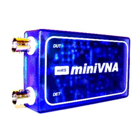
Reference manual for mRS antenna analyser type miniVNA 0.1-180 MHz
The device is designed to measure antenna impedance and filters over the HF and VHF frequency range.
The small hardware (9x5.5x3cm) uses an USB connection to a PC where the antenna parameters can be
displayed, one full scan takes about 0.5 sec per 500 samples, the instrument will give a big help to tune and
design antennas especially for radio amateurs.
The original software runs under Windows PC, by the way many hams worked on different version such as
DOS, LINUX and PDA with Windows CE (Windows Mobile 2002-2003).
Several Hams have actively contributed to the development and supported the project in different ways, I
would like to thanks in particular Juan Carlos(nominativo), Stewart G3RXQ, Peter PA0PDW and all other
hams very active in the discussion group at
System requirements
•
PC with cpu 500Mhz or better, WIN98, WIN2000, XP or LINUX are supported
•
The device work also with pocket PC, WIN CE are supported.
Before you start
•
Do not expose this device at strong rf fields (expecially with antenna connected), may be cause
permanent damage of internal detector.
•
In case of battery supply (not USB use) do not excede 5VDC.
•
In antenna analisys this device generate about 1mW from 1 to 180 Mhz: it may cause interference
and local QRM to others HAM radio station.
http://groups.yahoo.com/group/analyzer_iw3hev
1
Advertisement
Table of Contents

Summary of Contents for Mini Radio Solutions miniVNA
- Page 1 V224 Reference manual for mRS antenna analyser type miniVNA 0.1-180 MHz The device is designed to measure antenna impedance and filters over the HF and VHF frequency range. The small hardware (9x5.5x3cm) uses an USB connection to a PC where the antenna parameters can be displayed, one full scan takes about 0.5 sec per 500 samples, the instrument will give a big help to tune and...
- Page 2 V224 Analyser Characteristics: * Frequency coverage 0.1Mhz to 180MHz * DDS Generator with 0 dBm output * 2 Ports allow Transmission Measurements e.g. filters, traps * USB1.1 and USB2 compatibility * RS232 optional socket for Pocket PC`s or Remote Displays * Fast Scan (typical 0.6 sec for 500 points)
- Page 3 Inside view 1. SW1 SWITCH MODE: select mode between USB and RS232. 2. J4 RS232 STRIP: to connect the miniVNA to RS232 port (see Application Notes). 3. JP2 PRG CONNECTION: to program cpu in-circuit. 4. S2 RESET BUTTON: to reset the miniVNA.
- Page 4 V224 The analyzer has USB 1.0/2.0 connection to the PC via standard USB cable. The necessary 5 Vdc power will be taken from the PC without the need of an external power supplier. An optional RS232 port is available in case of PDA connection, see the fig. for connection pads (to use RS232 the user has to add 3 wires plus DB9 cannon).
- Page 5 V224 1. The reflection mode To enable reflection mode click on the icon “Antenna” This mode is used for antenna measurement. In this mode you can read most of the information like return loss, X, R, Z, reflection coefficient and phase , see below an example of 20 meters loop antenna response.
- Page 6 V224 How to measure cable length. To enable cable measurement click on the icon “Cable Length” Set Marker1 by left click of the mouse on the graph Set Marker2 by right click of the mouse on the graph To measure cable length place both markers on two consecutive Z peaks as per the picture below.
- Page 7 V224 How the analyser works The hardware is based on a DDS (AD9951-14 bits) which acts as a sweep generator feeding a directional coupler; the two coupled outputs are compared in phase and amplitude. In reflection mode the Return Loss...
- Page 8 V224 Applicatio Notes Analyser with wireless connection In case you need to place the analyzer under the antenna you can receive the data via a wireless adapter. You will have to power both analyzer and adapter with external 3.6-5.0 VDC source and use the RS232 interface connection.
Need help?
Do you have a question about the miniVNA and is the answer not in the manual?
Questions and answers
need windows 10 software update for miniVNA V230